Tank-Mounting Bulldozer M9.
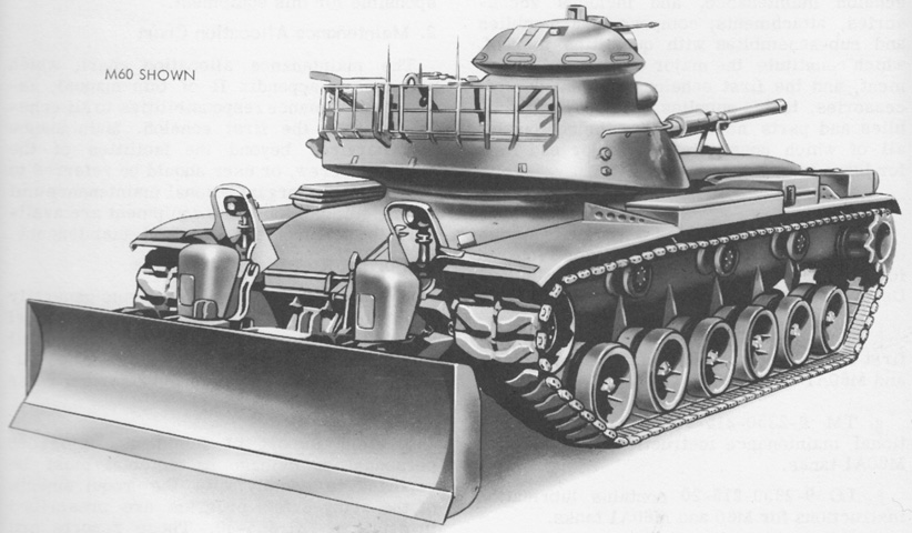
The M60 and M60A1 tanks necessitated changes to the tank mounting bulldozer M8A1 used on the M48A2, resulting in the tank-mounting bulldozer M9. Total weight for the M9 was 8,887.74lb (4,031.48kg) without oil, with the oil pump mount assembly weighing 121.53lb (55.126kg); the headlamp adapters 8.00lb (3.63kg); headlamp guards and supports 8.20lb (3.72kg); front mounting brackets and moldboard 5,994.76lb (2,719.22kg); hydraulic cylinders, piping, reservoir, and guards 2,583.62lb (1,171.93kg); the control assembly 160.26lb (72.694kg); and the mounting fixture and templates 11.37lb (5.157kg). The tank could move at 3mph (5kph) while bulldozing in low gear with the engine at 1,500rpm, and it was recommended not to exceed 15mph (24kph) with the bulldozer installed. (Picture from TM 9-2590-209-14.)
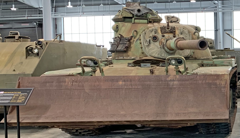
The moldboard is in the carrying position on this tank, and the extended headlights peering over the moldboard edge are obvious.
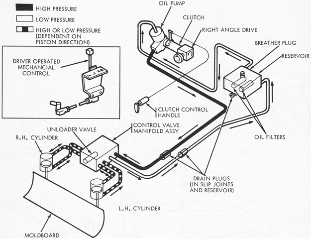
A schematic of the hydraulic system is drawn here. (Picture from TM 9-2590-209-14.)
The hydraulic oil reservoir was mounted on the left rear fender, and heavy wall steel tubing was routed under the hull to the hydraulic manifold on the hull front. (Picture from TM 9-2590-209-14.)
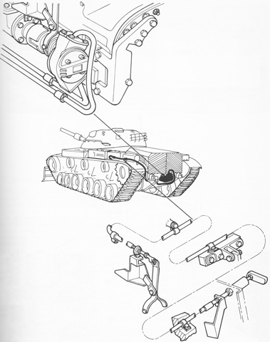
An oil pump, seen at the top left, was attached to the power take-off shaft at the rear of the transmission. It was engaged using a clutch, with a clutch control assembly (drawn at the lower right) operated by a handle. (Picture from TM 9-2590-209-14.)
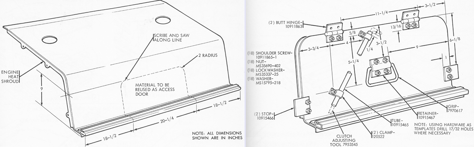
The engine heat shroud was modified to create an access door for the hydraulic oil pump mount assembly. (Picture from TM 9-2590-209-14.)
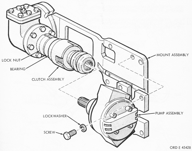
The oil pump is drawn in the process of being installed. The mount assembly consisted of an integral right-angle drive, the clutch, and the pump. The pump rating was 65gpm at 2,800rpm at 1,000psi (250L/min at 2,800rpm at 70kg/cm²), and its safety unloader relief valve was set at 5,000psi (350kg/cm²). (Picture from TM 9-2590-209-14.)
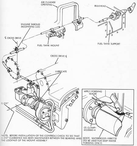
The control linkage for the clutch was routed around the engine compartment and through the engine bulkhead. (Picture from TM 9-2590-209-14.)
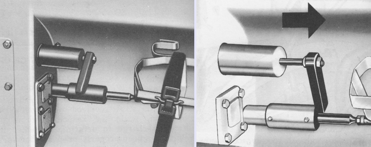
The clutch handle is shown in the engage position on the left and pulled out to the disengage position on the right. The clutch was to be engaged with the tank engine idling. (Picture from TM 9-2590-209-14.)
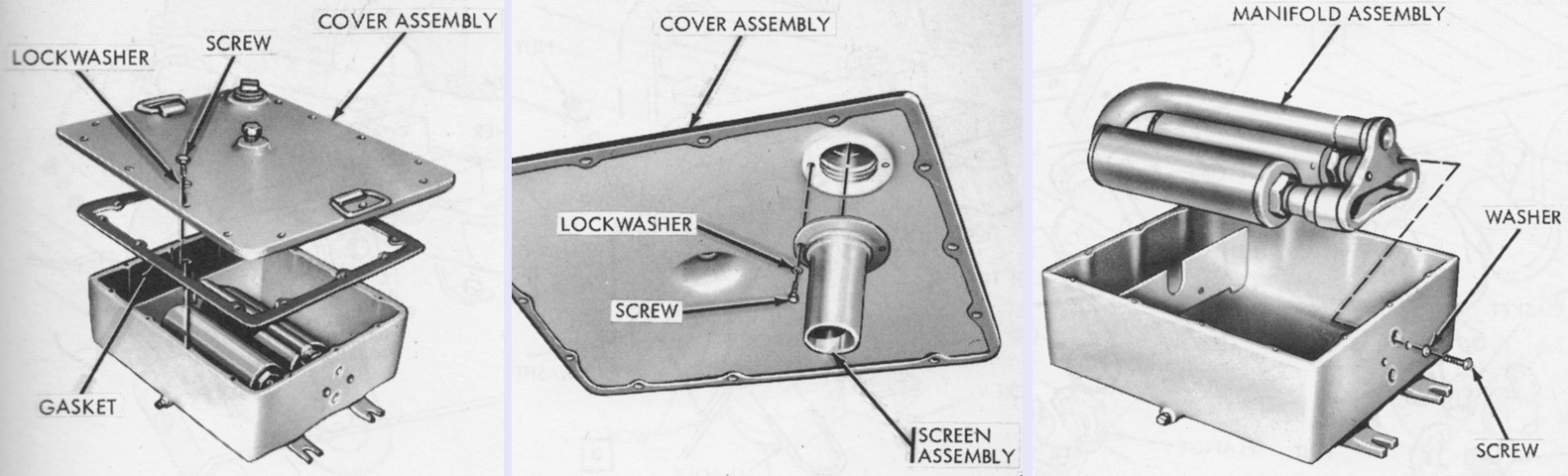
The hydraulic system had a capacity of 25gal (95L) of internal combustion engine OE lubricating oil. An 11.5gal (43.5L) reservoir was mounted on the left rear fender. (Picture from TM 9-2590-209-14.)
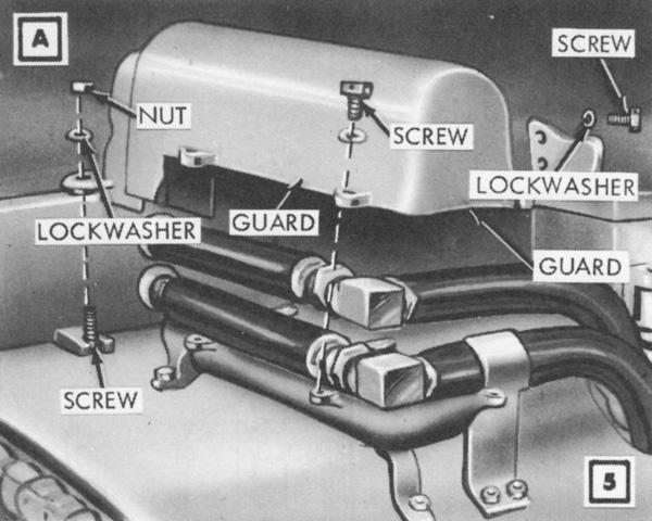
The hydraulic lines connected to the reservoir were protected by a metal guard. (Picture from TM 9-2590-209-14.)
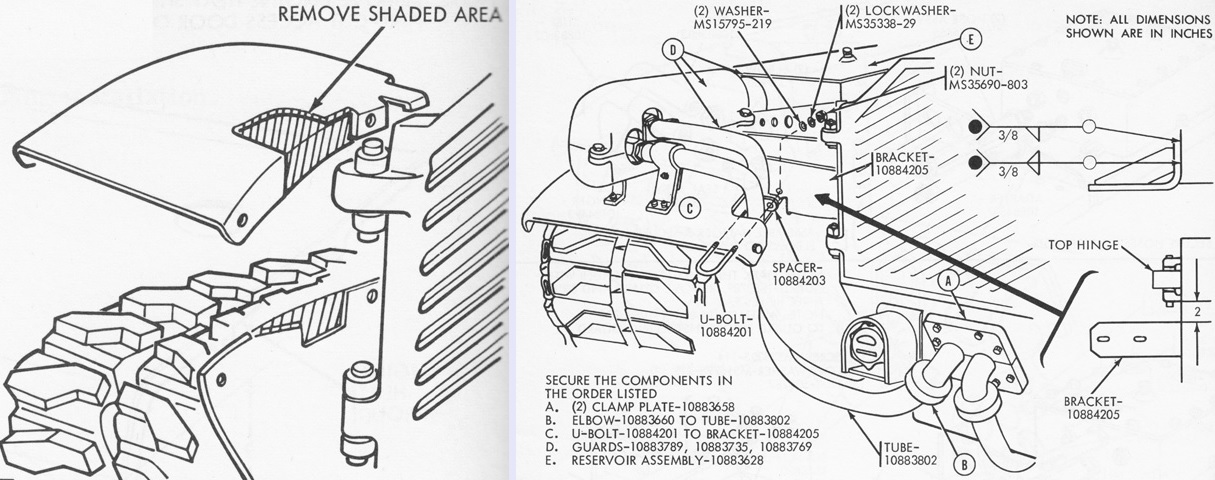
The rear fender needed to be modified as shown on the left to allow clearance for the hydraulic line snaking to the oil pump and the return line from the front manifold. As seen on the right, the tubing to and from the oil pump used the opening for the left brake access plate in the hull rear. The cover plate was removed and stowed, and a new clamping plate was installed to secure the two tubing elbows. (Picture from TM 9-2590-209-14.)
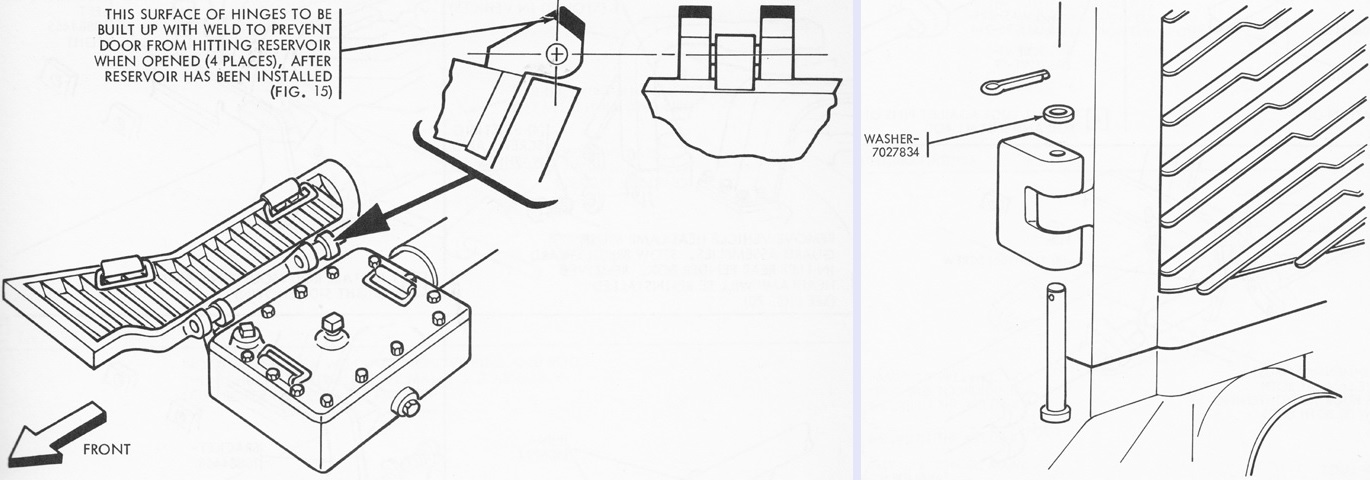
The hinges for the left top engine grille door were built up with weld so that the door did not open fully and damage the reservoir. Similarly, the orientation of the lower left hinge pin on the left engine access door was reversed. (Picture from TM 9-2590-209-14.)
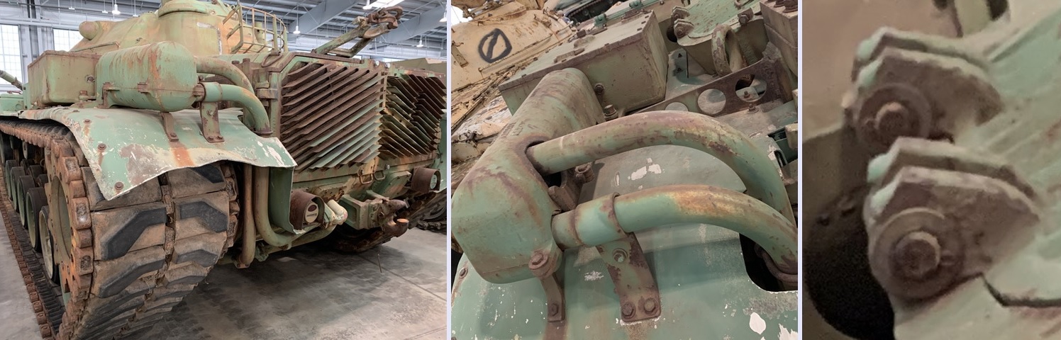
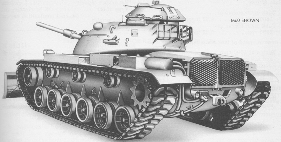
The oil reservoir and guard for the hydraulic lines can be seen installed on this vehicle, along with the cut out in the left rear fender that allowed clearance. In the closeup on the right, the weld bead added to the hinges of the top engine grille door is visible.
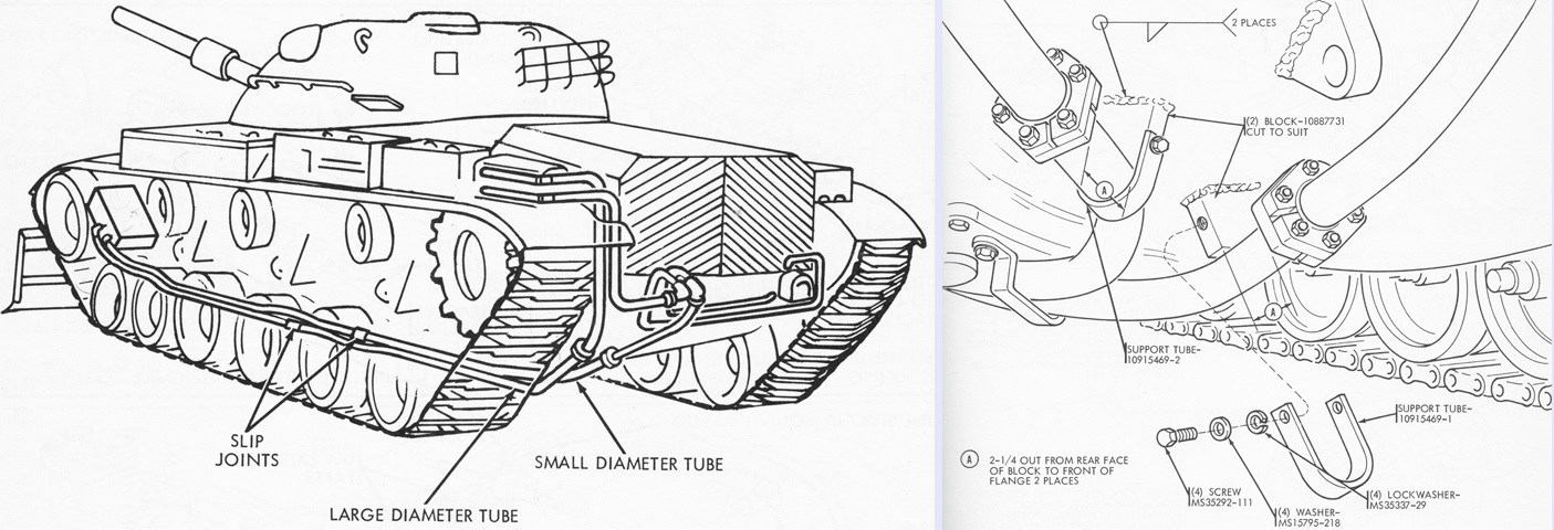
The tubing under the hull rested on blocks welded to the underside of the vehicle. Guards protected the front portions of the hydraulic lines. (Picture from TM 9-2590-209-14.)
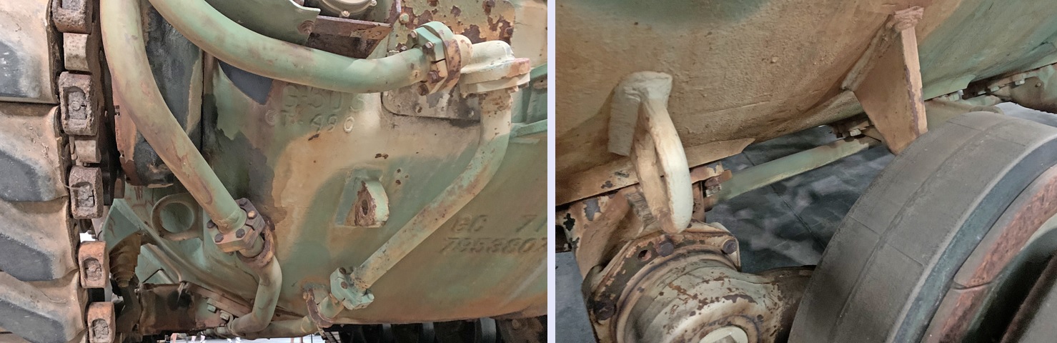
The steel piping is seen headed under the rear of the tank hull in the left image. The new clamping plate and elbows that replaced the left brake access plate are also visible. On the right, the plumbing continues to the front along the hull bottom.
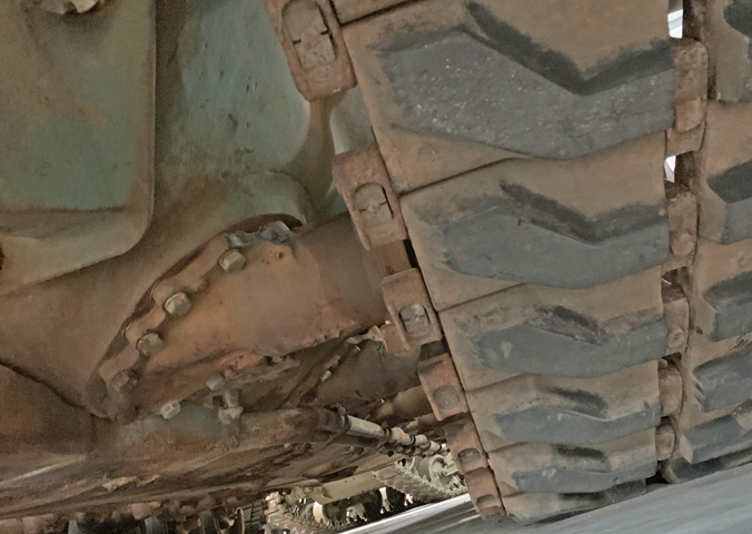
Guards protecting the forward portion of the underhull hydraulic lines can be seen inboard of the suspension station.
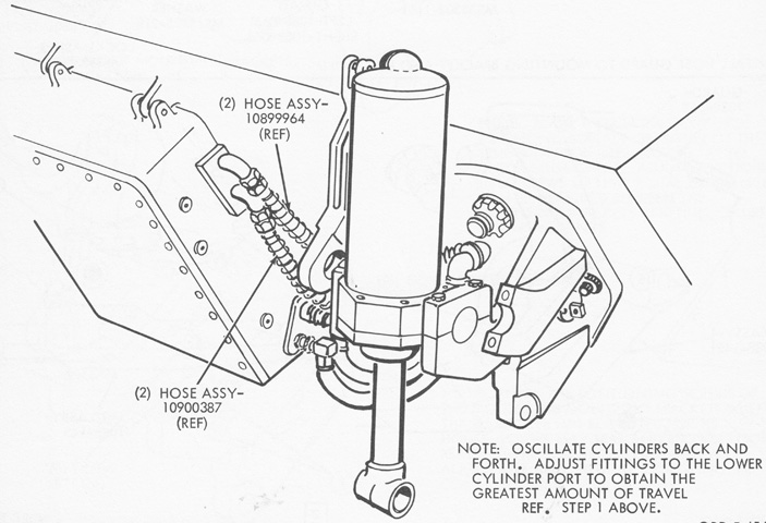
The moldboard was manipulated by two double-acting hydraulic cylinders installed on the hull front, and the left cylinder is drawn here before its metal guard has been installed. The control valve manifold assembly is seen at the left, installed on the lower hull front. Lugs for mounting the manifold assembly were welded to the hull after being located by a special fixture, and pads for the bottom of the manifold assembly were welded to the hull after firmly holding the manifold against the hull in order to determine their position. The cylinder mounting brackets were emplaced over the hull towing lugs. Maximum rate of lift with the tank engine at 1,500rpm was 4.62"/s (11.7cm/s); this was increased to 6.52"/s (16.6cm/s) with the engine running at 2,850rpm. (Picture from TM 9-2590-209-14.)
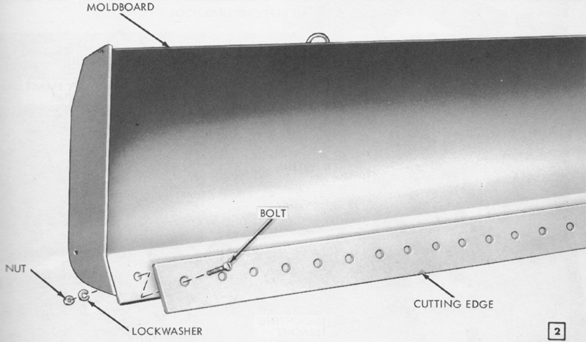
The moldboard featured a reversible cutting edge secured by bolts, nuts, and lockwashers. The moldboard was 146" (371cm) long and 36" (91cm) high, and the cutting edge was 146"x8"x¾" (146cm x 20cm x 1.9cm). The cutting edge was 10" (25cm) below ground at the moldboard's lowest position, 30" (76cm) above ground at its highest, and 29" (74cm) above ground in the carrying position. The cutting edge was 66° with the horizontal when at its lowest position, 58° with horizontal at ground level, and 60° with horizontal in the float position. (Picture from TM 9-2590-209-14.)
The bottom corners of the moldboard were connected to two pushbeams, and the rams from the hydraulic cylinders were inserted into the pushbeams and secured by pins. (Picture from TM 9-2590-209-14.)
The cylinder mounting brackets on the lower hull front and moldboard pushbeams bottom corners are seen in this view. Visible behind the near pushbeam is the guard protecting the hydraulic lines connecting to the control valve manifold assembly. On the right, a view looking farther beneath the front hull shows the hydraulic lines making their way up to the control valve assembly.
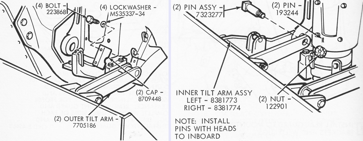
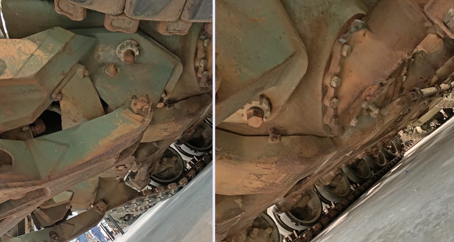
The top corners of the moldboard were connected to the tank by inner and outer tilt arms. (Picture from TM 9-2590-209-14.)
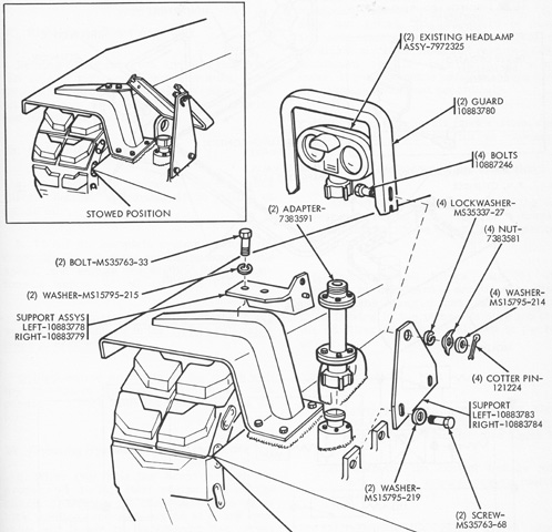
Increased height was needed for the headlights to clear the moldboard. The original headlight brush guards were removed and stowed, and new brush guard supports and brushguards were installed instead, while the headlights were secured to a tall adapter. When the bulldozer was used for removing trees, the headlights were to be stowed and the brush guards folded back into their stowed position as drawn at the upper left. (Picture from TM 9-2590-209-14.)
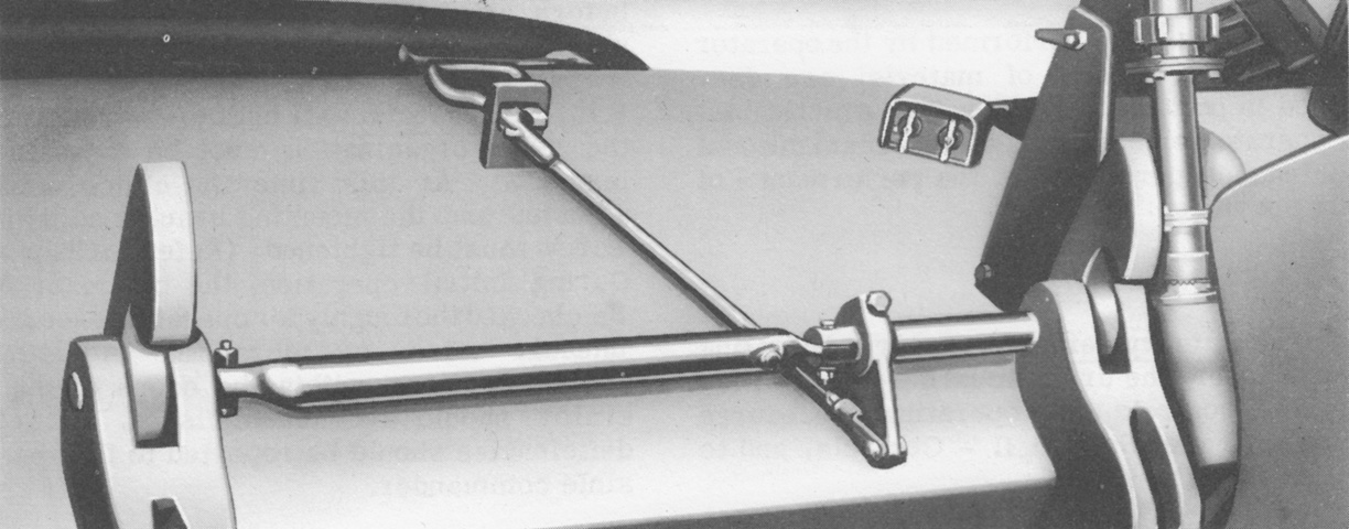
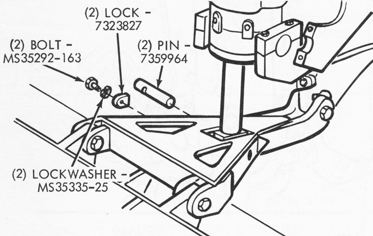
The moldboard was secured when not in use by carrying hooks that rotated on a shaft between the hydraulic cylinder mounting brackets. A handle was provided on the hull front so that the driver could engage or disengage the hooks from his position; a support for the handle was welded to the upper hull front approximately 30¼" (76.84cm) from the centerline of the carrying hook shaft. (Picture from TM 9-2590-209-14.)
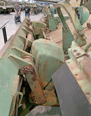
The left outer tilt arm assembly is closest to the camera in this angle, and the guards protecting the hydraulic cylinders are installed. The extended headlight guards are obvious, and the thin carrying hook handle can be seen on the upper hull front reaching down to the carrying hook shaft between the hydraulic cylinders.
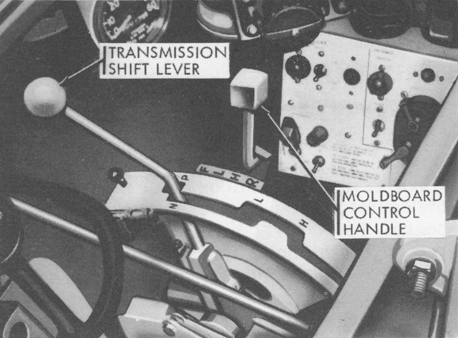
The driver controlled the moldboard with a handle installed next to his transmission control lever. From front to rear, F was for float, where the moldboard would ride on the ground with only its weight providing downward pressure; L was for lowering the moldboard; H was for hold, which used hydraulic pressure to retain the moldboard at a specific position; and R was for raising the moldboard. (Picture from TM 9-2590-209-14.)
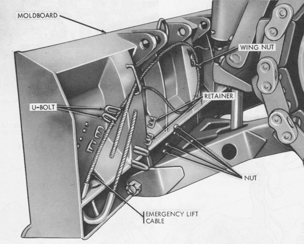
If the hydraulic system failed, the moldboard could still be lifted and secured in its carrying hooks by using emergency lifting cables stowed on the rear of the moldboard (shown here before the tilt arms have been installed). (Picture from TM 9-2590-209-14.)
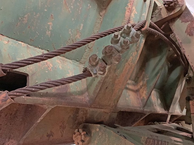
The tilt arms are present on this machine, and the emergency lifting cables, left outer tilt arm assembly, and left pushbeam can all be seen.
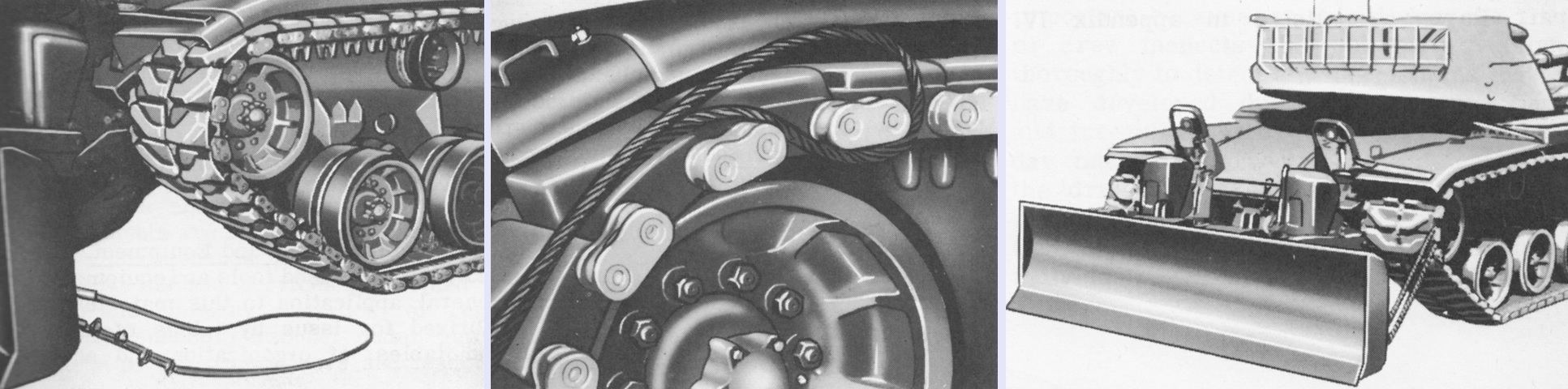
The emergency lifting cables were looped around an end connector and the tank was slowly driven backwards until the moldboard was high enough to be engaged by the carrying hooks. (Picture from TM 9-2590-209-14.)
