Tank Mounting Bulldozer M8A1.
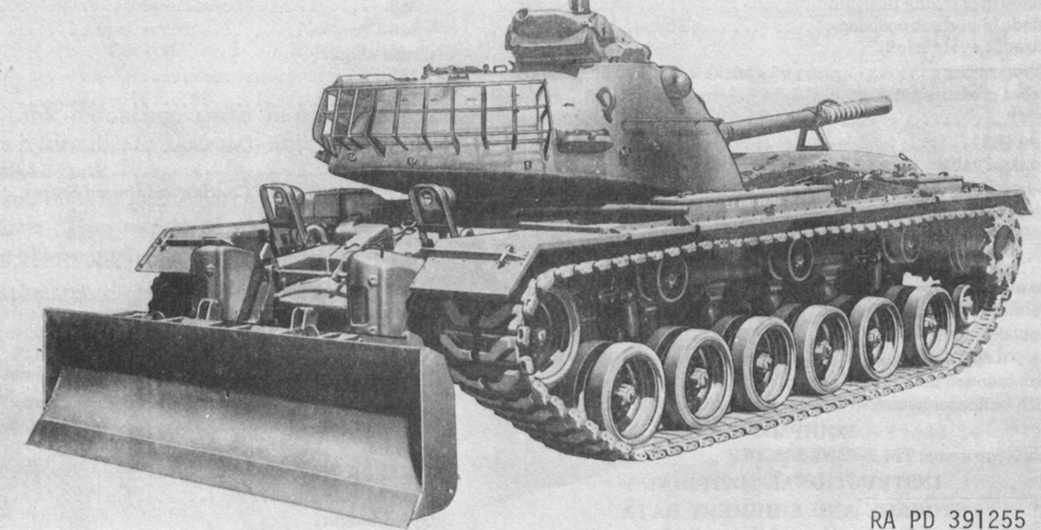
When the 90mm gun tank M48 entered service, work began on a bulldozer mount for it. Originally designated T18E1 and intended to share parts with both the tank-mounting bulldozer M3 and the tank mounting bulldozer T18 under development for the 120mm gun tank M103, when the T18E1 was engineered to be mounted without cutting holes into the hull through which to pass hydraulic lines, the T18 was instead modified to become similar to the T18E1. The T18E1 was standardized as the M8 on 10 January 1957 and could be mounted to the M48, M48C, and M48A1 tanks. The control valves and hydraulic reservoir were mounted on the hull wall at the tank's rear, and pressure was developed by a pump driven by the main engine. When the M48A2 debuted with its revised engine exhaust, the hydraulic reservoir and control valves were moved to the right fender. This new arrangement was standardized as the tank mounting bulldozer M8A1, and is illustrated in the above image.
The M8 weighed 8,778lb (3,982kg), with the M8A1 coming in at 8,400lb (3,810kg). Both used a 146" (371cm) long moldboard, but the M8's moldboard was 36¾" (93.35cm) tall versus the M8A1's 36" (91cm) moldboard. The reversible cutting edge for both was 146"x8"x¾" (371cm x 20cm x 1.9cm). At ground level, the cutting edge formed a 58° angle with horizontal; this was 59° at the float position and 65° at the lowest position. The M8 carried the moldboard at 31" (79cm) above the ground, while the M8A1 carried its moldboard at 27" (69cm) above the ground. The lowest and highest positions were 10" (25cm) below ground and 30" (76cm) above ground for both. The tank's angle of approach was 20° with the blade in both the carrying and highest positions. Both moldboards could be lifted at 5.5"/sec (14cm/sec) at 1,500 main engine rpm, or 10.5"/sec (26.7cm/sec) at 2,800rpm. The recommended maximum forward speed with the bulldozer mounted was 15mph (24kph), and a speed of 1-3mph (2-5kph) could be achieved while bulldozing. (Picture from TM 43-0001-31 Equipment Data Sheets for TARCOM Equipment.)
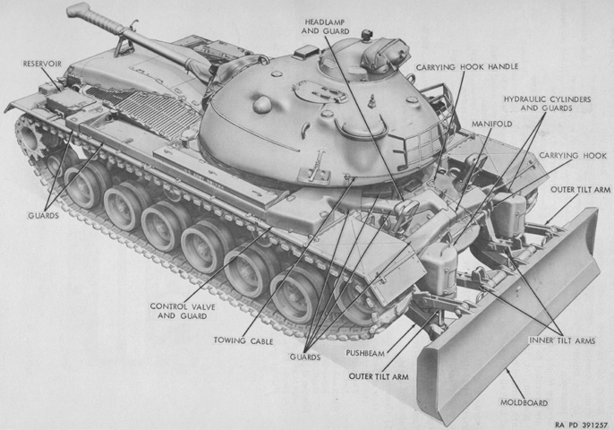
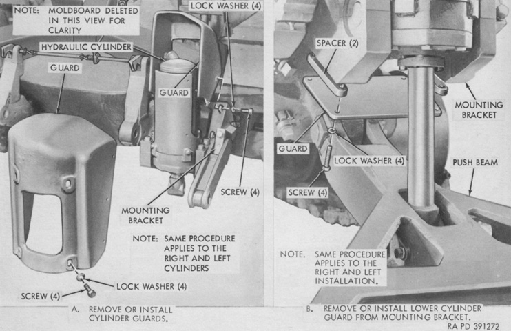
The M8A1 is shown from above with various components labeled. Armor guards protected the hydraulic cylinders, lines, hoses, and manifolds as well as control linkages. (Picture from TM 9-2590-206-15.)
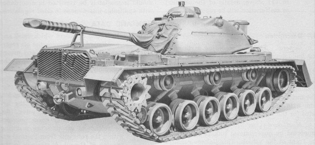
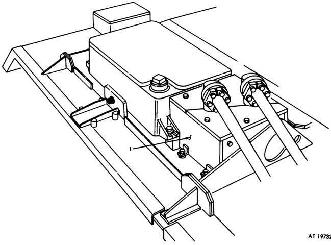
The hydraulic reservoir can be seen on the rear fender from this angle. Shielded hydraulic lines run the length of the fender from the reservoir at the rear to the valve on the front fender. (Picture from TM 9-2590-206-15.)
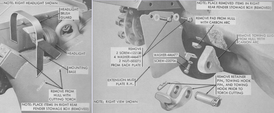
Even though no holes were cut in the hull for hydraulic lines, modifications to the tank were needed to mount the bulldozer kit. For example, the right rear fender stowage box was removed; the headlight brush guards were cut off; the track block normally stowed on the right rear fender was transferred to the left, with new footman loops being welded to the left fender to secure the track block; and the front towing lugs were cut off. (Picture from TM 9-2590-206-15.)
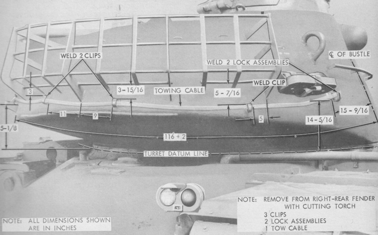
The towing cable usually stowed along the right fender was relocated to the turret rear, after new stowage clips were welded to the bustle. The water can bracket was also raised to make room for the towing cable. Inside the turret, the stove behind the oddment tray, and four ration boxes in the turret bustle were taken out. (Picture from TM 9-2590-206-15.)
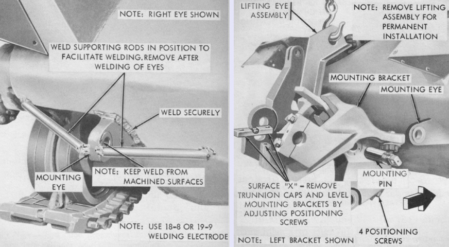
The towing lugs were removed to make room to weld mounting eyes for the hydraulic cylinder mounting brackets. The mounting eyes were temporarily secured to the hull with welded rod or strap, as seen on the left, before they were permanently welded to the hull. The mounting brackets were then secured to the mounting eyes via a lifting eye assembly that was removed after the brackets were secured. (Picture from TM 9-2590-206-15.)
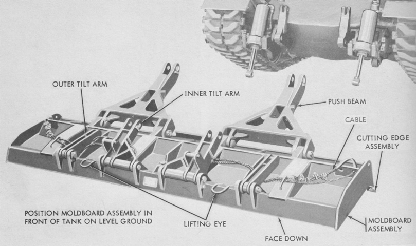
The moldboard is seen ready for installation. The push beams were connected to the hydraulic cylinder rams to raise or lower the moldboard, and the tilt arms connected to the mounting brackets on each side. (Picture from TM 9-2590-206-15.)
The hydraulic cylinders are shown mounted in their brackets, and the push beam has been connected on the right. (Picture from TM 9-2590-206-15.)
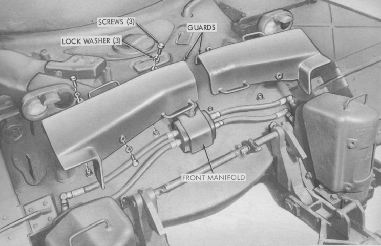
The hydraulic cylinders were connected to the oil supply via a manifold and tubing on the front hull that were protected by armor guards. (Picture from TM 9-2590-206-15.)
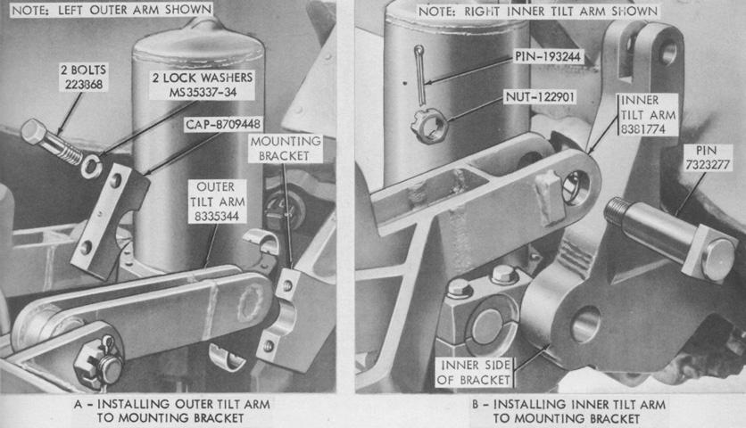
Tilt arms were connected on each side of the hydraulic cylinders. (Picture from TM 9-2590-206-15.)
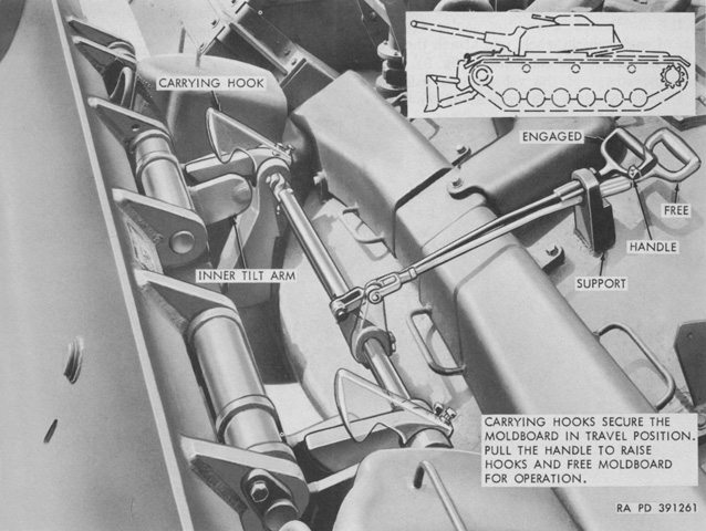
The moldboard was secured for travel by carrying hooks. The moldboard was raised a sufficient amount, then the driver reached down from his open hatch to push the carrying hooks handle forward. To release the moldboard, the handle was pulled to the rear. (Picture from TM 9-2590-206-15.)
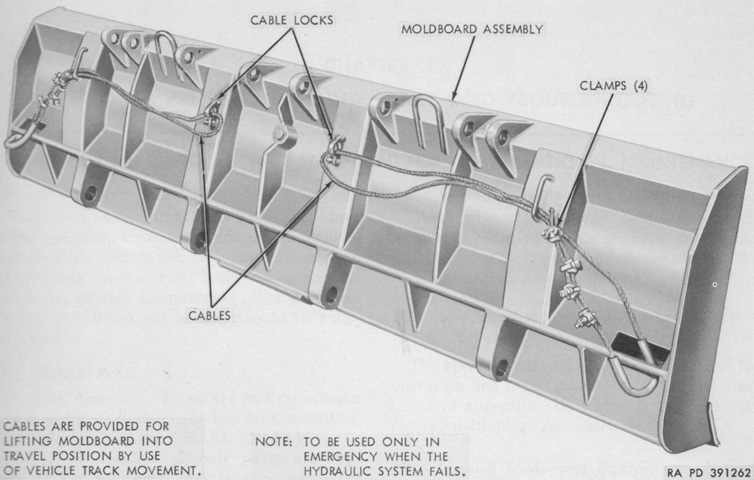
If the hydraulic system became inoperable, emergency cables were provided to ensure that the moldboard could be raised. The cables were stowed on the rear face of the moldboard. (Picture from TM 9-2590-206-15.)
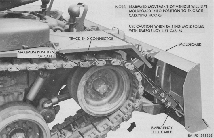
When needed, the cables were freed from their stowage locks and then looped around a track end connector. The moldboard control handle was placed in the F position, and the tank was then reversed until the moldboard was high enough to engage the carrying hooks. (Picture from TM 9-2590-206-15.)
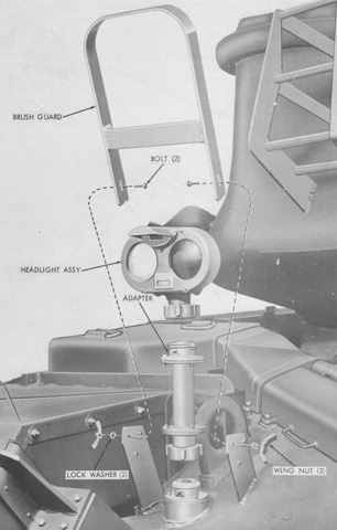
The headlight clusters were mounted atop adapters to ensure that their light projection could clear the raised moldboard. Taller brushguards were also used. (Picture from TM 9-2590-206-15.)
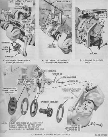
The installation of the hydraulic pump to the transmission's power take-off is illustrated here. Power flowed to the pump via a right-angle drive and a clutch that was actuated from the crew compartment. (Picture from TM 9-2590-206-15.)
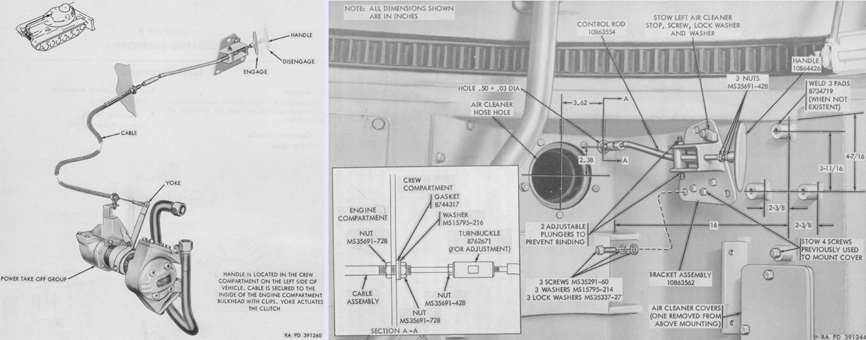
The clutch was engaged or disengaged by a handle at the left rear of the crew compartment. The handle's installation is shown on the right, with the engine air cleaner removed for clarity and room. (Picture from TM 9-2590-206-15.)
To accommodate servicing of the hydraulic pump assembly, a door was cut into the tank's transmission shroud and attached with hinges. (Picture from TM 9-2590-206-15.)
In addition, clearance needed to be ground away along the inside top of the right rear hull brake access cover as seen on the left, and on the right a section of the transmission rail had to be removed to make room for the mount assembly. (Picture from TM 9-2590-206-15.)
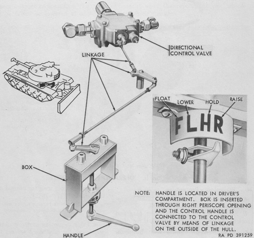
The moldboard control handle determined the moldboard method of operation. From left to right in the image, F was for float, where the moldboard would ride on the ground with only its weight providing downward pressure; L was for lowering the moldboard; H was for hold, which used hydraulic pressure to retain the moldboard at a specific position; and R was for raising the moldboard. The handle would automatically return to the H position from the R or L positions, and but handle would remain in the F or H positions until moved again by the operator. Additional effort was required for the handle to enter the F position. (Picture from TM 9-2590-206-15.)
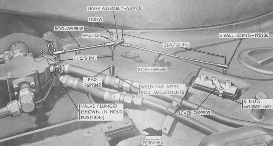
The moldboard control handle was installed in the driver's right periscope aperture, and this image shows its connections to the valve on the right front fender before the armor guards have been mounted. The vertical tubes on each side of lever-7699903 were attachment points for the control handle box's guard. (Picture from TM 9-2590-206-15.)
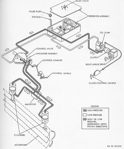
A schematic of the hydraulic system is sketched here. (Picture from TM 9-2590-206-15.)
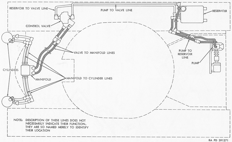
The hydraulic lines are shown in this image. (Picture from TM 9-2590-206-15.)
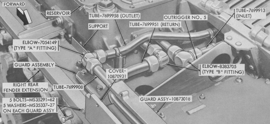
Connections to and guards around the reservoir are labeled in this image. (Picture from TM 9-2590-206-15.)
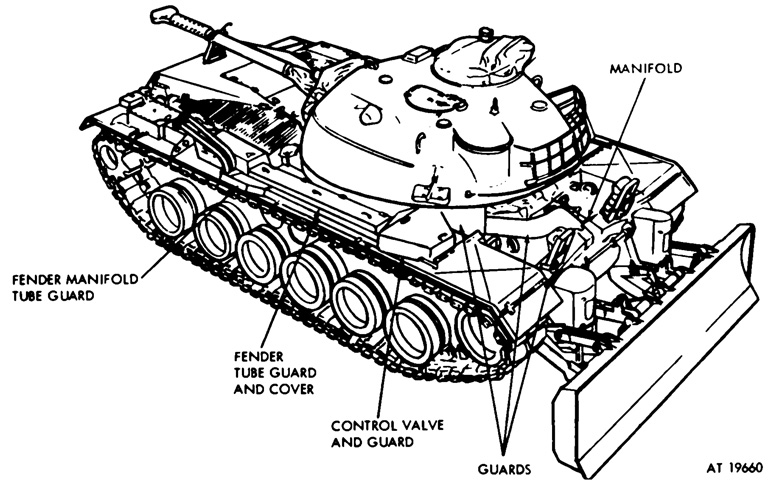
The M48A3 necessitated another revision, yielding the tank mounting bulldozer M8A3. It is drawn here installed on a tank with the hydraulic lines' armor guards labeled. Without the 15gal (57L) of hydraulic oil, the M8A3 weighed a total of 8,400lb (3,810kg), with the moldboard itself making up 3,004lb (1,323kg) of the total. The cutting edge angles to the ground were 59° in the float position and 65° in the lowest position. The cutting edge was 10" (25cm) below the ground in the lowest position, 30" (76cm) above the ground at the highest position, and 29" (74cm) above the ground in the carry position. (Picture from TM 9-2590-213-15 C1.)
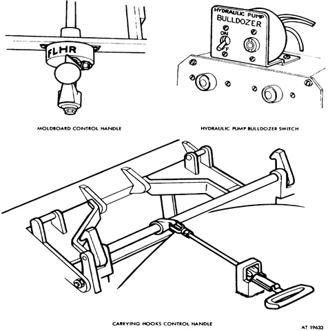
In contrast to earlier variants, the controls were all situated around the driver's compartment beginning with M8A3 serial number 59. The hydraulic pump bulldozer switch at the upper right was attached to the driver's instrument panel and engaged the hydraulic pump electromagnetic clutch. This replaced the clutch handle in the crew compartment found on M8A3 serial numbers up to 59 as well as on earlier variants of the bulldozer M8. The moldboard control handle and carrying hooks handle are familiar. (Picture from TM 9-2590-213-15 C1.)
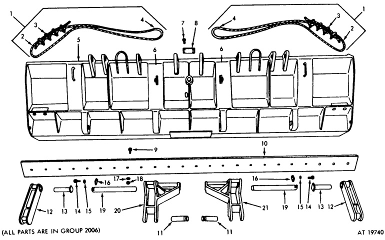
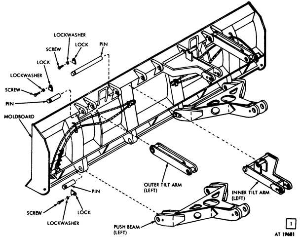
The rear of the moldboard and the tilt arms are drawn here. 1. Moldboard mechanical lifting cable assembly. 2. Moldboard cable rope. 3. Moldboard rope clamp. 4. Moldboard rope tube end. 5. Bulldozer blade assembly. 6. Moldboard cable stowage clamp assembly. 7. Bulldozer name plate screw. 8. Bulldozer name plate. 9. Cutting edge to moldboard bolt. 10. Bulldozer moldboard cutting edge. 11. Left and right moldboard tilt arm to bracket pin. 12. Moldboard front mounting bracket outer tilt arm assembly. 13. Left and right tilt arm to moldboard pin. 14. Left and right moldboard tilt arm to bracket (2) left and right tilt arm to moldboard (4) moldboard push beam to bracket (2) hexagon head cap screw. 15. Left and right moldboard tilt arm to bracket (2) left and right tilt arm to moldboard (4) moldboard push beam to bracket (2) lock washer. 16. Left and right moldboard tilt arm to bracket (2) left and right tilt arm to moldboard (4) moldboard push beam to bracket (2) lock. 17. Cutting edge to moldboard lock washer. 18. Cutting edge to moldboard nut. 19. Left and right tilt arm to moldboard pin. 20. Moldboard left inner tilt arm assembly. 21. Moldboard right inner tilt arm assembly. (Picture from TM 9-2590-213-15 C1.)
The moldboard and tilt arms are shown partially assembled here. The moldboard was 146" (371cm) long and 36" (91cm) tall. (Picture from TM 9-2590-213-15 C1.)
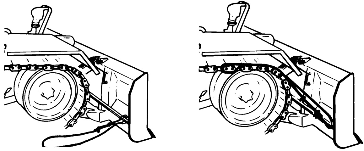
As before, when needed, the cables were freed from their stowage locks as seen on the left, and then looped around a track end connector as seen on the right. The moldboard control handle was placed in the F position, and the tank was then reversed until the moldboard was high enough to engage the carrying hooks. (Picture from TM 9-2590-213-15 C1.)
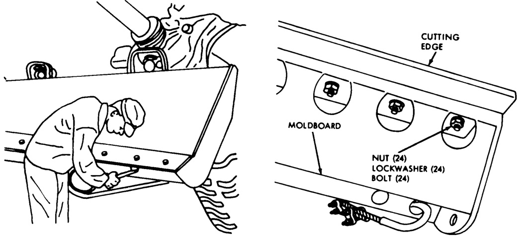
As on earlier versions of the M8 series, the reversible cutting edge could be replaced when necessary by unfastening 24 bolts secured with nuts and lockwashers. (Picture from TM 9-2590-213-15 C1.)
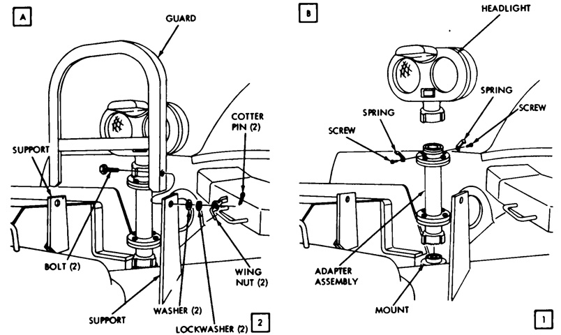
Extended headlight adapters and taller brushguards were carried over from earlier versions. (Picture from TM 9-2590-213-15 C1.)
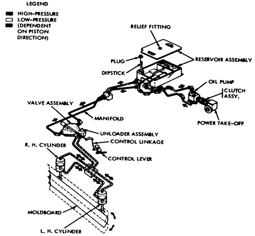
A schematic of the hydraulic system is sketched here. The power take-off utilized the tank's transmission, and the pump sent hydraulic power to the two cylinders on the hull front that lifted or lowered the moldboard. (Picture from TM 9-2590-213-15 C1.)
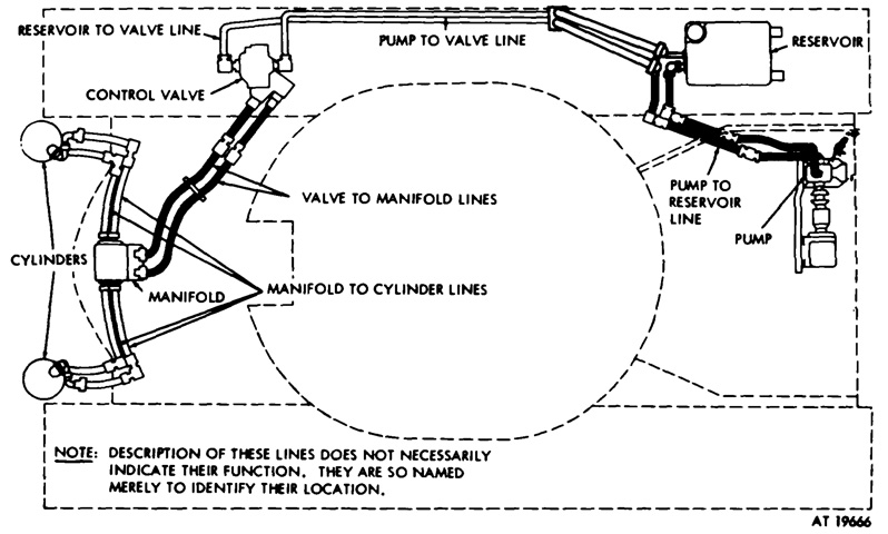
The layout of the hydraulic lines are detailed in this drawing, and can be contrasted to the M8A1's. (Picture from TM 9-2590-213-15 C1.)
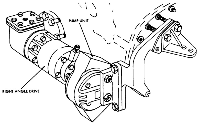
The hydraulic pump was attached to the power take-off at the rear of the transmission. A mounting bracket secured the assembly to the transmission, and power flowed to the pump through a right-angle drive and an electromagnetic clutch. (Picture from TM 9-2590-213-15 C1.)
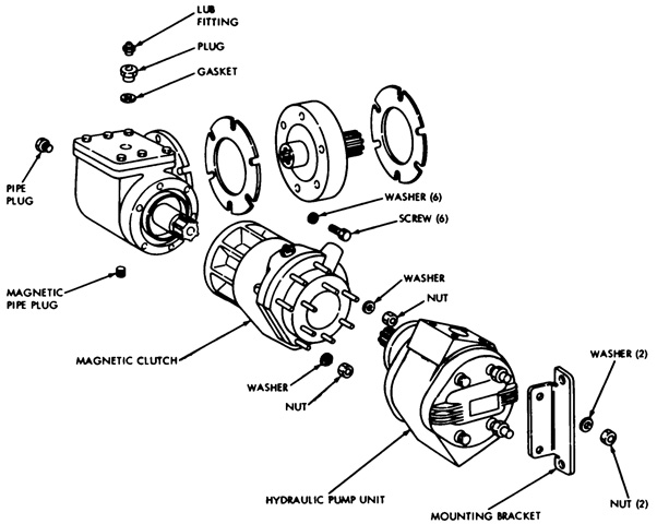
A partially disassembled view of the right angle drive (unlabeled), electromagnetic clutch, and hydraulic pump is provided here. (Picture from TM 9-2590-213-15 C1.)
The hydraulic reservoir was installed on the right rear fender behind the engine air cleaner. Note the hydraulic piping is elevated to clear the air cleaner. (Picture from TM 9-2590-213-15 C1.)
