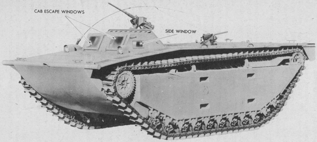
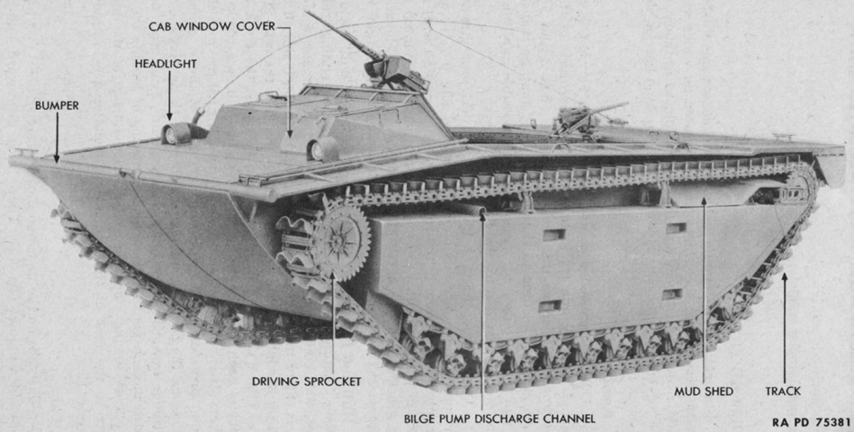
Landing Vehicle, Tracked, Mark 2.
Compared to its predecessor, the LVT1, the position of the LVT2's cab and the grouser shape are immediately differentiated. The running gear is another changed aspect, with the latter vehicle being equipped with idler sprockets in the rear, return rollers on top of the sponsons, and sprung road wheels. (Picture from TM 9-775 Landing Vehicle Tracked Mk. I and Mk. II.)
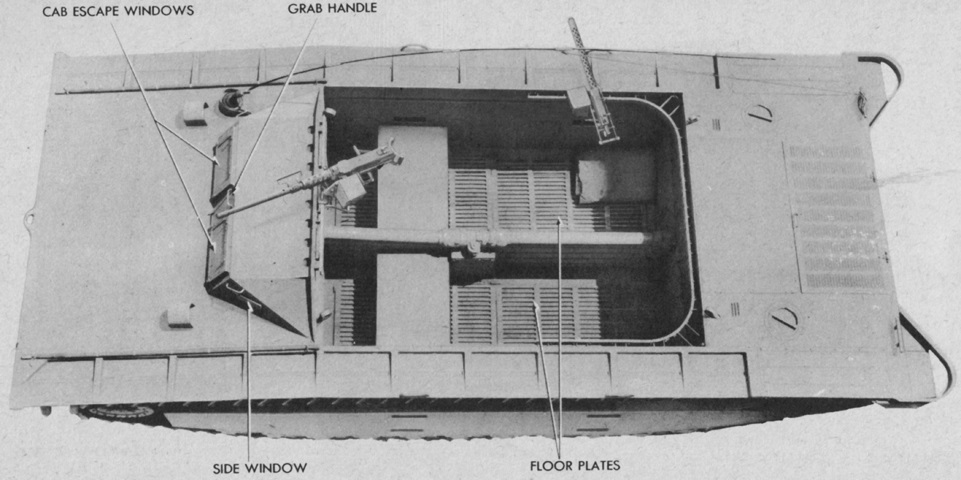
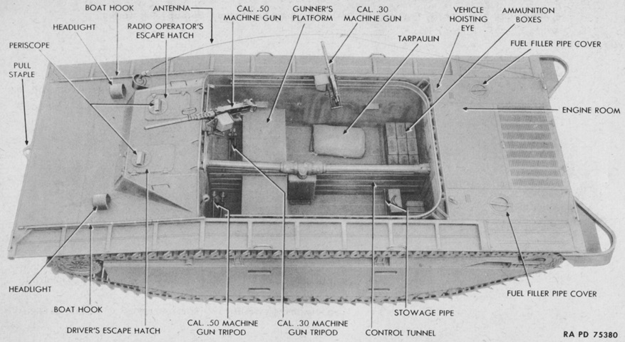
With the rear position of the engine, the disadvantageous requirement to load cargo and troops from over the side of the vehicle is obvious. The control tunnel bisecting the cargo compartment also reduced its utility. (Picture from TM 9-775 Landing Vehicle Tracked Mk. I and Mk. II.)
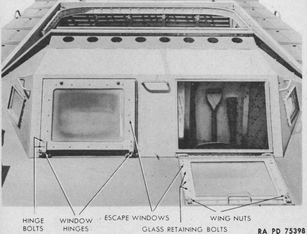
The cab escape windows were hinged on the bottom and rested on the front hull when open. Wing nuts secured them in the closed position, and grab handles at the top center of the frames facilitated opening and closing the windows. (Picture from TM 9-775 Landing Vehicle Tracked Mk. I and Mk. II.)
The cab cover could be dismounted, for instance in order to remove the transmission. The vehicle is shown here with the cab cover removed. (Picture from TM 9-775 Landing Vehicle Tracked Mk. I and Mk. II.)
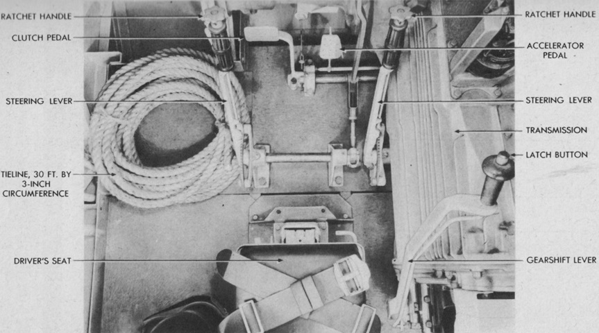
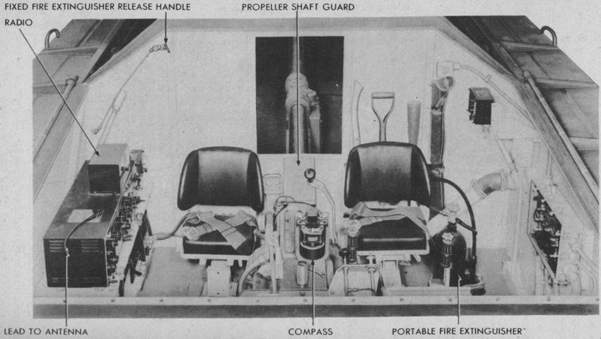
This view is looking forward into the driver's position. The seats were provided with aircraft-type quick-release safety belts. By turning the ratchet handles on top of the steering levers a quarter turn, a latch rod could be raised or lowered to lock the levers in any position. The latch on the gearshift lever prevented accidental shifting into first or reverse gears. (Picture from TM 9-775 Landing Vehicle Tracked Mk. I and Mk. II.)
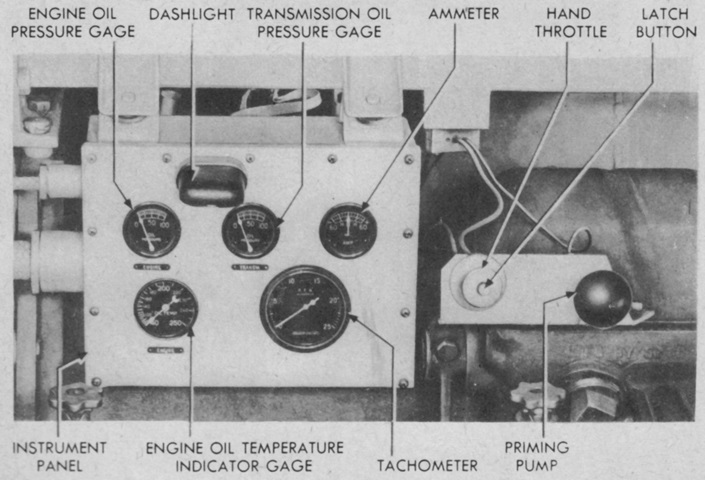
The driver's instrument panel was mounted directly to his front. (Picture from TM 9-775 Landing Vehicle Tracked Mk. I and Mk. II.)
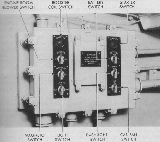
The driver's control panel was found to his left. (Picture from TM 9-775 Landing Vehicle Tracked Mk. I and Mk. II.)
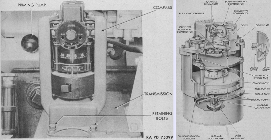
A compass was mounted to the driver's right on top of the transmission. It is shown above in position on the left and sectioned on the right. (Picture from TM 9-775 Landing Vehicle Tracked Mk. I and Mk. II.)
This image is of the rear of the cargo compartment with the rear bulkhead louvers removed, allowing us to see into the engine room. (Picture from TM 9-775 Landing Vehicle Tracked Mk. I and Mk. II.)
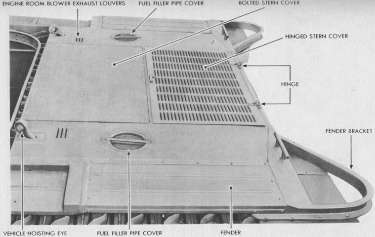
The rear deck is highlighted in this picture. (Picture from TM 9-775 Landing Vehicle Tracked Mk. I and Mk. II.)
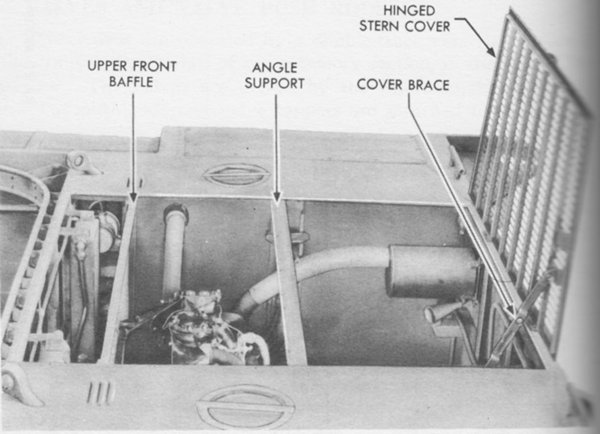
The rear deck is shown with the bolted stern cover removed and the hinged stern cover raised. (Picture from TM 9-775 Landing Vehicle Tracked Mk. I and Mk. II.)
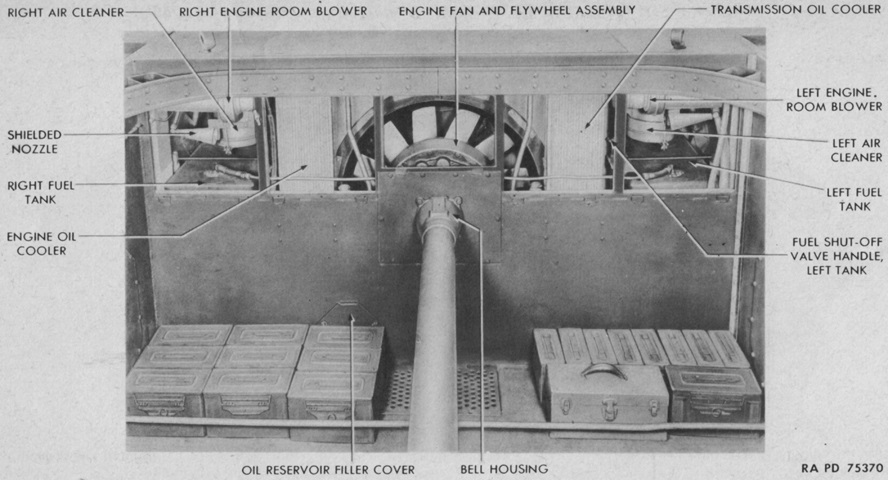
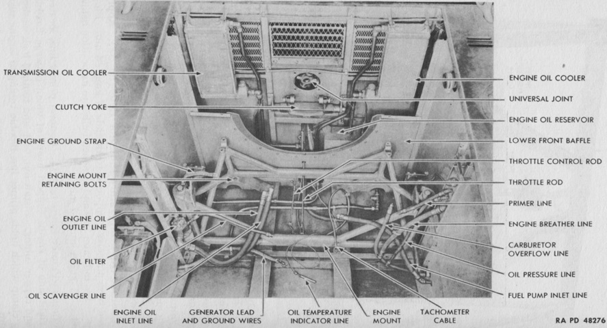
The engine room is illustrated here, looking towards the front of the vehicle. (Picture from TM 9-775 Landing Vehicle Tracked Mk. I and Mk. II.)
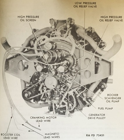
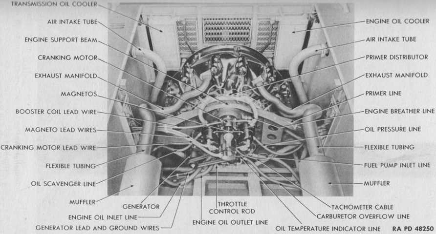
The engine is shown here from the right rear. It was shared with the gasoline-fueled versions of the light tank M3. (Picture from TM 9-775 Landing Vehicle Tracked Mk. I and Mk. II.)
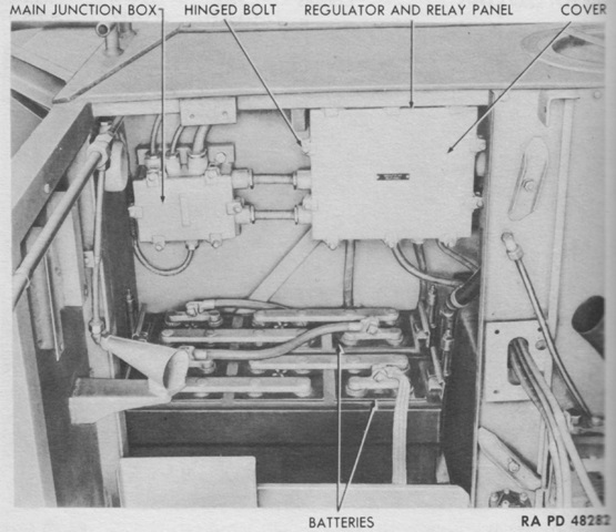
The engine room is seen from the rear with the engine removed. The vehicle's storage batteries are visible at the bottom left. (Picture from TM 9-775 Landing Vehicle Tracked Mk. I and Mk. II.)
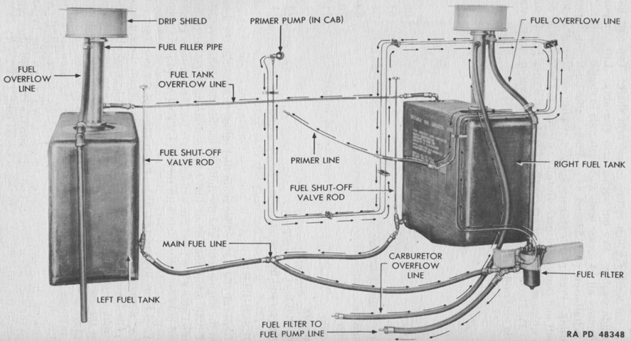
Two fuel tanks were mounted between the engine room and the hull. On the unarmored tractors, the fuel tanks were built by Terne Plate and made of steel, but on LVT(A)2 and LVT(A)1 the tanks were manufactured by Goodrich and were self-sealing. The left tank was located just ahead of the batteries, and the right tank could be found in front of the fixed fire extinguishers. A diagram of fuel flow is sketched here. (Picture from TM 9-775 Landing Vehicle Tracked Mk. I and Mk. II.)
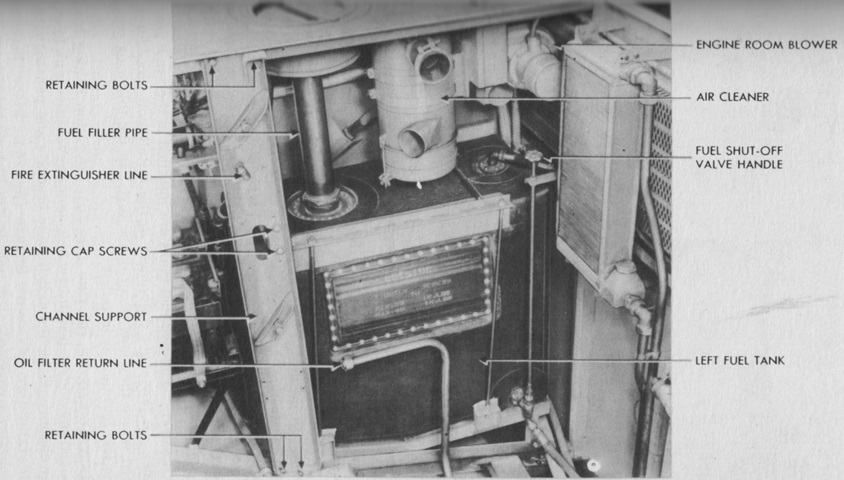
The left fuel tank compartment has been exposed. (Picture from TM 9-775 Landing Vehicle Tracked Mk. I and Mk. II.)
The battery compartment behind the left fuel tank has been opened by removing the upper and lower left engine room baffles. Two 6-volt storage batteries were connected in series to maintain a 12-volt system. (Picture from TM 9-775 Landing Vehicle Tracked Mk. I and Mk. II.)
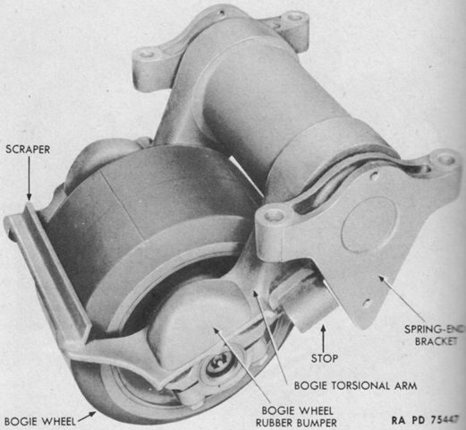
A suspension bogie is shown here. The torsilastic spring consisted of a hollow tube placed into a larger hollow tube with rubber vulcanized between them. The bogie wheel arms are welded to the outer shaft, and the spring end brackets, used to attach the assembly to the pontoon, are welded to the inner shaft. The outer shaft then rotates around the inner shaft with the rubber between them providing cushioning and support. (Picture from TM 9-775 Landing Vehicle Tracked Mk. I and Mk. II.)
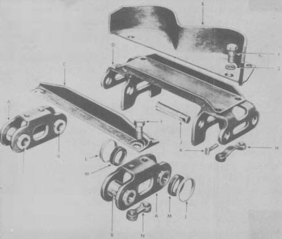
An exploded view of the tracks common to LVT2, LVT(A)2, LVT4, LVT(A)1, LVT(A)4, and LVT(A)5 is shown here. The inside and outside links combined for a pitch of 8" (20cm). The W-shaped cleats are welded to a baseplate which is then bolted to the drive chain. (Picture from Research, Investigation and Experimentation in the Field of Amphibian Vehicles.)
Removing the transmission first required removing the cab cover, which was attached with numerous screws, bolts, and nuts. (Picture from TM 9-775 Landing Vehicle Tracked Mk. I and Mk. II.)
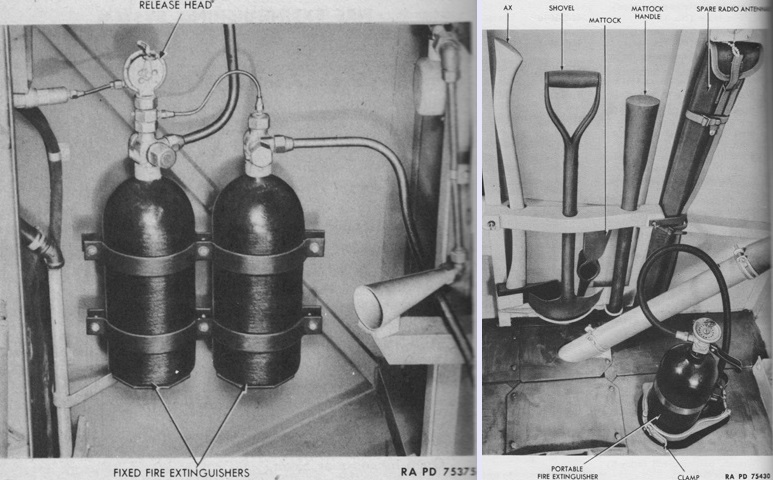
The fixed fire extinguisher system (left) included two 10lb (4.5kg) CO2 cylinders mounted behind the right fuel tank. Used to smother fires in the engine room, the cylinders were simultaneously actuated by either a handle in the cab behind the right seat or a handle at the right rear of the cargo compartment on the bulkhead. The engine was to be stopped if possible before using the extinguishers, but they could work on a fire with the engine running at up to 1,200rpm. The cylinders weighed 34.5lb (15.6kg) apiece when empty.
In addition, a portable 15lb (6.8kg) CO2 cylinder (right) was stowed to the driver's left rear. The cylinder weighed 38.5lb (17.5kg) when empty. (Picture from TM 9-775 Landing Vehicle Tracked Mk. I and Mk. II.)
The cab of this LVT(A)2 can be compared with the normal vehicle above. The windows have disappeared and have been replaced by armor plate and periscopes in the vehicle's roof. (Picture from TM 9-775 Landing Vehicle Tracked Mk. I and Mk. II.)

A rear view of the vehicle is shown here, including stowage of the towing cable. (Picture from TM 9-775 Landing Vehicle Tracked Mk. I and Mk. II.)
This view better shows the periscopes in the roof of the cab cover. (Picture from TM 9-775 Landing Vehicle Tracked Mk. I and Mk. II.)
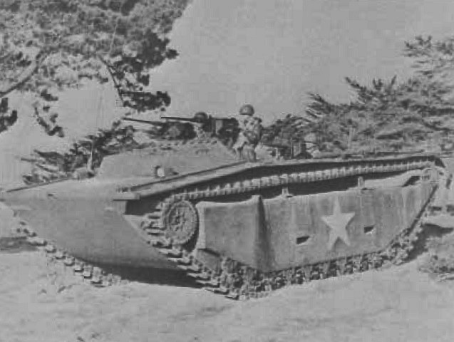
Though portions of the vehicle were now armored, the machine gunners were still forced to expose much of their bodies to employ their weapons. (Picture from Research, Investigation and Experimentation in the Field of Amphibian Vehicles.)
