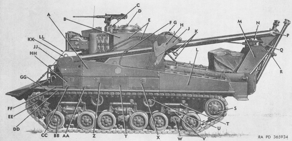
Medium Tank Recovery Vehicle M74.
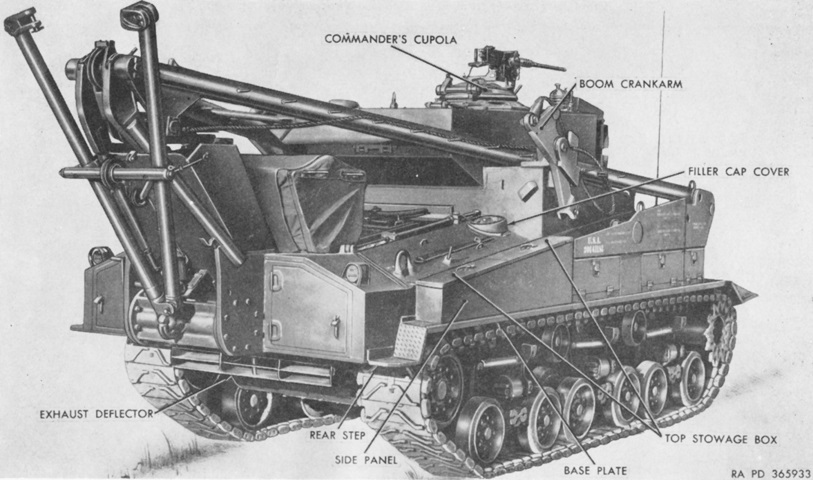
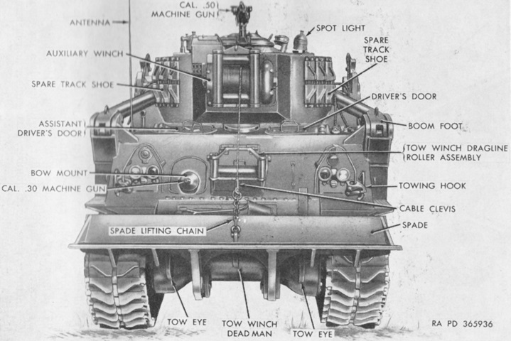
The M4A3 Sherman basis of the M74 is apparent when the hull shape and running gear are examined. A. Boom cylinder cover. B. (Fixed) turret. C. Cal. .50 machine gun mount. D. Commander's vision cupola. E. Tow cable. F. Stayline clamp. G. Boom stayline cable. H. Crank arm pivot pin. J. Boom crank arm. K. Tow cable link. L. Top stowage box. M. Oxygen and acetylene cylinder stowage compartment. N. Stayline frame. P. Boom end. Q. Stayline sheave pin. R. Turnbuckle. S. Track idler. T. Shock absorber. U. Double track support roller. V. Spring. W. Suspension arm support. X. Rear side stowage box. Y. Cylinder access cover. Z. Center side stowage box. AA. Hinge angle. BB. Road wheel. CC. Hinge. DD. Left front base. EE. Track drive sprocket. FF. Front tread plate. GG. Front fender. HH. Front side stowage box. JJ. Pin retainer. KK. Boom lifting eye. LL. Auxiliary winch cable. (Picture from TM 9-7402 Operation and Organizational Maintenance Medium Tank Recovery Vehicle M74.)
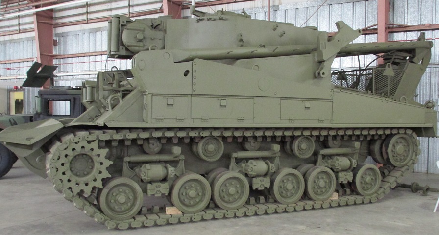
The stabilizing spade/dozer blade is in the retracted position to the vehicle's front, and the A-frame boom is stowed to the rear. The auxiliary winch is visible on the front of the turret, and the socket for mounting a .50cal machine gun on the commander's cupola can be seen pointing toward the front of the vehicle. The boom on the M74 was raised via hydraulic cylinders, in contrast to earlier tank recovery vehicles, which allowed it to be used as a live boom. The fenders over the tracks had a generous amount of stowage boxes mounted on them.
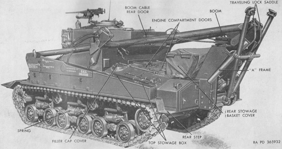
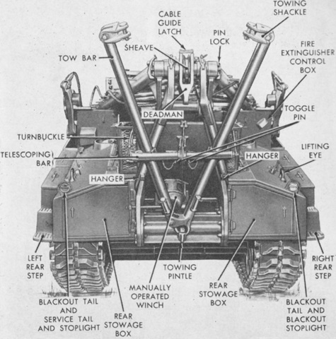
Features of the vehicle's left rear are labeled. (Picture from TM 9-7402 Operation and Organizational Maintenance Medium Tank Recovery Vehicle M74.)
The stowed boom overlapped the large stowage basket on the hull rear.
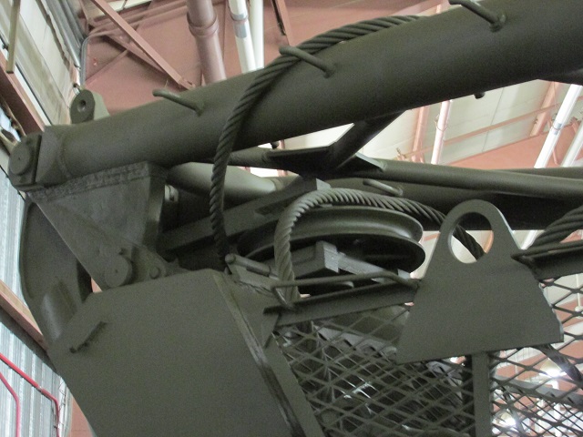
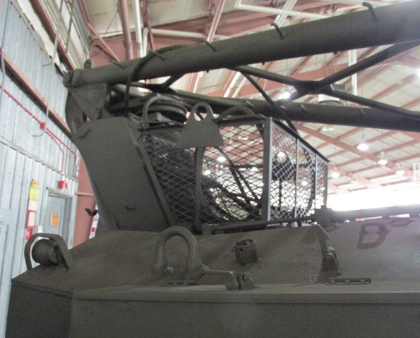
Further details of the stowed boom can be seen in this picture.
The right rear of the vehicle is shown in this picture. (Picture from TM 9-7402 Operation and Organizational Maintenance Medium Tank Recovery Vehicle M74.)
External handles for activating the fire extinguishers are on the right side of the rear superstructure, and the rear cable boom door can be seen at the back of the turret from this angle.
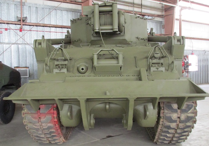
The vehicle is seen here from the rear. (Picture from TM 9-7402 Operation and Organizational Maintenance Medium Tank Recovery Vehicle M74.)
The boom is stowed to the rear, with the A-frame and traversing lock saddle providing support. The tow bar, pulley, and manual winch typically found on and within the A frame are absent on this machine.
The left rear step and stowage box can be seen here. Note also that the air intake grilles on the hull rear deck have been fitted with torsion bars to make opening and closing easier.
The front of the vehicle is shown here. (Picture from TM 9-7402 Operation and Organizational Maintenance Medium Tank Recovery Vehicle M74.)
The bow machine gun was retained, and the cable in the turret-mounted auxiliary winch is visible here.
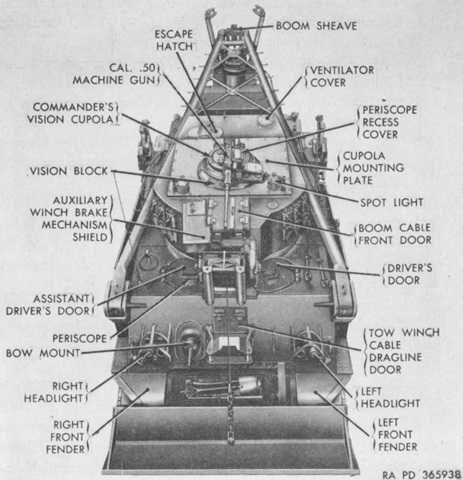
The vehicle is seen from above. Note that the commander's cupola was attached to a removable mounting plate. (Picture from TM 9-7402 Operation and Organizational Maintenance Medium Tank Recovery Vehicle M74.)
A view into the interior is provided with the cupola mounting plate removed. (Picture from TM 9-7402 Operation and Organizational Maintenance Medium Tank Recovery Vehicle M74.)
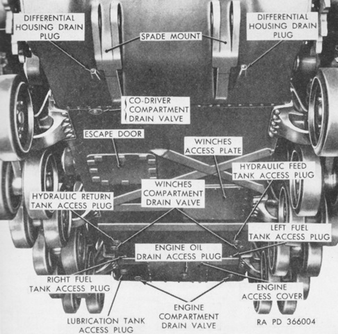
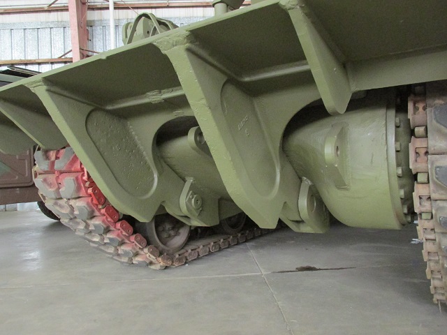
The hull underside had winch and hydraulic system access plates in addition to the normal drains and automotive access plates. The attachment of HVSS bogies to the hull underside can also be seen. (Picture from TM 9-7402 Operation and Organizational Maintenance Medium Tank Recovery Vehicle M74.)
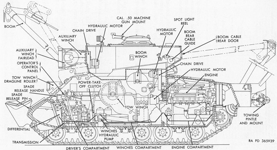
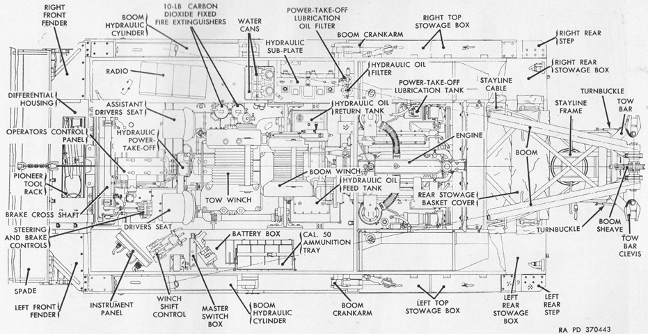
The interior layout is sketched in this cross-section. (Picture from TM 9-7402 Operation and Organizational Maintenance Medium Tank Recovery Vehicle M74.)
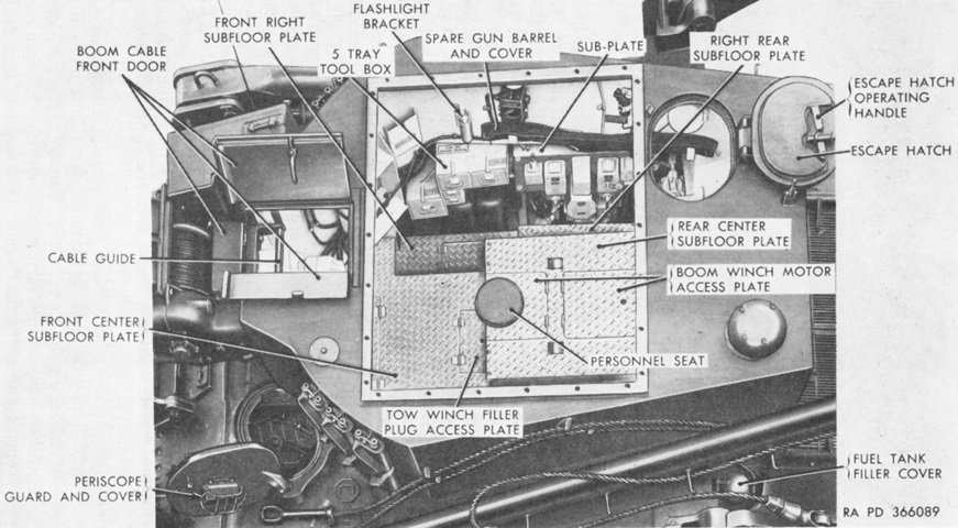
This drawing is a sectionalized view from above. (Picture from TM 9-7402 Operation and Organizational Maintenance Medium Tank Recovery Vehicle M74.)
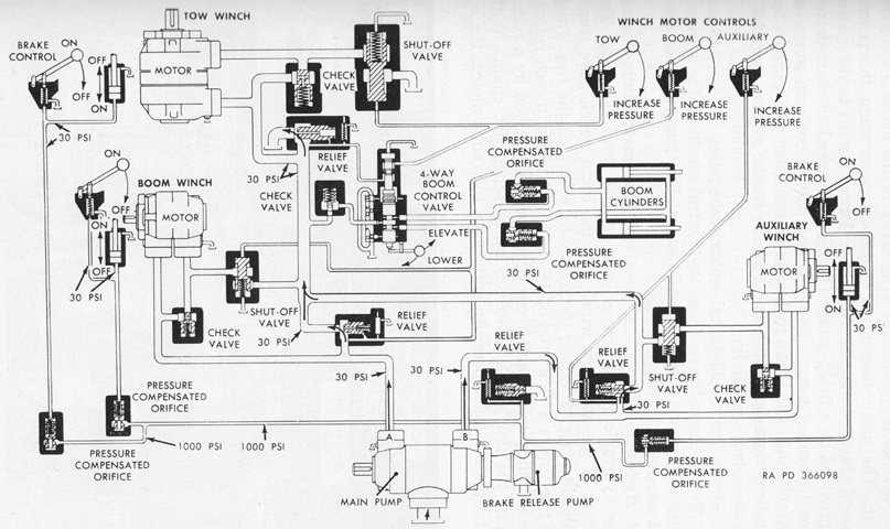
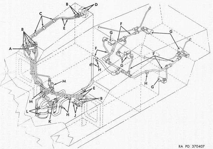
The idling hydraulic system is diagrammed in this schematic. The hydraulic system supplied power for control and operation in releasing the winch brakes, which were mechanically applied by heavy coil springs; for the three winches; and for the boom. The winch hydraulic (main) pump was chain-driven from the power take-off clutch. The winch brake system was powered by a brake pump which was chain driven from the winch pump. Both the winch and brake systems used the same source of hydraulic oil. For the boom, with none of the winch motors running or with the system idling, hydraulic oil would flow through the pilot system of the tow winch relief valve and pass through a section of the boom control valve on its way to the tow winch motor pilot valve. Elevating the boom stopped the flow through the valve, and the pressure buildup closed the tow winch release valve. Oil would pass through the boom control valve through a regulator and into the boom cylinders. (Picture from TM 9-7402 Operation and Organizational Maintenance Medium Tank Recovery Vehicle M74.)
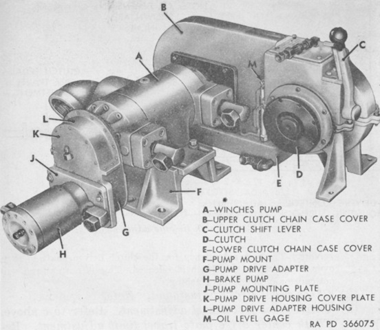
Seen on the assistant driver's side of the propeller shaft below is the power-take-off clutch shift lever. When this lever was engaged, power was transmitted from the engine to the winch pump via a sliding-jaw type power-take-off. A drive sprocket on the power-take-off drove a roller chain over a sprocket at the end of the main hydraulic pump shaft. (Picture from TM 9-7402 Operation and Organizational Maintenance Medium Tank Recovery Vehicle M74.)
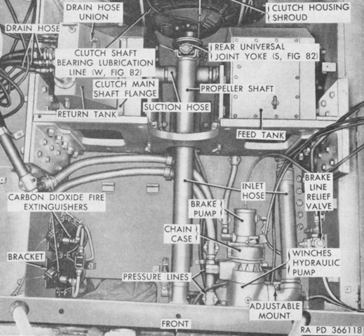
The winches and brake pumps are at the lower right of this image, and the hydraulic tanks are mounted on either side of the engine propeller shaft near the rear bulkhead at the top of the image. (Picture from TM 9-7402 Operation and Organizational Maintenance Medium Tank Recovery Vehicle M74.)
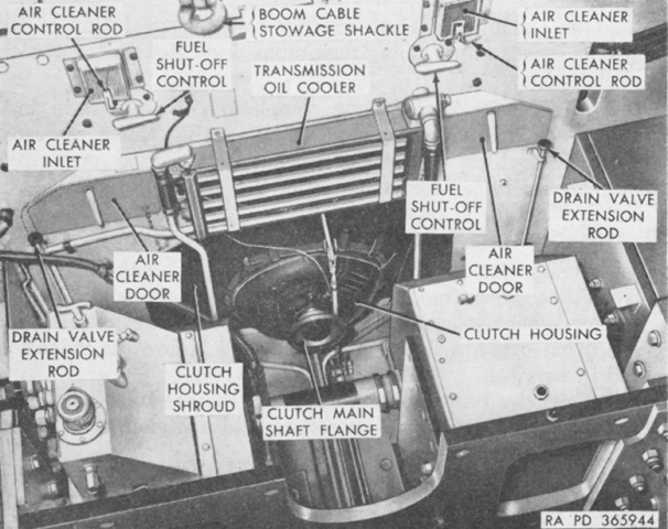
A closer look at the engine compartment bulkhead is given in this picture. The hydraulic tanks are unlabeled, and the engine propeller shaft has been removed. (Picture from TM 9-7402 Operation and Organizational Maintenance Medium Tank Recovery Vehicle M74.)
The drivers' hatches, periscope guards, and cover over the hull ventilator opening can be seen in this image.
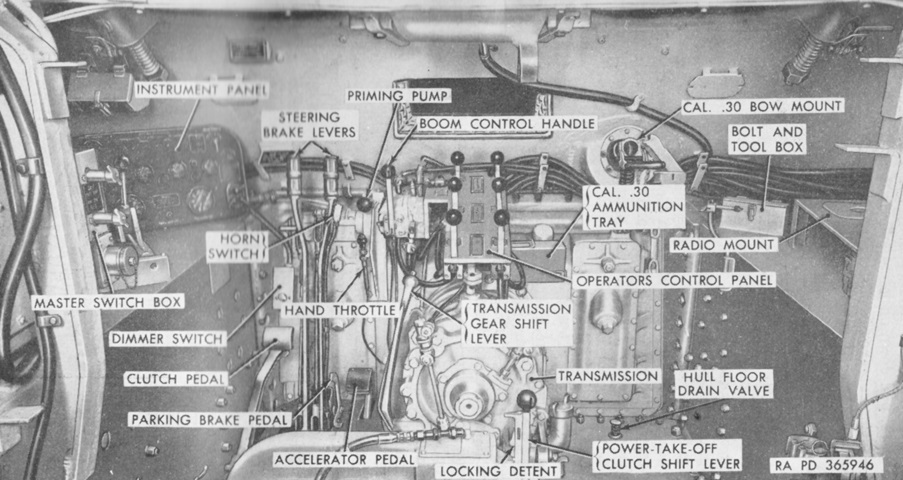
The drivers' positions can be seen in this picture. The .30cal bow machine gun remained, and a cutout in the upper front hull plate provided an exit for the tow winch cable. The T-shaped spade release handle is unlabeled, but is located in front of the steering levers. (Picture from TM 9-7402 Operation and Organizational Maintenance Medium Tank Recovery Vehicle M74.)
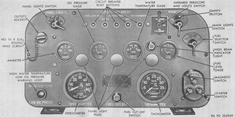
The driver's instrument panel is labeled in this picture. (Picture from TM 9-7402 Operation and Organizational Maintenance Medium Tank Recovery Vehicle M74.)
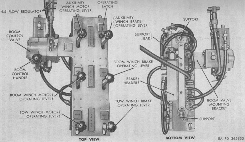
The top and bottom of the operator's control panel are illustrated in these images. The boom control handle elevated the boom when pushed forward, lowered the boom when pulled to the rear, and would spring to a central neutral position when released. The auxiliary winch motor operating lever, boom winch operating lever, and tow winch operating lever would increase the speed of the affected winches when pulled to the rear, and would spring to the off position when released. The auxiliary winch brake operating lever, boom winch brake operating lever, and tow winch brake operating lever released the affected winch brake when pulled to the rear, and would spring to the on position when released. The auxiliary winch brake operating lever also had a locking latch to hold the lever back. A sharp blow to the lever would send it forward to the on position, and a power failure would automatically apply the brake. (Picture from TM 9-7402 Operation and Organizational Maintenance Medium Tank Recovery Vehicle M74.)
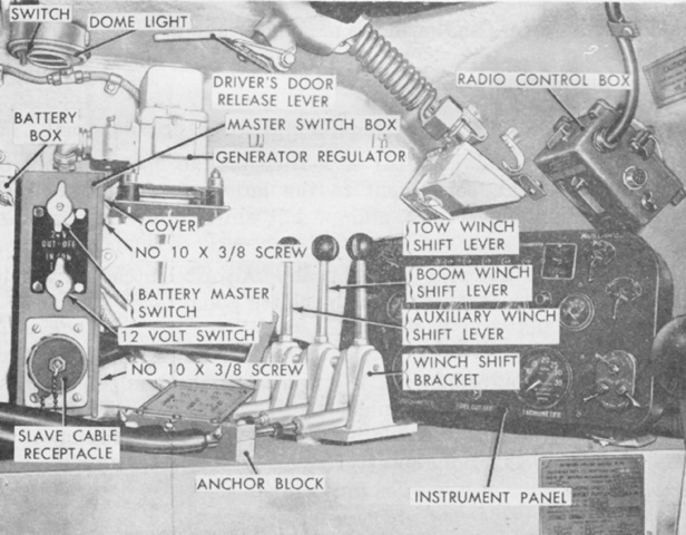
The left side of the driver's position is highlighted here. The tow winch shift lever would pay out cable when pulled back and pay in cable when pushed forward; it would return to neutral when released. The boom and auxiliary winch shift levers worked in an identical manner. (Picture from TM 9-7402 Operation and Organizational Maintenance Medium Tank Recovery Vehicle M74.)
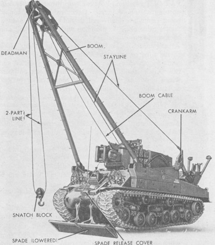
The vehicle is shown here prepared for a lifting operation. The boom could safely handle loads of 50,000lb (23,000kg) and, when elevated, was secured by a 45' (14m) long, 1-⅓" (3.4cm) thick stayline that was attached to pivot-mounted crank arms on the hull. (Picture from TM 9-7402 Operation and Organizational Maintenance Medium Tank Recovery Vehicle M74.)
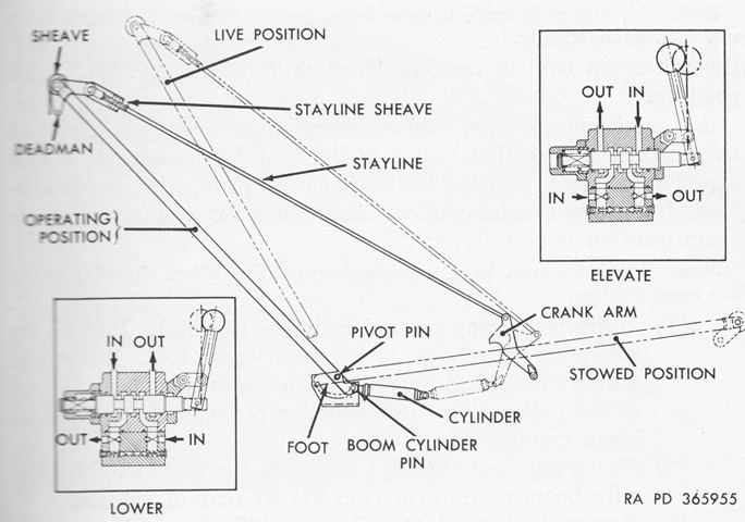
The boom could be used in the stowed position, or elevated to either the operating or live positions. As a live boom, the elevation angle could be changed to move the load 3-4' (.9-1.2m) closer to the vehicle. (Picture from TM 9-7402 Operation and Organizational Maintenance Medium Tank Recovery Vehicle M74.)
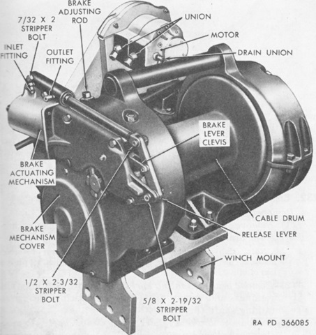
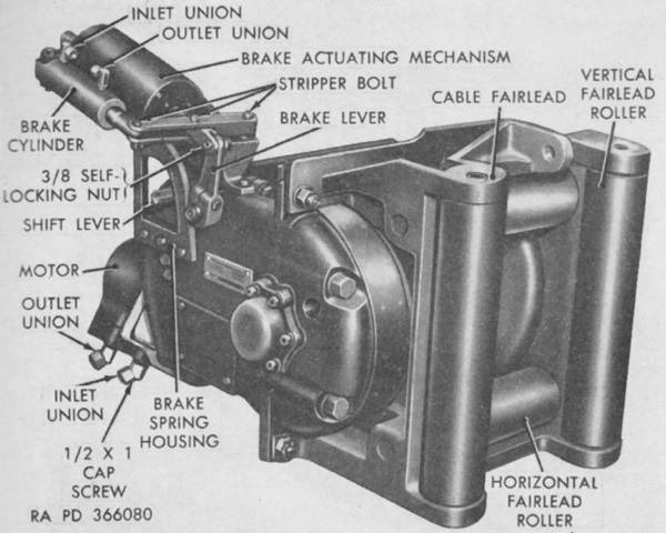
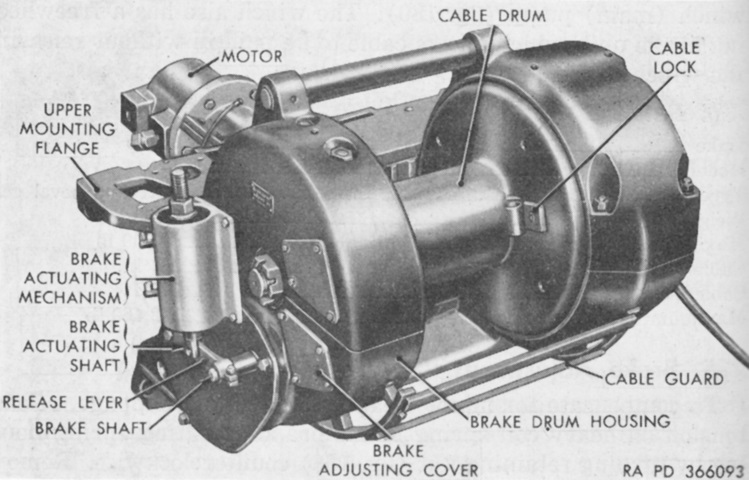
The boom winch was a Carco F series 6 spur and bevel gear type, seen here from the right front. It was chain driven by a motor operated by pressure from the winches pump. The brake actuating mechanism was preset to 1,200psi (84kg/cm²), and the brake mechanism freewheeled on pay in so that the cable could be retracted without operating the brake operating lever. (Picture from TM 9-7402 Operation and Organizational Maintenance Medium Tank Recovery Vehicle M74.)
The boom winch weighed 1,656lb (751.2kg) with its cable, and was chain driven by a motor operated by pressure from the winches pump. (Picture from TM 9-7402 Operation and Organizational Maintenance Medium Tank Recovery Vehicle M74.)
Looking into the turret interior with the floor plates removed, the boom winch is visible in the upper half of the picture. Part of the tow winch can also be seen at the bottom. (Picture from TM 9-7402 Operation and Organizational Maintenance Medium Tank Recovery Vehicle M74.)
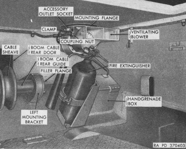
The boom cable rear door and cable guide can be seen in this left-rear view of the turret, as well as a 5lb (2.3kg) portable CO2 fire extinguisher and the ventilating blower. A similar fire extinguisher was also mounted in front of the assistant driver's seat. (Picture from TM 9-7402 Operation and Organizational Maintenance Medium Tank Recovery Vehicle M74.)
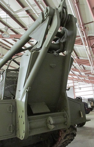
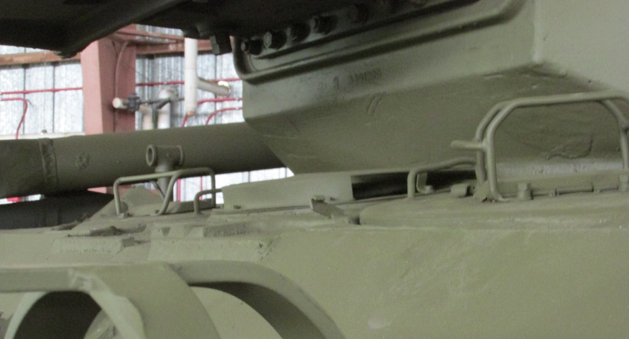
An external view of the boom cable rear door is provided here.
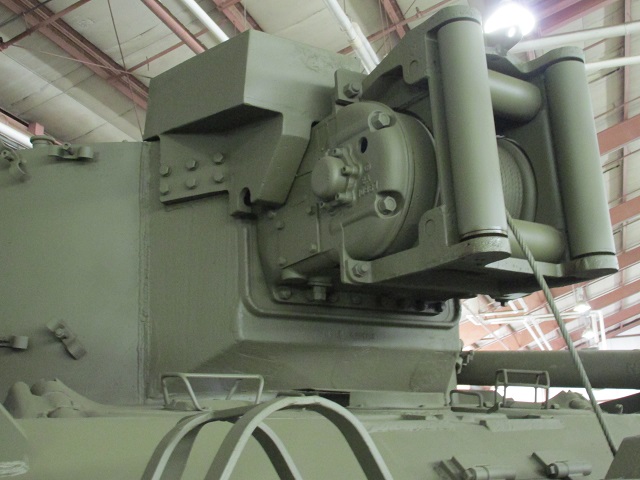
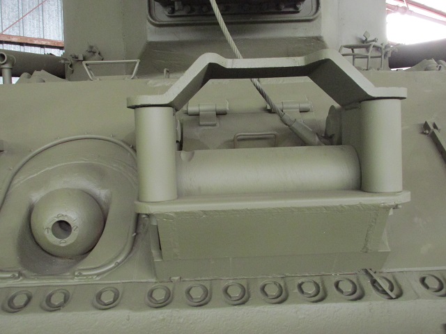
A closer look at the auxiliary winch is provided in this picture.
The auxiliary winch was a Carco E spur and bevel gear type, seen here from the right front. Its brake could only be released by using the brake operating lever. (Picture from TM 9-7402 Operation and Organizational Maintenance Medium Tank Recovery Vehicle M74.)
The auxiliary winch weighed 1,132lb (513.5kg) with the cable, and was chain driven from a motor that received hydraulic pressure from the winches pump. (Picture from TM 9-7402 Operation and Organizational Maintenance Medium Tank Recovery Vehicle M74.)
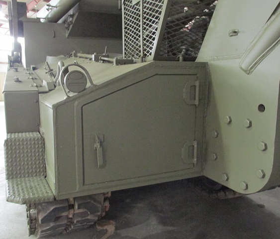
Attachment points for the spade were welded to the underside of the final drive and differential cover. It was used to stabilize the vehicle when loads of more than 15,000lb (6,800kg) were to be hoisted or winched, and it could also be used for bulldozing work. The auxiliary winch was used to raise and lower the spade.
More details of the mounting of the spade are provided here.
The interior of the turret front is shown here, with the auxiliary winch mounted. (Picture from TM 9-7402 Operation and Organizational Maintenance Medium Tank Recovery Vehicle M74.)
This is the left-front corner of the turret. The spotlight was installed in the cupola mounting plate. (Picture from TM 9-7402 Operation and Organizational Maintenance Medium Tank Recovery Vehicle M74.)
The sturdy mounting for the tow winch leads can he seen here, with an access door visible in the hull plate behind the rollers.
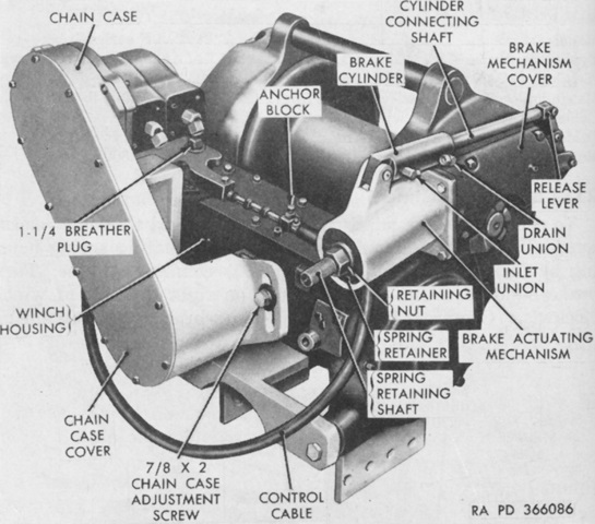
The Carco J-10 spur and bevel gear tow winch is shown here from the right front. Its brake unit was freewheeling so that the brake operating lever did not have to be actuated to pay in cable. (Picture from TM 9-7402 Operation and Organizational Maintenance Medium Tank Recovery Vehicle M74.)
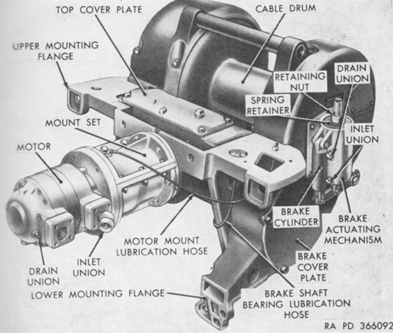
The tow winch was chain driven by an hydraulically operated motor that received pressure from the winch (main) pump. It weighed 3,750lb (1,700kg) with cable. (Picture from TM 9-7402 Operation and Organizational Maintenance Medium Tank Recovery Vehicle M74.)
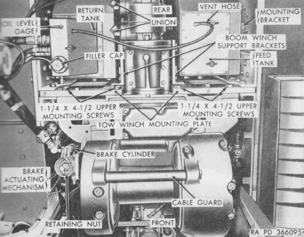
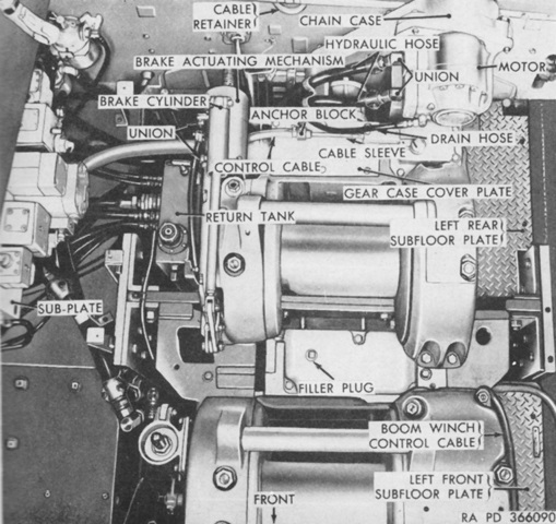
The tow winch is shown here installed; the tow winch mounting plate extended across the hull floor. The hydraulic tanks are at the top of the image. (Picture from TM 9-7402 Operation and Organizational Maintenance Medium Tank Recovery Vehicle M74.)
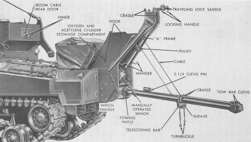
The tow bar was supported by the towing pintle and stowed alongside the A frame at the vehicle rear. The cable from the manually-operated winch and two turnbuckles that latched to the oxygen and acetylene cylinder stowage compartment secured the tow bar when not in use. After the turnbuckles were released, the winch was used to lower the tow bar to the required height. (Picture from TM 9-7402 Operation and Organizational Maintenance Medium Tank Recovery Vehicle M74.)
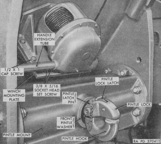
The manually operated winch had a 20.1 handle to drum ratio and used 26.5' (8.08m) of cable. (Picture from TM 9-7402 Operation and Organizational Maintenance Medium Tank Recovery Vehicle M74.)
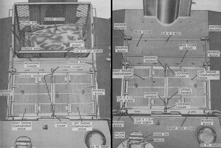
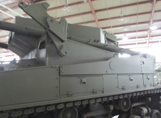
The rear deck is shown here with and without the stowage basket. Access to the radiator and fan shroud assembly could be obtained by lifting the rear covers after the stowage basket had been dismounted. Note that, in contrast to a typical medium tank, the right and left engine compartment doors were hinged in the middle so that they could be opened with the boom in the stowed position. (Picture from TM 9-7402 Operation and Organizational Maintenance Medium Tank Recovery Vehicle M74.)
The engine compartment doors are open on this machine, showing the utility of the hinges with the boom stowed. The tracks on the vehicle's turret are rubber-block T84.
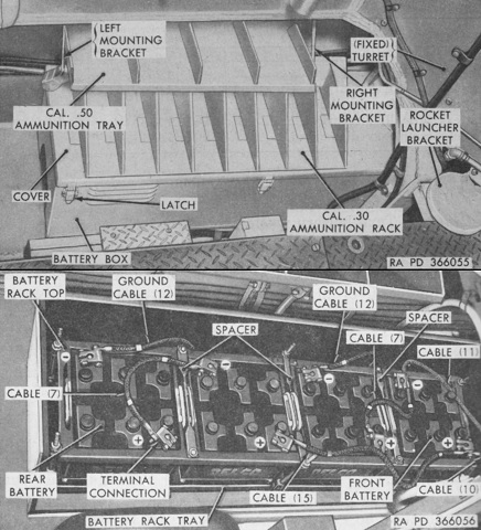
The battery box was located in the left sponson behind the master switchbox. It is shown closed in the top image and open below. The battery box was constructed so that either two 8TN 12-volt batteries or four 6TN 12-volt batteries could be installed. The two batteries would be connected in series and the four in series parallel to total 24 volts. (Picture from TM 9-7402 Operation and Organizational Maintenance Medium Tank Recovery Vehicle M74.)
The headlight mounting with its heavy-duty guard is highlighted here. Steps were built into the front and rear of each fender.
The fixed fire extinguisher system consisted of two 10lb (4.5kg) CO2 cylinders mounted behind the assistant driver's seat. The cylinders were routed to discharge into the engine and fuel compartments. The system could be actuated via the cylinders' control heads, by handles on the hull roof above the driver, or by handles on the turret right rear. A. Dual pull mechanism. B. Coupling nut. C. Clamp. D. Outside pull handle. E. Cable conduit. F. Discharge tube. G. Nozzle. H. Clamp. J. Inside pull handle. K. Check valve. L. ⅜ x 2¼ cap screw. M. Remote control. (Picture from TM 9-7402 Operation and Organizational Maintenance Medium Tank Recovery Vehicle M74.)
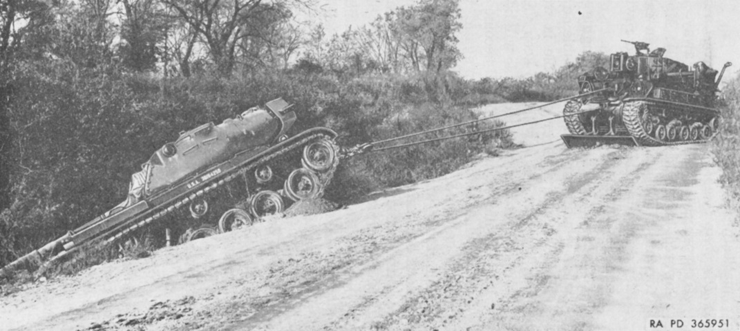
Recovery of a 90mm gun tank M47 is depicted here. The stabilizing spade is deployed, and a 2-part line is being employed with a snatch block 19-B-33435. (Picture from TM 9-7402 Operation and Organizational Maintenance Medium Tank Recovery Vehicle M74.)
