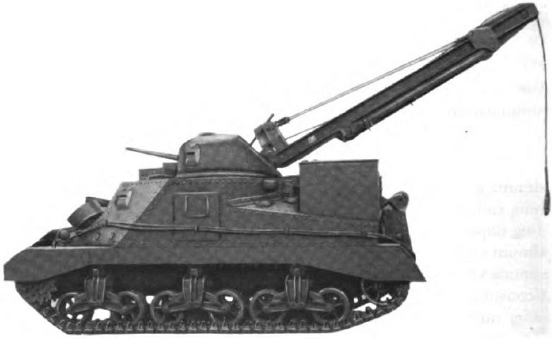
Tank Recovery Vehicle M31.

The large crane boom emanating from the front of the turret identifies this vehicle as an M31. Disguise was attempted, however: a dummy 37mm gun barrel attached to the turret rear and a dummy 75mm gun conspired to convince the enemy that this was a regular tank. When stowed, the crane boom would assume a more horizontal position. Stowage boxes are mounted on the rear, and tow cables snake along the hull side. (Picture from TM 9-2800 Standard Military Motor Vehicles.)
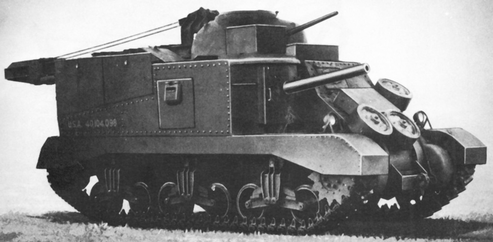
The crane boom is stowed, and spare road wheels are mounted on pegs on the hull front. The dummy 75mm gun was attached to a door, the handle of which can be seen outboard of the gun tube. Stowage boxes are present on the front hull roof as well. (Picture from Catalogue of Standard Ordnance Items, second edition 1944, volume I: Tank and Automotive.)
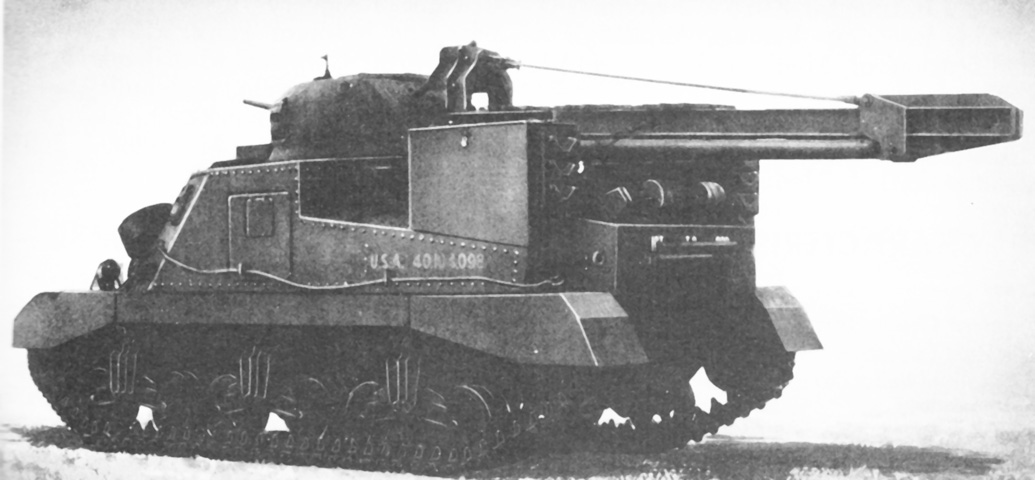
The crane boom extended well to the rear when stowed, and a boom jack leg is visible on the underside of the boom. These jacks could be emplaced on the ground or on the two support angles visible on the upper rear hull. (Picture from Catalogue of Standard Ordnance Items, second edition 1944, volume I: Tank and Automotive.)
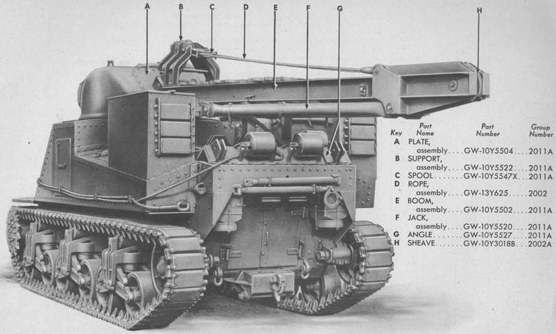
Parts of the stowed crane boom are labeled. The support angles for the jacks are better seen here outboard of the spare return roller stowage on the upper rear hull. (Picture from ORD 7-8-9 SNL G-169 C2 Organizational Spare Parts and Equipment, Higher Echelon Spare Parts and Equipment (Addendum) Service Parts Catalog for Vehicle, Tank Recovery, M31 (T2) (Tank, Medium, M3, w/Crane).)
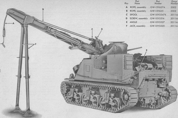
The support jacks are shown deployed on the ground. Detachable feet were used to stabilize the jacks during ground use. (Picture from ORD 7-8-9 SNL G-169 C2 Organizational Spare Parts and Equipment, Higher Echelon Spare Parts and Equipment (Addendum) Service Parts Catalog for Vehicle, Tank Recovery, M31 (T2) (Tank, Medium, M3, w/Crane).)
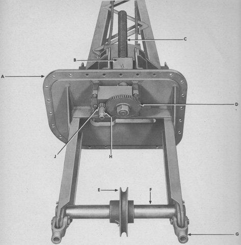
The interior of the crane mounting plate on the turret front is detailed in this image, revealing the boom adjusting screw and fleeting sheave assemblies. A. Plate, assembly. B. Trunnion, assembly. C. Screw, assembly. D. Gear. E. Sheave, assembly. F. Shaft, assembly. G. Yoke, assembly. H. Adapter, assembly. J. Pinion. (Picture from ORD 7-8-9 SNL G-169 C2 Organizational Spare Parts and Equipment, Higher Echelon Spare Parts and Equipment (Addendum) Service Parts Catalog for Vehicle, Tank Recovery, M31 (T2) (Tank, Medium, M3, w/Crane).)
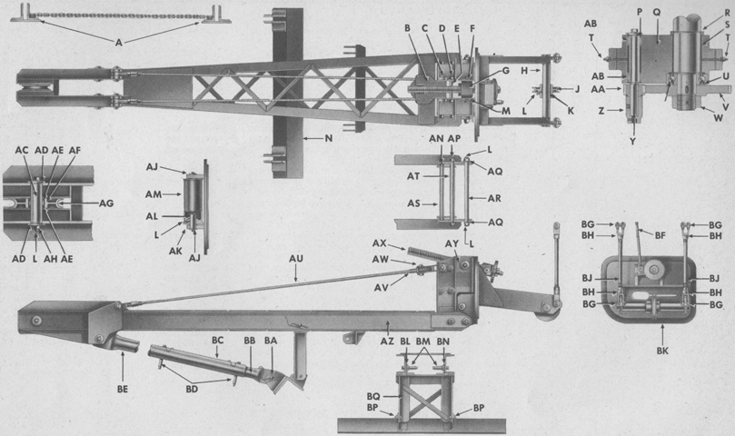
Components of the crane assembly are shown here. A. Foot, assembly. B. Frame, assembly. C. Pin; washer; pin. D. Rod; nut; washer. E. Spacer. F. Washer; screw; washer. G. Trunnion, assembly (includes F and T). H. Shaft. J. Sheave, assembly (includes K and L). K. Bushing. L. Fitting. M. Washer; screw; washer. N. Angle. P. Washer; screw; washer. Q. Trunnion, assembly. R. Spacer. S. Bushing. T. Fitting. U. Spacer. V. Gear. W. Nut; pin. X. Bearing. Y. Pin, assembly (includes P). Z. Adapter, assembly. AA. Pinion. AB. Bearing. AC. Pin, assembly (includes L, AD, and AH). AD. Washer; screw; washer. AE. Washer. AF. Bearing. AG. Sheave. AH. Screw; washer. AJ. Washer; screw; washer. AK. Bushing. AL. Shaft, assembly (includes AJ). AM. Roller, assembly (includes L and AK). AN. Rod; nut; washer. AP. Pin, assembly. AQ. Bushing. AR. Pin, assembly. AS. Spacer. AT. Spacer. AU. Rope, assembly. AV. Spool. AW. Pin, assembly. AX. Screw, assembly (includes W). AY. Support, assembly (includes D, E, AN, and AS). AZ. Boom, assembly (includes AC, AE, AF, and AG). BA. Pin, assembly. BB. Leg. BC. Jack, assembly (includes A, BA, BB, BD, and BE). BD. Pin, assembly. BE. Leg. BF. Wrench. BG. Pin; pin. BH. Yoke, assembly (includes BG). BJ. Rod; nut. BK. Plate, assembly. BL. Angle. BM. Pin, assembly. BN. Angle. BP. Pin, assembly. BQ. Support, assembly (includes BM). (Picture from ORD 7-8-9 SNL G-169 C2 Organizational Spare Parts and Equipment, Higher Echelon Spare Parts and Equipment (Addendum) Service Parts Catalog for Vehicle, Tank Recovery, M31 (T2) (Tank, Medium, M3, w/Crane).)
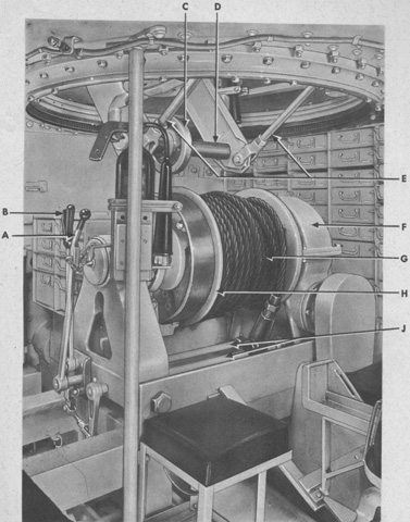
The winch assembly is seen installed under the turret. A portable fire extinguisher is mounted on the opposite side of the support post, and copious stowage drawers can be seen around the vehicle interior. A. Lever, assembly. B. Lever, assembly. C. Sheave, assembly. D. Shaft. E. Rod, assembly. F. Winch, assembly. G. Rope, assembly. H. Drum, assembly. J. Shaft. (Picture from ORD 7-8-9 SNL G-169 C2 Organizational Spare Parts and Equipment, Higher Echelon Spare Parts and Equipment (Addendum) Service Parts Catalog for Vehicle, Tank Recovery, M31 (T2) (Tank, Medium, M3, w/Crane).)
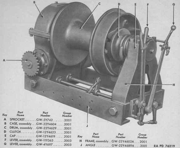
Radial-engined vehicles were equipped with the Gar Wood 22Y4695, shown here from the right rear. (Picture from ORD 7-8-9 SNL G-169 C2 Organizational Spare Parts and Equipment, Higher Echelon Spare Parts and Equipment (Addendum) Service Parts Catalog for Vehicle, Tank Recovery, M31 (T2) (Tank, Medium, M3, w/Crane).)
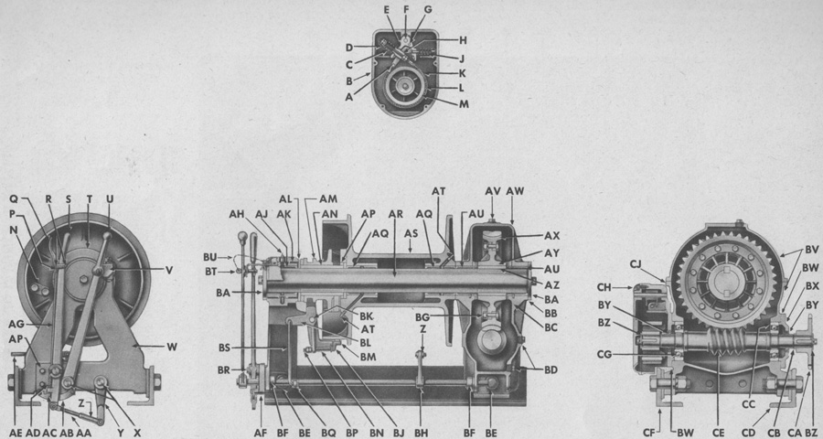
Diesel vehicles, on the other hand, used the Gar Wood 22Y4693. A. Link. B. Case, assembly (includes F). C. Spring. D. Washer. E. Rocker, assembly. F. Pin. G. Pin, assembly. H. Spacer. J. Spring. K. Band, assembly (includes L). L. Lining, w/rivets, assembly. M. Disk. N. Clamp; stud; nut. P. End. Q. Latch. R. Rivet. S. Lever, assembly (includes P, Q, R, AD, and AG). T. Cap. U. Lever, assembly. V. Bracket. W. Frame, assembly (includes T, AK, and BE). X. Shaft. Y. Lever, assembly. Z. Yoke, assembly. AA. Rod, assembly. AB. Segment; stud; nut; washer. AC. Pawl. AD. Spring; washer. AE. Rod, assembly. AF. Bracket; nut; screw; washer. AG. Rod, assembly (includes AC). AH. Fitting. AJ. Bushing. AK. Sleeve, assembly (includes AH and AJ). AL. Ring. AM. Clutch. AN. Key. AP. Ring. AQ. Bushing. AR. Shaft, assembly (includes AN and AZ). AS. Drum, assembly (includes N, AT, and AQ). AT. Fitting. AU. Bushing. AV. Plug. AW. Cover, assembly (includes AV). AX. Gear. AY. Spider, assembly (includes BG). AZ. Key. BA. Washer. BB. Shim. BC. Case, assembly (includes BD and BE). BD. Plug. BE. Bolt, assembly. BF. Collar, assembly. BG. Bolt; nut; washer. BH. Lever, assembly. BJ. Shoe, assembly (includes BM). BK. Pin, assembly. BL. Yoke, assembly (includes BN and BP). BM. Lining, w/rivets, assembly. BN. Spring. BP. Bolt; nut. BQ. Lever, assembly. BR. Shaft; rivet; washer; pin. BS. Link, assembly. BT. Pin, assembly. BU. Chain. BV. Case, assembly (includes AU, AW, BC, and CJ). BW. Gasket. BX. Cap. BY. Oil seal. BZ. Washer. CA. Sprocket. CB. Spacer. CC. Bearing. CD. Angle, assembly. CE. Worm, assembly. CF. Angle, assembly. CG. Bearing. CH. Cover. CJ. Gasket. (Picture from ORD 7-8-9 SNL G-169 C2 Organizational Spare Parts and Equipment, Higher Echelon Spare Parts and Equipment (Addendum) Service Parts Catalog for Vehicle, Tank Recovery, M31 (T2) (Tank, Medium, M3, w/Crane).)
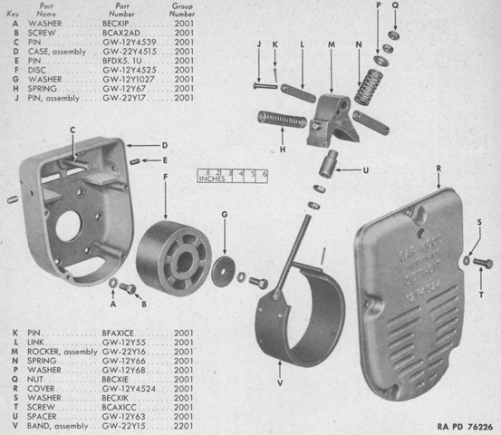
An exploded view of the winch's automatic brake and brake case assembly is diagrammed here. (Picture from ORD 7-8-9 SNL G-169 C2 Organizational Spare Parts and Equipment, Higher Echelon Spare Parts and Equipment (Addendum) Service Parts Catalog for Vehicle, Tank Recovery, M31 (T2) (Tank, Medium, M3, w/Crane).)
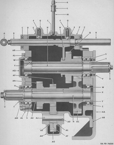
A sectional view of the power take-off for gasoline-engined vehicles is sketched. A. Eye; nut; washer; washer. B. Spacer. C. Oil seal. D. Tube. E. Ball. F. Spring. G. Poppet. H. Shaft, assembly. J. Plug. K. Vent. L. Coupling. M. Nipple. N. Yoke. P. Cover, assembly (includes J). Q. Gear. R. Rod, assembly (includes A). S. Bearing. T. Spacer. U. Washer; screw; washer. V. Oil seal. W. Bearing. X. Spacer. Y. Spacer. Z. Spacer. AA. Support. AB. Gasket. AC. Gear. AD. Pin. AE. Washer. AF. Bearing. AG. Gear. AH. Case, assembly. AJ. Rivet. AK. Spacer. AL. Gasket. AM. Cover. AN. Gear. AP. Gear. AQ. Cover. AR. Gasket. (Picture from ORD 7-8-9 SNL G-169 C2 Organizational Spare Parts and Equipment, Higher Echelon Spare Parts and Equipment (Addendum) Service Parts Catalog for Vehicle, Tank Recovery, M31 (T2) (Tank, Medium, M3, w/Crane).)
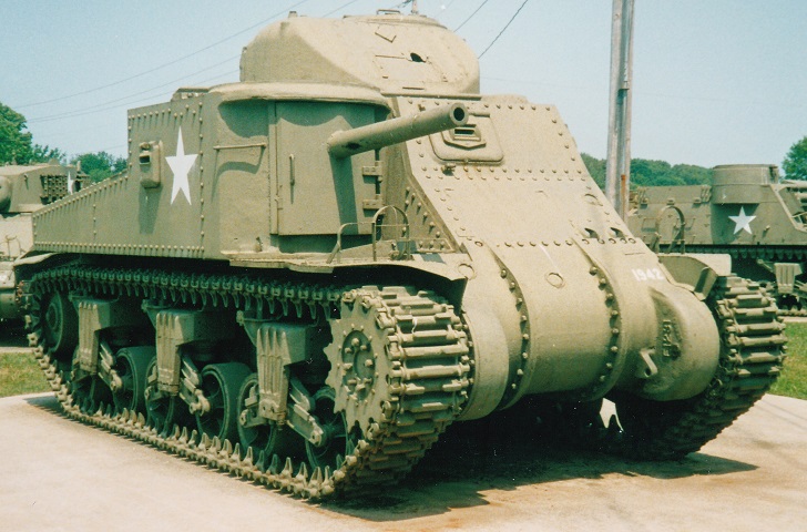
Although appearing much like a riveted medium tank M3, this is an M31B2 recovery vehicle. The dummy 75mm gun barrel is mounted on an access door, and the face of the turret would normally be occupied by the crane boom. The circular weld marks on the front hull show where pegs for stowing extra road wheels had been attached. This tank has both of the hull machine gun ports, but in US practice only the inboard machine gun would be mounted. The recovery vehicle variant lacks the characteristic M3 machine gun cupola, and this machine appears to be wearing T49 tracks.
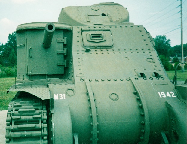
A closer look at the door and dummy 75mm gun is provided here. The weld marks for attachment of a grouser stowage box can be seen below the driver's port; further grouser boxes were mounted on the roof above the dummy 75mm gun and on the hull roof above the driver's port.
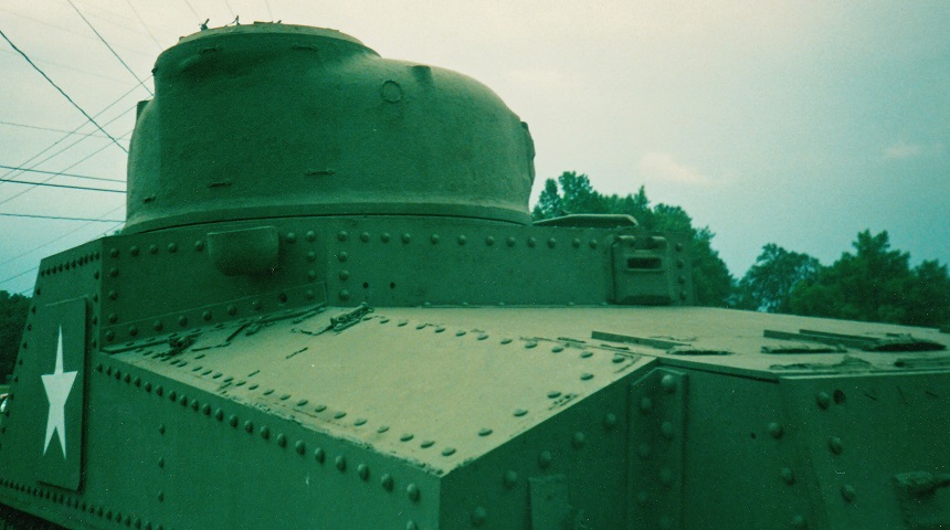
The circular weld mark on the rear of the turret indicates where the dummy 37mm gun was attached, and the turret would normally be reversed so the crane boom rested on the hull rear deck and also so this dummy gun was trained forward. Stowage boxes were mounted on the side sponsons, and the remnants of their attachment can be seen around the outside of the rivets.
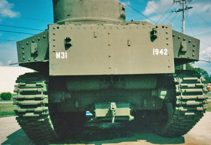
Although labeled as an M31, the engine exhaust and rear hull armor arrangement show that this vehicle was based on the M3A5, meaning that is actually an M31B2. A towing pintle has been added below the engine exhaust.
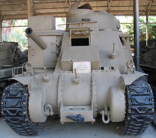
This vehicle is more complete, and allows us to see the towing pintle on the final drive and differential cover, the spare road wheel mountings, and the grouser boxes on the front hull and hull roof. A dummy 37mm gun is present as well. ("M31-ARV-batey-haosef-1.jpg" taken on 2 Oct 2005 by Bukvoed. Used under CC BY 2.5; cropped and resized from original.)
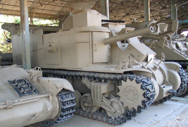
The rear stowage boxes are mounted, and the crane boom on the face of the turret is stowed to the rear of the vehicle. ("M31-ARV-batey-haosef-2.jpg" taken on 2 Oct 2005 by Bukvoed. Used under CC BY 2.5; cropped and resized from original.)
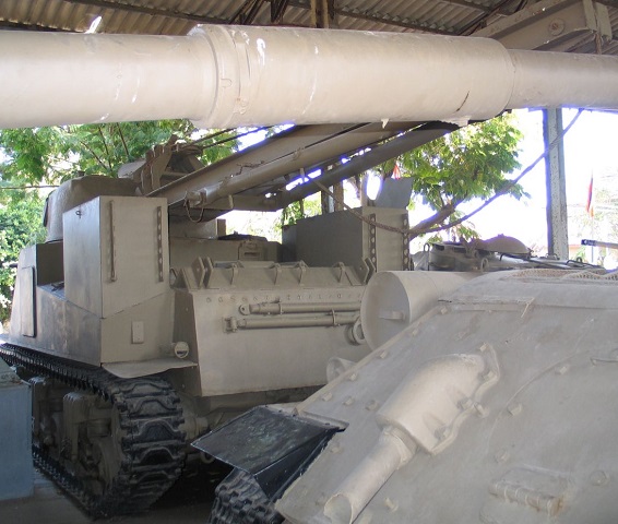
The rear armor and engine exhaust allow us to identify the base vehicle as an M3A3. Spare track blocks were stowed on the rear stowage boxes, and a better view of the crane boom and its support jacks is provided. ("M31-ARV-batey-haosef-3.jpg" taken on 2 Oct 2005 by Bukvoed. Used under CC BY 2.5; cropped and resized from original.)