


| M3 Grant I M3A1 M3A2 |
M3A5 M3A3 M3A4 |
| M3: General | |||
| Date of first acceptance | June 1941 | Total acceptances | 3,712 |
| Manufacturers |
|
Crew |
|
| M3: Dimensions | |||
| Combat weight with T48 or T51 tracks | 61,500lbs 27,900kg |
Height over cupola | 123" 312cm |
| Length without gun, without sandshields | 222" 564cm |
Gun overhang forward with 75mm gun M3 | 19" 48cm |
| Width over side doors | 107" 272cm |
Tread | 83" 211cm |
| Ground clearance | 17" 43cm |
Fire height, 75mm gun | 69" 175cm |
| Turret ring diameter | 54.5" 138cm |
Ground pressure, zero penetration | 12.6psi .885kg/cm² |
| M3: Armament | |||||
| Type | Mount | Ammunition | Traverse | Max traverse rate | Elevation |
| 75mm Gun M2 or M3 | M1 in hull right front | 50 rounds | 30° (15° left and right; manual) |
-- | +20° to -9° (manual) |
| 37mm Gun M5 or M6 | M24 in turret | 178 rounds | 360° (manual and hydraulic) |
18°/sec | +60° to -7° (manual) |
| .30cal M1919A4 MG | Cupola mount M26 on turret | 9,200 rounds | 360° (manual) |
-- | +60° to -8.5° (manual) |
| .30cal M1919A4 MG | Coaxial to 37mm gun | 360° (manual and hydraulic) |
18°/sec | +60° to -7° (manual) |
|
| Two .30cal M1919A4 MG | Fixed in bow mount M27 in hull left front | 0° | -- | +10° to -5° (manual) |
|
| Aiming equipment | |||||
| Periscope M2 with telescope M19 or M19A1 for 37mm gunner; periscope M1 with telescope M21 or M21A1 for 75mm gunner | |||||
| Stabilizer | |||||
| Elevation only (75mm and 37mm guns) | |||||
| M3: Armor | ||
| Assembly | ||
| Riveting | ||
| Hull | ||
| Rolled homogeneous steel | ||
| Location | Thickness | Angle from vertical |
| Upper front | 2.0" 5.1cm |
30° |
| Middle front | 1.5" 3.8cm |
53° |
| Lower front | 2.0" 5.1cm |
0° to 45° |
| Sides | 1.5" 3.8cm |
0° |
| Rear | 1.5" 3.8cm |
0° to 10° |
| Top | .50" 1.3cm |
83° to 90° |
| Front floor | 1.0" 2.5cm |
90° |
| Rear floor | .50" 1.3cm |
90° |
| Turret | ||
| Cast homogeneous steel | ||
| Location | Thickness | Angle from vertical |
| Front | 2.0" 5.1cm |
47° |
| Sides | 2.0" 5.1cm |
5° |
| Rear | 2.0" 5.1cm |
5° |
| Top | .875" 2.22cm |
90° |
| M3: Automotive | |||||
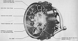
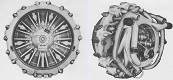
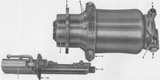
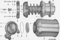
| Engine | Wright (Continental) R975 EC2; 9 cylinder, 4 cycle, static radial, supercharged gasoline | ||||
| Horsepower | Net: 340@2,400rpm Gross: 400@2,400rpm |
Torque | Net: 800 ft-lb@1,800rpm Gross: 890 ft-lb@1,800rpm |
Fuel capacity | 175gal 662L |
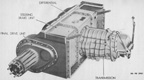
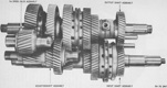
| Transmission | Synchromesh, 5 speeds forward, 1 reverse | ||||
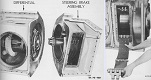
| Steering | Controlled differential, steering levers | ||||
| Brakes | Mechanical, external contracting | ||||
| M3: Suspension | ||
| Type | Road wheels | Track return rollers |
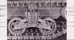
| Vertical volute spring | 3 bogies/track; 2 wheels/bogie |
1 on top of each bogie |
| Drive sprockets | Idlers | Shock absorbers | 13-tooth front drive | Adjustable at rear of track | None |
| M3: Track | |||||||
| T41 | |||||||
| Outside guide, double pin, smooth, rubber | |||||||
| Width | 16.0" 40.6cm |
Pitch | 6" 15cm |
Shoes/track | 79 | Ground contact length | 147" 373cm |
| T48 | |||||||
| Outside guide, double pin, chevron, rubber | |||||||
| Width | 16.56" 42.06cm |
Pitch | 6" 15cm |
Shoes/track | 79 | Ground contact length | 147" 373cm |
| T49 | |||||||
| Outside guide, double pin, parallel bar, steel | |||||||
| Width | 16.56" 42.06cm |
Pitch | 6" 15cm |
Shoes/track | 79 | Ground contact length | 147" 373cm |
| T51 | |||||||
| Outside guide, double pin, smooth, rubber | |||||||
| Width | 16.56" 42.06cm |
Pitch | 6" 15cm |
Shoes/track | 79 | Ground contact length | 147" 373cm |
| M3: Performance | |||
| Max level road speed | 21mph sustained 24mph dash 34kph sustained 39kph dash |
Max trench | 90" 230cm |
| Max grade | 60% | Max vertical obstacle | 24" 61cm |
| Min turning diameter | 62' 19m |
Max fording depth | 40" 100cm |
| Cruising range | ~120mi, roads ~190km, roads |
||
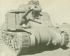
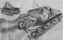
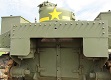
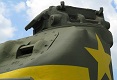
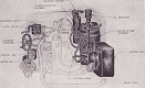
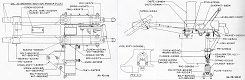
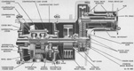
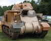
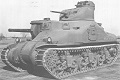
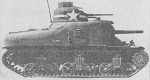
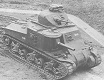
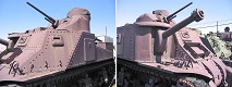
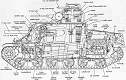
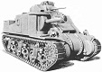
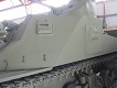
The medium tank M3 was based on the medium tank M2, utilizing its suspension, power train, and other mechanical parts. The M3 was called Lee I by the British, and the turret machine gun cupola was often replaced in British service with a flat rotating split hatch.
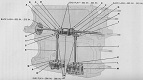
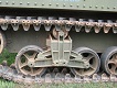
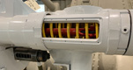
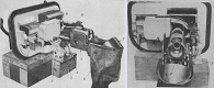
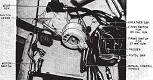
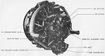
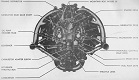
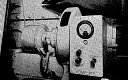
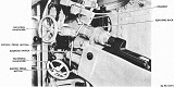
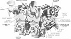
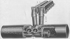
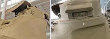
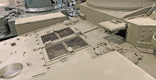
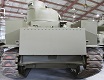
Late-production tanks had the doors originally on each hull side replaced by a floor escape hatch, but the right-side pistol port remained. Starting in March 1942, one of the driver's fixed machine guns was removed as well; the resulting hole was filled with a steel plug. The other bow machine gun omitted by June 1942. The crew of late M3s was reduced to six men when the driver also took over the role of radio operator. Very late production M3s had new heavy-duty suspension bogies with 8" (20cm) instead of 7" (18cm) volute springs, and the track return rollers were moved to the rear of the new bogies. Late vehicles also had a direct-sight telescope M15 installed to the left of the 75mm gun since it was difficult to maintain alignment with the original periscope M1, and another periscope was installed above the driver's position. High carbon monoxide levels in the fighting compartment led to the installation of two ventilators on the hull roof and a third on the turret roof. The engine intake and exhaust setup was shown to excessively heat the combustion air as well as produce undue exhaust backpressure. The engine air cleaners were therefore moved to the outside of the engine compartment, and the pepperpot exhausts were changed to fishtail exhausts with mufflers and modified exhaust collector rings with exits at the top of the engine. Before full production of the final redesign could be implemented, a quick-fix setup was used that included exterior air cleaners and straight exhausts with no mufflers.
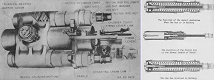
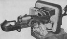
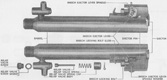
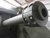
The armament of late-model tanks included the M3 75mm gun and M6 37mm gun. The differences in the 37mm and 75mm guns are as follows: The 37mm gun M5 was 6" (15cm) shorter than the M6, and the M5 had a manually-operated breechblock instead of the M6's semiautomatic breechblock. The 75mm gun M3 had a longer barrel than the M2.
Gun stabilizers were installed in tanks manufactured by the Detroit Tank Arsenal by November 1941, and expanded to the rest of the production lines starting in January 1942. Tanks with stabilization systems installed can be differentiated from those without by the presence of a cylindrical counterweight under the 37mm gun, and a counterweight at the end of the 75mm gun barrel if the tank is armed with the shorter 75mm gun M2. The longer 75mm gun M3 did not require a counterweight to be compatible with the gyrostabilizer.
| Grant I: General | |||
| Date of first acceptance | August 1941 | Total acceptances | 1,212 |
| Manufacturers |
|
Crew |
|
| Grant I: Dimensions | |||
| Combat weight with T51 tracks | 62,000lbs 28,100kg |
Height over turret periscope | 119" 302cm |
| Length without gun, without sandshields | 222" 564cm |
Gun overhang forward with 75mm gun M2 | 0" |
| Width over side doors | 107" 272cm |
Tread | 83" 211cm |
| Ground clearance | 17" 43cm |
Fire height, 75mm gun | 69" 175cm |
| Turret ring diameter | 54.5" 138cm |
Ground pressure, zero penetration | 12.7psi .892kg/cm² |
| Grant I: Armament | |||||
| Type | Mount | Ammunition | Traverse | Max traverse rate | Elevation |
| 75mm Gun M2 | M1 in hull right front | 65 rounds | 30° (15° left and right; manual) |
-- | +20° to -9° (manual) |
| 37mm Gun M5 or M6 | M24 in turret | 128 rounds | 360° (manual and hydraulic) |
18°/sec | +60° to -7° (manual) |
| .30cal M1919A4 MG | Coaxial to 37mm gun | 4,084 rounds | 360° (manual and hydraulic) |
18°/sec | +60° to -7° (manual) |
| Two .30cal M1919A4 MG | Fixed in bow mount M27 in hull left front | 0° | -- | +10° to -5° (manual) |
|
| Aiming equipment | |||||
| Periscope M2 with telescope M40 for 37mm gunner; periscope M1 with telescope M45 for 75mm gunner | |||||
| Stabilizer | |||||
| Elevation only (75mm and 37mm guns) | |||||
| Grant I: Armor | ||
| Assembly | ||
| Riveting | ||
| Hull | ||
| Rolled homogeneous steel | ||
| Location | Thickness | Angle from vertical |
| Upper front | 2.0" 5.1cm |
30° |
| Middle front | 1.5" 3.8cm |
53° |
| Lower front | 2.0" 5.1cm |
0° to 45° |
| Sides | 1.5" 3.8cm |
0° |
| Rear | 1.5" 3.8cm |
0° to 10° |
| Top | .50" 1.3cm |
83° to 90° |
| Front floor | 1.0" 2.5cm |
90° |
| Rear floor | .50" 1.3cm |
90° |
| Turret | ||
| Cast homogeneous steel | ||
| Location | Thickness | Angle from vertical |
| Front | 3.0" 7.6cm |
47° |
| Sides | 2.0" 5.1cm |
0° to 30° |
| Rear | 2.0" 5.1cm |
0° |
| Top | 1.25" 3.18cm |
80° to 90° |
| Grant I: Automotive | |||||
| Engine | Wright (Continental) R975 EC2; 9 cylinder, 4 cycle, static radial, supercharged gasoline | ||||
| Horsepower | Net: 340@2,400rpm Gross: 400@2,400rpm |
Torque | Net: 800 ft-lb@1,800rpm Gross: 890 ft-lb@1,800rpm |
Fuel capacity | 175gal 662L |
| Transmission | Synchromesh, 5 speeds forward, 1 reverse | ||||
| Steering | Controlled differential, steering levers | ||||
| Brakes | Mechanical, external contracting | ||||
| Grant I: Suspension | ||
| Type | Road wheels | Track return rollers |
| Vertical volute spring | 3 bogies/track; 2 wheels/bogie |
1 on top of each bogie |
| Drive sprockets | Idlers | Shock absorbers |
| 13-tooth front drive | Adjustable at rear of track | None |
| Grant I: Track | |||||||
| WE 210 | |||||||
| Outside guide, double pin, double I, rubber | |||||||
| Width | 16.0" 40.6cm |
Pitch | 6" 15cm |
Shoes/track | 79 | Ground contact length | 147" 373cm |
| T41 | |||||||
| Outside guide, double pin, smooth, rubber | |||||||
| Width | 16.0" 40.6cm |
Pitch | 6" 15cm |
Shoes/track | 79 | Ground contact length | 147" 373cm |
| T48 | |||||||
| Outside guide, double pin, chevron, rubber | |||||||
| Width | 16.56" 42.06cm |
Pitch | 6" 15cm |
Shoes/track | 79 | Ground contact length | 147" 373cm |
| T51 | |||||||
| Outside guide, double pin, smooth, rubber | |||||||
| Width | 16.56" 42.06cm |
Pitch | 6" 15cm |
Shoes/track | 79 | Ground contact length | 147" 373cm |
| Grant I: Performance | |||
| Max level road speed | 21mph sustained 24mph dash 34kph sustained 39kph dash |
Max trench | 90" 230cm |
| Max grade | 60% | Max vertical obstacle | 24" 61cm |
| Min turning diameter | 62' 19m |
Max fording depth | 40" 100cm |
| Cruising range | ~120mi, roads ~190km, roads |
||
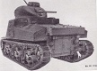
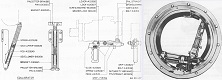
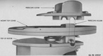
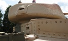
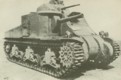
The British were not wholly satisfied with the design of the medium tank M3 and were permitted to make changes to the turret and fighting compartment. A new turret designed by Leslie Edward "Ted" Carr was used, and this featured a bulge at the rear for housing the radio, which was operated by the tank commander instead of a dedicated crewman. The turret machine gun cupola was also deleted, as its height was considered excessive on both the battlefield and the railroad: shipping tanks by train in England would require its removal. A 2" Mortar Mark I (smoke) was installed in the turret's front right corner. This was fixed in elevation, and 14 smoke rounds were carried. Initially, production of the mortars lagged, and a 1" (2.5cm) armor plug was therefore installed in its aperture in the turret casting. Ammunition stowage was modified after battle experience in North Africa to eighty 75mm and eighty 37mm rounds in British-designed armored stowage boxes.


| M3A1: General | |||
| Date of first acceptance | January 1942 | Total acceptances | 300 |
| Manufacturer | American Locomotive Co. | Crew |
|
| M3A1: Dimensions | |||
| Combat weight with T48 or T51 tracks | 63,000lbs 28,600kg |
Height over cupola | 123" 312cm |
| Length without gun, without sandshields | 222" 564cm |
Gun overhang forward with 75mm gun M3 | 19" 48cm |
| Width over side doors | 107" 272cm |
Tread | 83" 211cm |
| Ground clearance | 17" 43cm |
Fire height, 75mm gun | 69" 175cm |
| Turret ring diameter | 54.5" 138cm |
Ground pressure, zero penetration | 12.9psi .906kg/cm² |
| M3A1: Armament | |||||
| Type | Mount | Ammunition | Traverse | Max traverse rate | Elevation |
| 75mm Gun M2 or M3 | M1 in hull right front | 50 rounds | 30° (15° left and right; manual) |
-- | +20° to -9° (manual) |
| 37mm Gun M5 or M6 | M24 in turret | 178 rounds | 360° (manual and hydraulic) |
18°/sec | +60° to -7° (manual) |
| .30cal M1919A4 MG | Cupola mount M26 on turret | 9,200 rounds | 360° (manual) |
-- | +60° to -8.5° (manual) |
| .30cal M1919A4 MG | Coaxial to 37mm gun | 360° (manual and hydraulic) |
18°/sec | +60° to -7° (manual) |
|
| Two .30cal M1919A4 MG | Fixed in bow mount M27 in hull left front | 0° | -- | +10° to -5° (manual) |
|
| Aiming equipment | |||||
| Periscope M2 with telescope M19 or M19A1 for 37mm gunner; periscope M1 with telescope M21 or M21A1 for 75mm gunner | |||||
| Stabilizer | |||||
| Elevation only (75mm and 37mm guns) | |||||
| M3A1: Armor | ||
| Assembly | ||
| Riveting | ||
| Hull | ||
| Upper cast, lower rolled homogeneous steel | ||
| Location | Thickness | Angle from vertical |
| Upper front | 2.0" 5.1cm |
30° |
| Middle front | 1.5" 3.8cm |
53° |
| Lower front | 2.0" 5.1cm |
0° to 45° |
| Sides | 1.5" 3.8cm |
0° |
| Rear | 1.5" 3.8cm |
0° to 10° |
| Top | .50" 1.3cm |
83° to 90° |
| Front floor | 1.0" 2.5cm |
90° |
| Rear floor | .50" 1.3cm |
90° |
| Turret | ||
| Cast homogeneous steel | ||
| Location | Thickness | Angle from vertical |
| Front | 2.0" 5.1cm |
47° |
| Sides | 2.0" 5.1cm |
5° |
| Rear | 2.0" 5.1cm |
5° |
| Top | .875" 2.22cm |
90° |
| M3A1: Automotive | |||||
| Engine | Wright (Continental) R975 EC2; 9 cylinder, 4 cycle, static radial, supercharged gasoline | ||||
| Horsepower | Net: 340@2,400rpm Gross: 400@2,400rpm |
Torque | Net: 800 ft-lb@1,800rpm Gross: 890 ft-lb@1,800rpm |
Fuel capacity | 175gal 662L |
| Transmission | Synchromesh, 5 speeds forward, 1 reverse | ||||
| Steering | Controlled differential, steering levers | ||||
| Brakes | Mechanical, external contracting | ||||
| M3A1: Suspension | ||
| Type | Road wheels | Track return rollers |
| Vertical volute spring | 3 bogies/track; 2 wheels/bogie |
1 on top of each bogie |
| Drive sprockets | Idlers | Shock absorbers | 13-tooth front drive | Adjustable at rear of track | None |
| M3A1: Track | |||||||
| T41 | |||||||
| Outside guide, double pin, smooth, rubber | |||||||
| Width | 16.0" 40.6cm |
Pitch | 6" 15cm |
Shoes/track | 79 | Ground contact length | 147" 373cm |
| T48 | |||||||
| Outside guide, double pin, chevron, rubber | |||||||
| Width | 16.56" 42.06cm |
Pitch | 6" 15cm |
Shoes/track | 79 | Ground contact length | 147" 373cm |
| T49 | |||||||
| Outside guide, double pin, parallel bar, steel | |||||||
| Width | 16.56" 42.06cm |
Pitch | 6" 15cm |
Shoes/track | 79 | Ground contact length | 147" 373cm |
| T51 | |||||||
| Outside guide, double pin, smooth, rubber | |||||||
| Width | 16.56" 42.06cm |
Pitch | 6" 15cm |
Shoes/track | 79 | Ground contact length | 147" 373cm |
| M3A1: Performance | |||
| Max level road speed | 21mph sustained 24mph dash 34kph sustained 39kph dash |
Max trench | 90" 230cm |
| Max grade | 60% | Max vertical obstacle | 24" 61cm |
| Min turning diameter | 62' 19m |
Max fording depth | 40" 100cm |
| Cruising range | ~120mi, roads ~190km, roads |
||
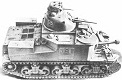
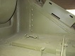
Except for the cast upper hull, the M3A1 was largely identical to the M3. The door in the right side hull roof was placed on the rear slope of the 75mm gun sponson. This hatch was hinged from the front on early vehicles, and opened to the rear on later models. Cast hulls eliminated the need for bolts and rivets, which increased crew safety as well as decreased hull manufacturing and machining time (though a cast hull required about two weeks for the hardening and cooling processes, assembly of the cast hull required 100 man-hours compared to 1,100 man-hours for a riveted hull). Other benefits included the increased chance of ricochets due to its rounded shape, and also cheaper production which saved ~$3,000 per hull produced. The British referred to M3A1 as Lee II. The Guiberson T-1400-2 9-cylinder, 4 cycle, diesel radial engine was going to be used in M3A1s built by the American Locomotive Company, and these were designated as M3A1(diesel). This engine's low-end torque offered improved performance, and it increased fuel mileage over the gasoline radial. It proved unreliable in tests, however, and production plans were scuttled after 28 M3A1(diesel)s were manufactured.


| M3A2: General | |||
| Date of first acceptance | January 1942 | Total acceptances | 12 |
| Manufacturers |
|
Crew |
|
| M3A2: Dimensions | |||
| Combat weight with T48 or T51 tracks | 60,400lbs 27,400kg |
Height over cupola | 123" 312cm |
| Length without gun, without sandshields | 222" 564cm |
Gun overhang forward with 75mm gun M3 | 19" 48cm |
| Width over side doors | 107" 272cm |
Tread | 83" 211cm |
| Ground clearance | 17" 43cm |
Fire height, 75mm gun | 69" 175cm |
| Turret ring diameter | 54.5" 138cm |
Ground pressure, zero penetration | 12.4psi .870kg/cm² |
| M3A2: Armament | |||||
| Type | Mount | Ammunition | Traverse | Max traverse rate | Elevation |
| 75mm Gun M2 or M3 | M1 in hull right front | 50 rounds | 30° (15° left and right; manual) |
-- | +20° to -9° (manual) |
| 37mm Gun M5 or M6 | M24 in turret | 178 rounds | 360° (manual and hydraulic) |
18°/sec | +60° to -7° (manual) |
| .30cal M1919A4 MG | Cupola mount M26 on turret | 9,200 rounds | 360° (manual) |
-- | +60° to -8.5° (manual) |
| .30cal M1919A4 MG | Coaxial to 37mm gun | 360° (manual and hydraulic) |
18°/sec | +60° to -7° (manual) |
|
| Two .30cal M1919A4 MG | Fixed in bow mount M27 in hull left front | 0° | -- | +10° to -5° (manual) |
|
| Aiming equipment | |||||
| Periscope M2 with telescope M19 or M19A1 for 37mm gunner; periscope M1 with telescope M21 or M21A1 for 75mm gunner | |||||
| Stabilizer | |||||
| Elevation only (75mm and 37mm guns) | |||||
| M3A2: Armor | ||
| Assembly | ||
| Welding | ||
| Hull | ||
| Rolled homogeneous steel | ||
| Location | Thickness | Angle from vertical |
| Upper front | 2.0" 5.1cm |
30° |
| Middle front | 1.5" 3.8cm |
53° |
| Lower front | 2.0" 5.1cm |
0° to 45° |
| Sides | 1.5" 3.8cm |
0° |
| Rear | 1.5" 3.8cm |
0° to 10° |
| Top | .50" 1.3cm |
83° to 90° |
| Front floor | 1.0" 2.5cm |
90° |
| Rear floor | .50" 1.3cm |
90° |
| Turret | ||
| Cast homogeneous steel | ||
| Location | Thickness | Angle from vertical |
| Front | 2.0" 5.1cm |
47° |
| Sides | 2.0" 5.1cm |
5° |
| Rear | 2.0" 5.1cm |
5° |
| Top | .875" 2.22cm |
90° |
| M3A2: Automotive | |||||
| Engine | Wright (Continental) R975 EC2; 9 cylinder, 4 cycle, static radial, supercharged gasoline | ||||
| Horsepower | Net: 340@2,400rpm Gross: 400@2,400rpm |
Torque | Net: 800 ft-lb@1,800rpm Gross: 890 ft-lb@1,800rpm |
Fuel capacity | 175gal 662L |
| Transmission | Synchromesh, 5 speeds forward, 1 reverse | ||||
| Steering | Controlled differential, steering levers | ||||
| Brakes | Mechanical, external contracting | ||||
| M3A2: Suspension | ||
| Type | Road wheels | Track return rollers |
| Vertical volute spring | 3 bogies/track; 2 wheels/bogie |
1 on top of each bogie |
| Drive sprockets | Idlers | Shock absorbers | 13-tooth front drive | Adjustable at rear of track | None |
| M3A2: Track | |||||||
| T41 | |||||||
| Outside guide, double pin, smooth, rubber | |||||||
| Width | 16.0" 40.6cm |
Pitch | 6" 15cm |
Shoes/track | 79 | Ground contact length | 147" 373cm |
| T48 | |||||||
| Outside guide, double pin, chevron, rubber | |||||||
| Width | 16.56" 42.06cm |
Pitch | 6" 15cm |
Shoes/track | 79 | Ground contact length | 147" 373cm |
| T49 | |||||||
| Outside guide, double pin, parallel bar, steel | |||||||
| Width | 16.56" 42.06cm |
Pitch | 6" 15cm |
Shoes/track | 79 | Ground contact length | 147" 373cm |
| T51 | |||||||
| Outside guide, double pin, smooth, rubber | |||||||
| Width | 16.56" 42.06cm |
Pitch | 6" 15cm |
Shoes/track | 79 | Ground contact length | 147" 373cm |
| M3A2: Performance | |||
| Max level road speed | 21mph sustained 24mph dash 34kph sustained 39kph dash |
Max trench | 90" 230cm |
| Max grade | 60% | Max vertical obstacle | 24" 61cm |
| Min turning diameter | 62' 19m |
Max fording depth | 40" 100cm |
| Cruising range | ~120mi, roads ~190km, roads |
||
The M3A2 was identical to the M3 except for the M3A2's welded hull. Welding the hull saved weight for a given ballistic protection level; removed rivet heads and angles on the tank interior, which increased crew safety; and shortened the time and cost of assembly. The British designation for M3A2 was Lee III.
| M3A5: General | |||
| Date of first acceptance | January 1942 | Total acceptances | 591 |
| Manufacturer | Baldwin Locomotive Works | Crew |
|
| M3A5: Dimensions | |||
| Combat weight with T48 or T51 tracks | 64,000lbs 29,000kg |
Height over cupola | 123" 312cm |
| Length without gun, without sandshields | 222" 564cm |
Gun overhang forward with 75mm gun M3 | 19" 48cm |
| Width over side doors | 107" 272cm |
Tread | 83" 211cm |
| Ground clearance | 17" 43cm |
Fire height, 75mm gun | 69" 175cm |
| Turret ring diameter | 54.5" 138cm |
Ground pressure, zero penetration | 13.1psi .920kg/cm² |
| M3A5: Armament | |||||
| Type | Mount | Ammunition | Traverse | Max traverse rate | Elevation |
| 75mm Gun M2 or M3 | M1 in hull right front | 50 rounds | 30° (15° left and right; manual) |
-- | +20° to -9° (manual) |
| 37mm Gun M5 or M6 | M24 in turret | 178 rounds | 360° (manual and hydraulic) |
18°/sec | +60° to -7° (manual) |
| .30cal M1919A4 MG | Cupola mount M26 on turret | 9,200 rounds | 360° (manual) |
-- | +60° to -8.5° (manual) |
| .30cal M1919A4 MG | Coaxial to 37mm gun | 360° (manual and hydraulic) |
18°/sec | +60° to -7° (manual) |
|
| Two .30cal M1919A4 MG | Fixed in bow mount M27 in hull left front | 0° | -- | +10° to -5° (manual) |
|
| Aiming equipment | |||||
| Periscope M2 with telescope M19 or M19A1 for 37mm gunner; periscope M1 with telescope M21 or M21A1 for 75mm gunner | |||||
| Stabilizer | |||||
| Elevation only (75mm and 37mm guns) | |||||
| M3A5: Armor | ||
| Assembly | ||
| Riveting | ||
| Hull | ||
| Rolled homogeneous steel | ||
| Location | Thickness | Angle from vertical |
| Upper front | 2.0" 5.1cm |
30° |
| Middle front | 1.5" 3.8cm |
53° |
| Lower front | 2.0" 5.1cm |
0° to 45° |
| Sides | 1.5" 3.8cm |
0° |
| Rear | 1.5" 3.8cm |
0° to 10° |
| Top | .50" 1.3cm |
83° to 90° |
| Front floor | 1.0" 2.5cm |
90° |
| Rear floor | .50" 1.3cm |
90° |
| Turret | ||
| Cast homogeneous steel | ||
| Location | Thickness | Angle from vertical |
| Front | 2.0" 5.1cm |
47° |
| Sides | 2.0" 5.1cm |
5° |
| Rear | 2.0" 5.1cm |
5° |
| Top | .875" 2.22cm |
90° |
| M3A5: Automotive | |||||
| Engine | General Motors 6046; 12 cylinder (6/engine), 2 cycle, twin in-line diesel | ||||
| Horsepower | Net: 375@2,100 crankshaft rpm Gross: 410@2,900 propeller shaft rpm |
Torque | Net: 1,000 ft-lb@1,400 crankshaft rpm Gross: 885 ft-lb@1,900 propeller shaft rpm |
Fuel capacity | 150gal 570L |
| Transmission | Synchromesh, 5 speeds forward, 1 reverse | ||||
| Steering | Controlled differential, steering levers | ||||
| Brakes | Mechanical, external contracting | ||||
| M3A5: Suspension | ||
| Type | Road wheels | Track return rollers |
| Vertical volute spring | 3 bogies/track; 2 wheels/bogie |
1 on top of each bogie |
| Drive sprockets | Idlers | Shock absorbers | 13-tooth front drive | Adjustable at rear of track | None |
| M3A5: Track | |||||||
| T41 | |||||||
| Outside guide, double pin, smooth, rubber | |||||||
| Width | 16.0" 40.6cm |
Pitch | 6" 15cm |
Shoes/track | 79 | Ground contact length | 147" 373cm |
| T48 | |||||||
| Outside guide, double pin, chevron, rubber | |||||||
| Width | 16.56" 42.06cm |
Pitch | 6" 15cm |
Shoes/track | 79 | Ground contact length | 147" 373cm |
| T49 | |||||||
| Outside guide, double pin, parallel bar, steel | |||||||
| Width | 16.56" 42.06cm |
Pitch | 6" 15cm |
Shoes/track | 79 | Ground contact length | 147" 373cm |
| T51 | |||||||
| Outside guide, double pin, smooth, rubber | |||||||
| Width | 16.56" 42.06cm |
Pitch | 6" 15cm |
Shoes/track | 79 | Ground contact length | 147" 373cm |
| M3A5: Performance | |||
| Max level road speed | 25mph sustained 30mph dash 40kph sustained 48kph dash |
Max trench | 90" 230cm |
| Max grade | 60% | Max vertical obstacle | 24" 61cm |
| Min turning diameter | 62' 19m |
Max fording depth | 40" 100cm |
| Cruising range | ~150mi, roads ~240km, roads |
||
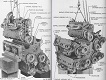
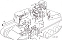
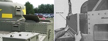
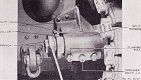
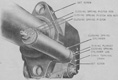
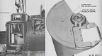
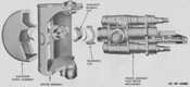
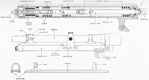
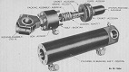
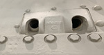
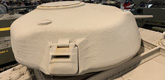
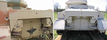
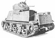
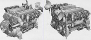
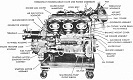
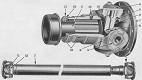
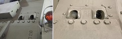
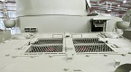
The radial gasoline engines of previous medium tanks M3 were also needed for training aircraft, and an engine shortage was foreseen. To help with the situation, the General Motors 6046 diesel engine was created. This was a pair of GM 6-71 truck engines, each of which could be operated independently if so required. The engines were meshed together via a power transfer unit using a helical gear mounted on a propeller shaft connecting to the tank's transmission. The side and rear armor plates on diesel-engined M3s extended below the level of the track return run, and the rear hull plate was sloped to accommodate the larger diesel engine. Instead of the twin engine access doors found on radial-engined M3s, the lower rear hull was a single plate. An exhaust deflector was installed to reduce the dust signature of the tank, and two armored doors with air intake louvres were installed over the tank's engine compartment. During production, the gear ratio in the power transfer unit was changed from 1:1.19 to 1:1.37, increasing the top speed from 25mph (40kph) to 29mph (47kph) at 2,100 engine rpm. When using a single engine, the top level road speed was 22mph (35kph) with the 1.19 ratio and ~20mph (~32kph) with the 1.37 ratio. The M3A5 was borne out of the dire shortage of tanks which necessitated the installation of the diesel engine in riveted-hull tanks as well as welded-hull vehicles. M3A5 was referred to by the British as Grant II.


| M3A3: General | |||
| Date of first acceptance | March 1942 | Total acceptances | 322 |
| Manufacturer | Baldwin Locomotive Works | Crew |
|
| M3A3: Dimensions | |||
| Combat weight with T48 or T51 tracks | 63,000lbs 28,600kg |
Height over cupola | 123" 312cm |
| Length without gun, without sandshields | 222" 564cm |
Gun overhang forward with 75mm gun M3 | 19" 48cm |
| Width over side doors | 107" 272cm |
Tread | 83" 211cm |
| Ground clearance | 17" 43cm |
Fire height, 75mm gun | 69" 175cm |
| Turret ring diameter | 54.5" 138cm |
Ground pressure, zero penetration | 12.9psi .906kg/cm² |
| M3A3: Armament | |||||
| Type | Mount | Ammunition | Traverse | Max traverse rate | Elevation |
| 75mm Gun M2 or M3 | M1 in hull right front | 50 rounds | 30° (15° left and right; manual) |
-- | +20° to -9° (manual) |
| 37mm Gun M5 or M6 | M24 in turret | 178 rounds | 360° (manual and hydraulic) |
18°/sec | +60° to -7° (manual) |
| .30cal M1919A4 MG | Cupola mount M26 on turret | 9,200 rounds | 360° (manual) |
-- | +60° to -8.5° (manual) |
| .30cal M1919A4 MG | Coaxial to 37mm gun | 360° (manual and hydraulic) |
18°/sec | +60° to -7° (manual) |
|
| Two .30cal M1919A4 MG | Fixed in bow mount M27 in hull left front | 0° | -- | +10° to -5° (manual) |
|
| Aiming equipment | |||||
| Periscope M2 with telescope M19 or M19A1 for 37mm gunner; periscope M1 with telescope M21 or M21A1 for 75mm gunner | |||||
| Stabilizer | |||||
| Elevation only (75mm and 37mm guns) | |||||
| M3A3: Armor | ||
| Assembly | ||
| Welding | ||
| Hull | ||
| Rolled homogeneous steel | ||
| Location | Thickness | Angle from vertical |
| Upper front | 2.0" 5.1cm |
30° |
| Middle front | 1.5" 3.8cm |
53° |
| Lower front | 2.0" 5.1cm |
0° to 45° |
| Sides | 1.5" 3.8cm |
0° |
| Rear | 1.5" 3.8cm |
0° to 10° |
| Top | .50" 1.3cm |
83° to 90° |
| Front floor | 1.0" 2.5cm |
90° |
| Rear floor | .50" 1.3cm |
90° |
| Turret | ||
| Cast homogeneous steel | ||
| Location | Thickness | Angle from vertical |
| Front | 2.0" 5.1cm |
47° |
| Sides | 2.0" 5.1cm |
5° |
| Rear | 2.0" 5.1cm |
5° |
| Top | .875" 2.22cm |
90° |
| M3A3: Automotive | |||||
| Engine | General Motors 6046; 12 cylinder (6/engine), 2 cycle, twin in-line diesel | ||||
| Horsepower | Net: 375@2,100 crankshaft rpm Gross: 410@2,900 propeller shaft rpm |
Torque | Net: 1,000 ft-lb@1,400 crankshaft rpm Gross: 885 ft-lb@1,900 propeller shaft rpm |
Fuel capacity | 150gal 570L |
| Transmission | Synchromesh, 5 speeds forward, 1 reverse | ||||
| Steering | Controlled differential, steering levers | ||||
| Brakes | Mechanical, external contracting | ||||
| M3A3: Suspension | ||
| Type | Road wheels | Track return rollers |
| Vertical volute spring | 3 bogies/track; 2 wheels/bogie |
1 on top of each bogie |
| Drive sprockets | Idlers | Shock absorbers | 13-tooth front drive | Adjustable at rear of track | None |
| M3A3: Track | |||||||
| T41 | |||||||
| Outside guide, double pin, smooth, rubber | |||||||
| Width | 16.0" 40.6cm |
Pitch | 6" 15cm |
Shoes/track | 79 | Ground contact length | 147" 373cm |
| T48 | |||||||
| Outside guide, double pin, chevron, rubber | |||||||
| Width | 16.56" 42.06cm |
Pitch | 6" 15cm |
Shoes/track | 79 | Ground contact length | 147" 373cm |
| T49 | |||||||
| Outside guide, double pin, parallel bar, steel | |||||||
| Width | 16.56" 42.06cm |
Pitch | 6" 15cm |
Shoes/track | 79 | Ground contact length | 147" 373cm |
| T51 | |||||||
| Outside guide, double pin, smooth, rubber | |||||||
| Width | 16.56" 42.06cm |
Pitch | 6" 15cm |
Shoes/track | 79 | Ground contact length | 147" 373cm |
| M3A3: Performance | |||
| Max level road speed | 25mph sustained 30mph dash 40kph sustained 48kph dash |
Max trench | 90" 230cm |
| Max grade | 60% | Max vertical obstacle | 24" 61cm |
| Min turning diameter | 62' 19m |
Max fording depth | 36" 91cm |
| Cruising range | ~150mi, roads ~240km, roads |
||
The M3A3 was a welded-hull Lee with the GM 6046 diesel engine; improvements to the power unit listed for the M3A5 appeared on the M3A3 as well. The British called diesel-engined M3A3s Lee V and Continental-engined M3A3s Lee IV. This may only be a paper designation, as no M3A3s were produced with the Continental R975. The British, trying to keep pace with the plethora of tank types emerging from the US, reserved designations for expected production models. Lee IV is apparently just such a designation that was reserved but whose vehicle never saw production.
| M3A4: General | |||
| Date of first acceptance | June 1942 | Total acceptances | 109 |
| Manufacturer | Detroit Tank Arsenal | Crew |
|
| M3A4: Dimensions | |||
| Combat weight with T48 or T51 tracks | 64,000lbs 29,000kg |
Height over cupola | 123" 312cm |
| Length without gun, without sandshields | 242" 615cm |
Gun overhang forward with 75mm gun M3 | 19" 48cm |
| Width without side doors | 104" 264cm |
Tread | 83" 211cm |
| Ground clearance | 16" 41cm |
Fire height, 75mm gun | 69" 175cm |
| Turret ring diameter | 54.5" 138cm |
Ground pressure, zero penetration | 12.1psi .849kg/cm² |
| M3A4: Armament | |||||
| Type | Mount | Ammunition | Traverse | Max traverse rate | Elevation |
| 75mm Gun M2 or M3 | M1 in hull right front | 50 rounds | 30° (15° left and right; manual) |
-- | +20° to -9° (manual) |
| 37mm Gun M5 or M6 | M24 in turret | 178 rounds | 360° (manual and hydraulic) |
18°/sec | +60° to -7° (manual) |
| .30cal M1919A4 MG | Cupola mount M26 on turret | 9,200 rounds | 360° (manual) |
-- | +60° to -8.5° (manual) |
| .30cal M1919A4 MG | Coaxial to 37mm gun | 360° (manual and hydraulic) |
18°/sec | +60° to -7° (manual) |
|
| Two .30cal M1919A4 MG | Fixed in hull left front | 0° | -- | Manual | |
| Aiming equipment | |||||
| Periscope M2 with telescope M19 or M19A1 for 37mm gunner; periscope M1 with telescope M21 or M21A1 for 75mm gunner | |||||
| Stabilizer | |||||
| Elevation only (75mm and 37mm guns) | |||||
| M3A4: Armor | ||
| Assembly | ||
| Riveting | ||
| Hull | ||
| Rolled homogeneous steel | ||
| Location | Thickness | Angle from vertical |
| Upper front | 2.0" 5.1cm |
30° |
| Middle front | 1.5" 3.8cm |
53° |
| Lower front | 2.0" 5.1cm |
0° to 45° |
| Sides | 1.5" 3.8cm |
0° |
| Rear | 1.5" 3.8cm |
0° to 20° |
| Top | .50" 1.3cm |
83° to 90° |
| Front floor | 1.0" 2.5cm |
90° |
| Rear floor | .50" 1.3cm |
90° |
| Turret | ||
| Cast homogeneous steel | ||
| Location | Thickness | Angle from vertical |
| Front | 2.0" 5.1cm |
47° |
| Sides | 2.0" 5.1cm |
5° |
| Rear | 2.0" 5.1cm |
5° |
| Top | .875" 2.22cm |
90° |
| M3A4: Automotive | |||||
| Engine | Chrysler A57; 30 cylinder, 4 cycle, multibank gasoline | ||||
| Horsepower | Net: 370@2,400 propeller shaft rpm Gross: 425@2,850 crankshaft rpm |
Torque | Net: 1,020 ft-lb@1,200 propeller shaft rpm Gross: 1,060 ft-lb@1,400 crankshaft rpm |
Fuel capacity | 160gal 660L |
| Transmission | Synchromesh, 5 speeds forward, 1 reverse | ||||
| Steering | Controlled differential, steering levers | ||||
| Brakes | Mechanical, external contracting | ||||
| M3A4: Suspension | ||
| Type | Road wheels | Track return rollers |
| Vertical volute spring | 3 bogies/track; 2 wheels/bogie |
1 on top of each bogie |
| Drive sprockets | Idlers | Shock absorbers | 13-tooth front drive | Adjustable at rear of track | None |
| M3A4: Track | |||||||
| T41 | |||||||
| Outside guide, double pin, smooth, rubber | |||||||
| Width | 16.0" 40.6cm |
Pitch | 6" 15cm |
Shoes/track | 83 | Ground contact length | 160" 406cm |
| T48 | |||||||
| Outside guide, double pin, chevron, rubber | |||||||
| Width | 16.56" 42.06cm |
Pitch | 6" 15cm |
Shoes/track | 83 | Ground contact length | 160" 406cm |
| T49 | |||||||
| Outside guide, double pin, parallel bar, steel | |||||||
| Width | 16.56" 42.06cm |
Pitch | 6" 15cm |
Shoes/track | 83 | Ground contact length | 160" 406cm |
| T51 | |||||||
| Outside guide, double pin, smooth, rubber | |||||||
| Width | 16.56" 42.06cm |
Pitch | 6" 15cm |
Shoes/track | 83 | Ground contact length | 160" 406cm |
| M3A4: Performance | |||
| Max level road speed | 20mph sustained 25mph dash 32kph sustained 40kph dash |
Max trench | 96" 240cm |
| Max grade | 60% | Max vertical obstacle | 24" 61cm |
| Min turning diameter | 70' 21m |
Max fording depth | 40" 100cm |
| Cruising range | ~100mi, roads ~160km, roads |
||
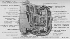
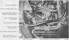
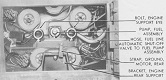
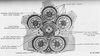
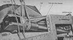
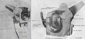
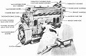
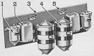
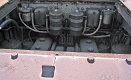
The M3A4's A57 power unit was composed of five Chrysler L-head automobile engines geared to run as a single motor, and was devised to help alleviate the expected shortage of tank engines. Each individual engine had its own crankshaft, pistons, camshaft, valves, manifold, carburetor, and distributor. All five engines were assembled to a common crankcase, inside of which each of the five engine crankshafts spun a drive gear which drove a larger gear that was keyed to the power unit driven gear shaft. This shaft drove the engine clutch. The size of this conglomeration required extending the hull of the M3A4, resulting in a distinctive space between the suspension bogies of M3A4s which is about 6" (15cm) longer than that of other M3s. Bulges in the engine compartment floor and roof accommodated the A57's fan and radiator, respectively. No production M3A4s featured side doors on the hull, and other late features like the stronger suspension bogies and three roof ventilators were present. M3A4 was called Lee VI by the British.