
12-ton Tractor Truck M26.
The armored covers for the windshield, radiator, and cab windows are open on this truck. All the armored covers could be operated from inside the cab, and all featured peep ports to allow protected vision. Copious tool stowage was provided, and the .50cal machine gun is stowed and covered. (Picture from TM 9-767 40-ton Tank Transporter Truck-Trailer M25.)

Although its winches and tools made the M26 capable of recovery operations by itself, it used a fifth wheel to be coupled to the semitrailer M15 to transport disabled tanks. The tandem rear winch assembly is visible behind the cab, and the machine gun cover has been removed on this example. A. Flares. B. Rear upper winch. C. Rear lower winch. D. Exhaust stack and shield. E. Jib crane socket. F. Vertical lifting device. G. Drive chain. H. Drive chain oiling system. J. Stabilizer coil springs. K. Shackle for towing. L. Pintle. M. Brake cylinder. N. Fifth wheel assembly. P. Whiffletree. Q. Floodlight. R. Rear windows. S. Gun, machine, .50 cal., M2. (Picture from TM 9-767 40-ton Tank Transporter Truck-Trailer M25.)
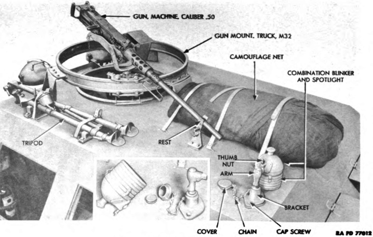
The cab roof, stowage, and machine gun ring mount are shown in this image. (Picture from TM 9-767 40-ton Tank Transporter Truck-Trailer M25.)

The contents of the left-side tool box and stowage on the left side of the cab are laid out in this image. (Picture from TM 9-767 40-ton Tank Transporter Truck-Trailer M25.)
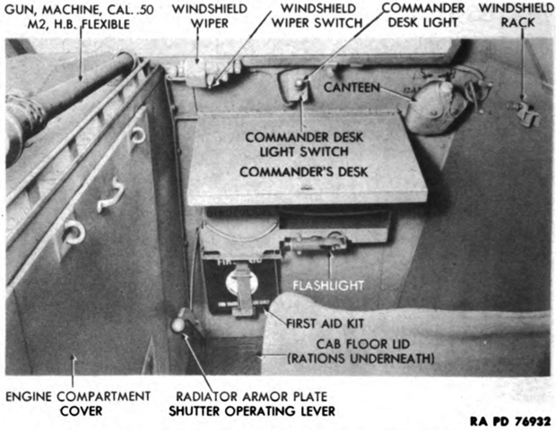
The vehicle commander was provided with a desk at his position at the right front of the cab. (Picture from TM 9-767 40-ton Tank Transporter Truck-Trailer M25.)

A combination blinker and spotlight was mounted at the right front corner of the cab roof, with the control handle above the commander's seat as seen on the left. It featured a removable hood on the front end, and the light could be taken from the roof and attached to a signal switch assembly with a wire reel for handheld use, illustrated on the right. (Picture from TM 9-767 40-ton Tank Transporter Truck-Trailer M25.)
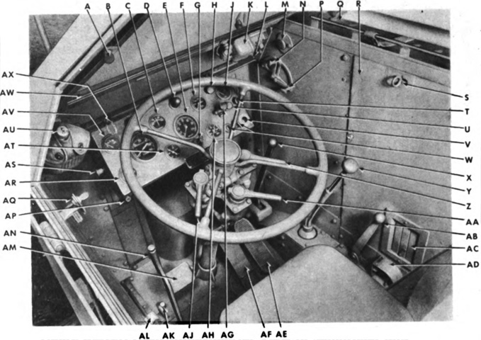
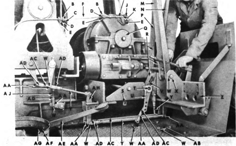
The driver's position is labeled here. A. Windshield thumb screw. B. Speedometer. C. Ammeter. D. Instrument panel light. E. Tachometer. F. Oil temperature gage. G. Tachometer telltale lock. H. Floodlight switch. J. Fuel gage (right fuel tank). K. Windshield wiper. L. Windshield wiper switch. M. Air horn button. N. Hand throttle lever. P. Choke lever. Q. Radiator filler cap cover. R. Engine compartment side cover (door). S. Turnbuckle. T. Siren light switch. U. Blackout driving light switch. V. Starter switch. W. Ignition switches. X. Auxiliary transmission shift lever. Y. Main transmission shift lever. Z. Right air brake hand control. AA. Trailer brake hand control. AB. Front axle declutch lever. AC. Engine ventilator. AD. Fuel tank change-over valve. AE. Accelerator pedal. AF. Brake pedal. AG. Light switch. AH. Oil pressure gage. AJ. Left air brake hand control. AK. Headlight dimmer switch. AL. Windshield rack. AM. Clutch pedal. AN. Hand brake lever. AP. Siren switch. AQ. Windshield rack. AR. Water temperature gage. AS. Instrument panel light switch. AT. Air pressure gage. AU. Canteen. AV. Fuel gage (left fuel tank). AW. Windshield. AX. Chain and wing screw for instrument panel. (Picture from TM 9-767 40-ton Tank Transporter Truck-Trailer M25.)
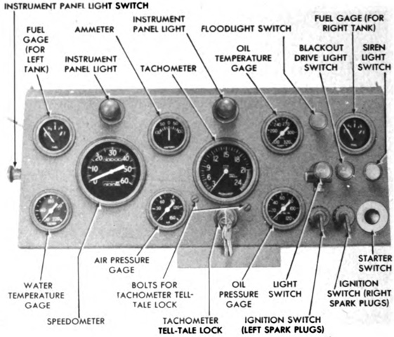
The diver's instrument panel is isolated in this picture. The tachometer tell-tale lock was used to reset the red hand of the tachometer, which remained at the highest rpm the engine had seen. (Picture from TM 9-767 40-ton Tank Transporter Truck-Trailer M25.)
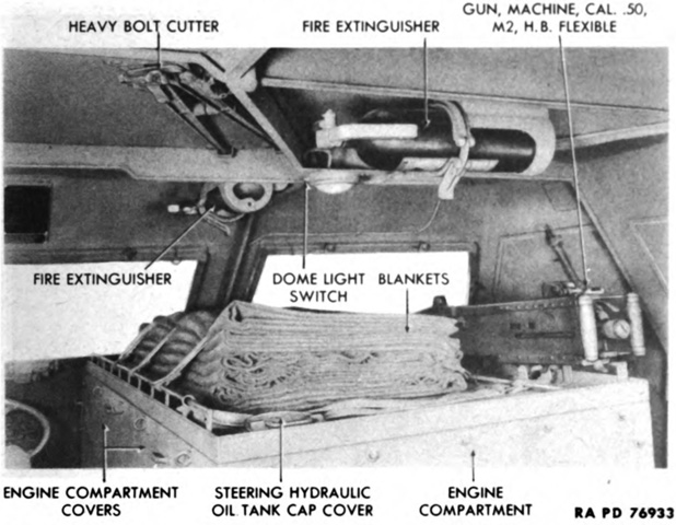
A view of the front of the cab interior is labeled here. The engine was in the middle of the cab and separated the driver and commander. Four portable fire extinguishers were stowed in the cab. (Picture from TM 9-767 40-ton Tank Transporter Truck-Trailer M25.)

The front and rear of the cab's left side are shown on the left and right, respectively. (Picture from TM 9-767 40-ton Tank Transporter Truck-Trailer M25.)
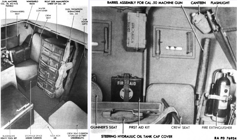
Similar views of the front and rear of the cab's right side are provided on the left and right in this image. (Picture from TM 9-767 40-ton Tank Transporter Truck-Trailer M25.)
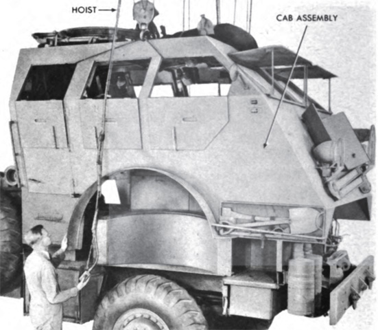
The entire armor assembly of the cab could be dismounted as one unit after various internal fittings had been removed. (Picture from TM 9-767 40-ton Tank Transporter Truck-Trailer M25.)
The right side of the overhead valve engine is seen here with its covers removed. Bore and stroke were 5¾" and 7" (14.6cm and 17.8cm), respectively, for a displacement of 1,090in³ (17.86L). Firing order was 1-4-2-6-3-5. (Picture from TM 9-767 40-ton Tank Transporter Truck-Trailer M25.)
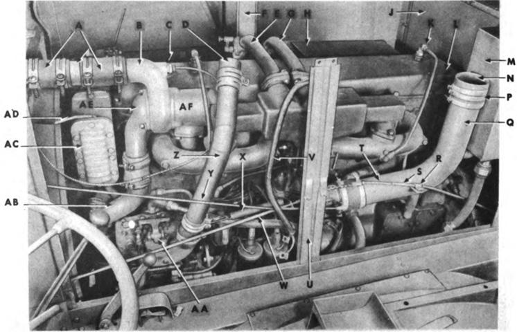
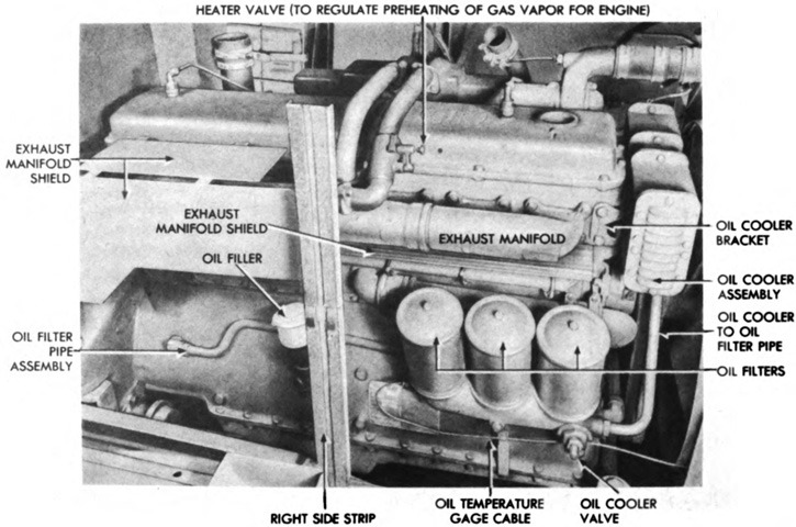
The opposite side of the engine is labeled here. The engine weighed 2,100lb (950kg) with accessories, and could be run at 1,800rpm for sustained periods or 2,100rpm for short periods. A. Radiator top connection. B. Thermostat valve body. C. Water temperature gage cable. D. Hose connection. E. Heater valve pipe assembly. F. Right side strip. G. Heater valve housing pipe. H. Exhaust manifold shield. J. Engine rear cover. K. Rocker arm cover ventilator. L. Rocker arm cover. M. Hydraulic oil tank. N. Hose connection. P. Hose clamp. Q. Carburetor to air duct pipe. R. Clamp. S. Throttle control tubing for tandem winch throttle control cable. T. Tandem winch throttle control cable. U. Left side strip. V. Voltage regulator cable. W. Throttle rod (for hand throttle and accelerator pedal). X. Accelerator rod spring. Y. Choke rod. Z. Air compressor to air duct pipe. AA. Air compressor. AB. Water pump inlet elbow. AC. Oil cooler assembly. AD. Radio filter wire. AE. Thermostat bypass elbow. AF. Water outlet manifold. (Picture from TM 9-767 40-ton Tank Transporter Truck-Trailer M25.)

The engine is shown with the top cover raised. The engine's oil capacity was 6 gallons (23L). A. Radio filter. B. Voltage regulator. C. Voltage regulator ground strap. D. Voltage regulator cable clamps. E. Water temperature tube clamp. F. Connection for air compressor pipe. G. Turnbuckle. H. Air duct. J. Connection for carburetor air pipe. K. Connection for air cleaner pipe. L. Radiator side cover. M. Radiator top hose. N. Connector pipe. P. Hose clamps. Q. Water temperature tube. R. Air compressor to air duct pipe. S. Hose clamp. T. Choke rod. U. Accelerator rod. V. Air compressor. W. Throttle spring. X. Right side strip. Y. Rear winch throttle cable. Z. Clamp. AA. Carburetor to air duct pipe. BB. Hose clamp. CC. Engine rear cover. DD. Engine rear cover frame. EE. Hydraulic oil line (from reservoir to steering gear). FF. Hydraulic oil line (from reservoir to hydraulic pump). GG. Hydraulic oil line (from hydraulic pump to steering gear). HH. Hydraulic oil reservoir filler cap. JJ. Choke control. KK. Radiator. LL. Voltage regulator cable. MM. Right side strip. NN. Engine top cover. PP. Generator. QQ. Radio filter wire. RR. Ignition coils. SS. Air line to governor. TT. Air line to air reservoirs. UU. Fuel line (fuel filter to fuel pump). (Picture from TM 9-767 40-ton Tank Transporter Truck-Trailer M25.)

The muffler is seen from below on the left, with its position on the truck and relative to the exhaust stack apparent on the right. (Picture from TM 9-767 40-ton Tank Transporter Truck-Trailer M25.)
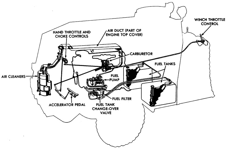
A schematic of the air induction and fuel systems is sketched here. A 50 gallon (190L) fuel tank was installed on each side of the chassis alongside the cab doors. (Picture from TM 9-767 40-ton Tank Transporter Truck-Trailer M25.)
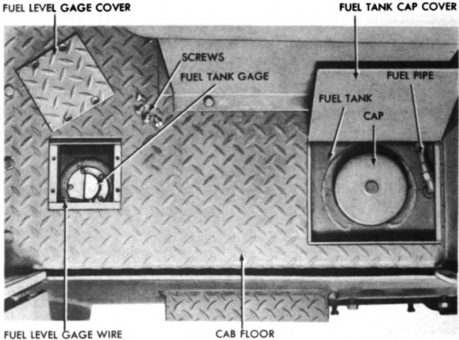
Access to the fuel tank caps was through covers incorporated into the cab floor. (Picture from TM 9-767 40-ton Tank Transporter Truck-Trailer M25.)
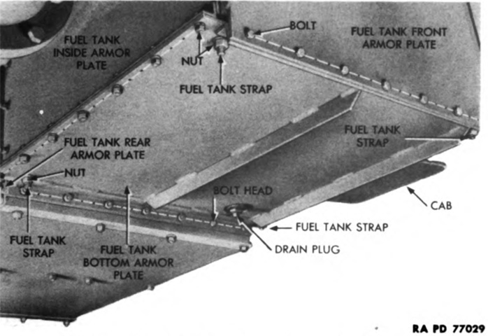
The fuel tanks were protected by armor plates. (Picture from TM 9-767 40-ton Tank Transporter Truck-Trailer M25.)
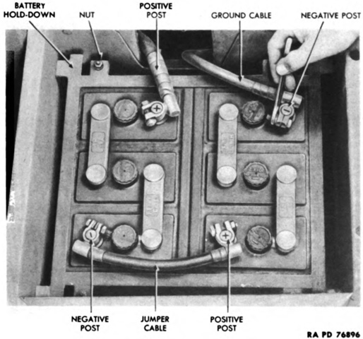
Two six-volt batteries were installed under the crew seat on the cab's right rear wall. They were connected in series to form a 12-volt single-wire system used for lighting and signaling. (Picture from TM 9-767 40-ton Tank Transporter Truck-Trailer M25.)
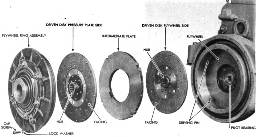
The clutch was a two-plate, dry-disk model manufactured by Lipe Rollway Corporation. The intermediate plate was pinned to the flywheel, and a driven disk was found on each side of the intermediate plate. When the clutch pedal was depressed, the pressure from the driven disks on the intermediate plate was relieved, interrupting power flow from the engine to the transmission. (Picture from TM 9-767 40-ton Tank Transporter Truck-Trailer M25.)
The main transmission was a Fuller 4B86 unit with four forward and one reverse speeds, and was attached by the clutch housing to the flywheel housing at the rear of the engine. A propeller shaft transmitted power from the main transmission to the auxiliary transmission located behind the main transmission. (Picture from TM 9-767 40-ton Tank Transporter Truck-Trailer M25.)
The Spicer 703 Special auxiliary transmission and Timken T96 transfer case mounted on the rear of the auxiliary transmission are shown here removed from the vehicle. The auxiliary transmission was found under the tandem winch assembly, and provided three speed ranges for each of the main transmission's speeds. The auxiliary transmission sent power to the rear wheels via the differential and carrier assembly, and also to the transfer case. Two power take-of assemblies were installed on the auxiliary transmission, one on the top for the tandem rear winches and one on the side for the front winch. (Picture from TM 9-767 40-ton Tank Transporter Truck-Trailer M25.)
The transfer case is shown with the cover removed. It transmitted power to the Timken T77 front axle declutch assembly on the left side of the transfer case, which contained a jaw clutch and propeller shaft that allowed the driver to engage or disengage drive to the front wheels via the front differential and carrier assembly. (Picture from TM 9-767 40-ton Tank Transporter Truck-Trailer M25.)
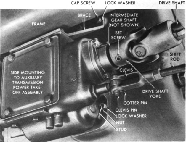
A Spicer ZG5 power take-off was bolted to the right side of the auxiliary transmission case and transmitted power to the front winch through a drive shaft. A shift rod in the driver's compartment was used to obtain low, high, or reverse speeds. (Picture from TM 9-767 40-ton Tank Transporter Truck-Trailer M25.)

The power take-off control handle for the front-mounted winch was found in front of the driver's seat. Gearing on the front-mounted winch was designed so that, with the front winch control lever in low and the cable drum half-way full, the take-up speed was approximately that of the truck with its auxiliary transmission in first speed, giving an underdrive of the main transmission shift. It was therefore possible to use the rear wheels of the truck to add to the winch pull. (Picture from TM 9-767 40-ton Tank Transporter Truck-Trailer M25.)
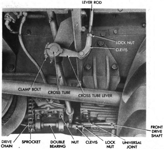
The front winch control linkage is shown here. The drive shaft from the power take-off ended in a sprocket which turned a drive chain looped around a second sprocket on the winch worm shaft. The driver's control handle connected to the power take-off by the lever rods and cross tube. (Picture from TM 9-767 40-ton Tank Transporter Truck-Trailer M25.)
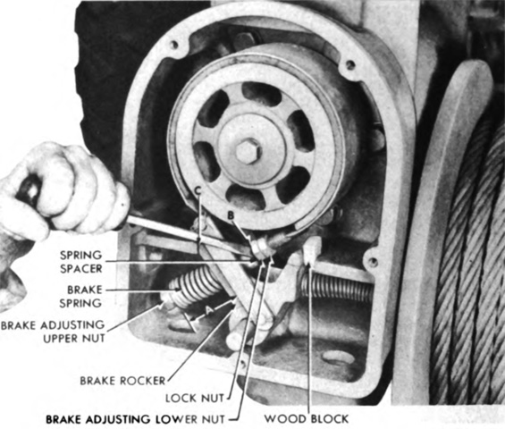
The front winch was equipped with an automatic brake that held the load on the cable to prevent it from being paid out too quickly. The brake is being adjusted in this image; when adjusted correctly, there was ⅛" (.318cm) at dimension B between the spring spacer and the first lower adjusting nut. When properly adjusted, the brake would prevent a load from coming down more than 2" (5.1cm). (Picture from TM 9-767 40-ton Tank Transporter Truck-Trailer M25.)
The front winch is in use helping the truck through poor terrain, which was its primary purpose. Recovery operations could also be performed with this winch, however. A drawbar is stowed on the front of the cab under the radiator shutters. (Picture from TM 9-767 40-ton Tank Transporter Truck-Trailer M25.)

A Spicer 703 power take-off was mounted atop the auxiliary transmission case and transmitted power to either or both of the tandem rear winches. A tandem winch universal joint assembly sent power from the power take-off assembly to a drive sprocket which used a chain to spin a driven sprocket on the tandem winch assembly. (Picture from TM 9-767 40-ton Tank Transporter Truck-Trailer M25.)

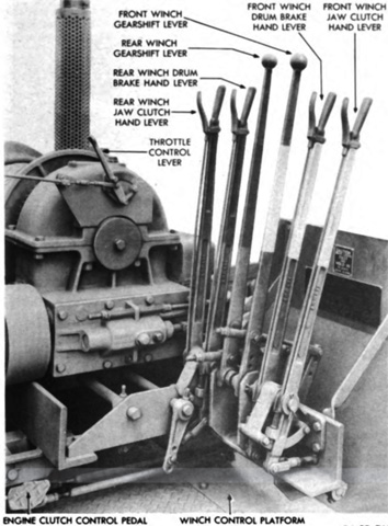
The tandem rear winches were mounted on a single winch base attached to the chassis frame behind the cab. The power take-off winch control lever on the left side of the winch assembly provided neutral, high, and low speeds for the winches, and each winch had its own hand clutch, hand brake, and operating levers. A throttle control lever allowed the winch operator to adjust the truck engine throttle from the winch control platform, and an engine clutch control foot lever was provided to disengage the engine clutch when shifting the power take-off winch control lever. The winch brakes were the same as that found on the front winch. (Picture from TM 9-767 40-ton Tank Transporter Truck-Trailer M25.)
The tandem winch is seen installed; note the orientation of the winches, which is reversed relative to one another. The winch operator platform on the left was protected by a shield. The flood lights above the winches were mounted to the cab rear. (Picture from TM 9-767 40-ton Tank Transporter Truck-Trailer M25.)
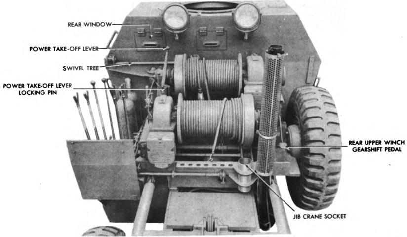
The controls for the tandem rear winches are detailed in this image of the winch operator platform. (Picture from TM 9-767 40-ton Tank Transporter Truck-Trailer M25.)
The rear winches are seen in the process of being removed. A. Power take-off winch control lever. B. Clip. C. Bracket pin. D. Bracket. E. Nut. F. Throttle control cable and tubing. G. Throttle control lever. H. Yoke. J. Quadrant. K. Pin. L. Front tandem winch hand control lever. M. Rear tandem winch hand control lever. N. Rear tandem winch hand brake lever. P. Rear tandem winch hand clutch lever. Q. Rear tandem winch. R. Double lever winch control assembly. S. Clutch control lever. T. Brake control shaft. U. Brake control lever. V. Set screw. W. Cotter pin. X. Hand lever pin. Y. Brake control rod. Z. Rear base angle. AA. End pin. AB. Flat washer. AC. Clutch control rod. AD. Adjusting yoke. AE. Engine clutch control foot lever. AF. Engine clutch control shaft. AG. Clamp bolt (not seen). AH. Rocker lever. AJ. Power take-off winch control rod. (Picture from TM 9-767 40-ton Tank Transporter Truck-Trailer M25.)
The full-floating front axle was a Timken model F 7900-A752 that had a gear ratio of 7.69:1. It was a banjo-type housing within which were the two axle shafts and front differential. The steering tie rod can be seen behind the axle and hub assembly. The front axle could be disengaged by the declutch assembly on the transfer case. (Picture from TM 9-767 40-ton Tank Transporter Truck-Trailer M25.)
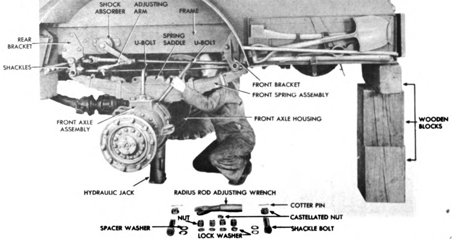
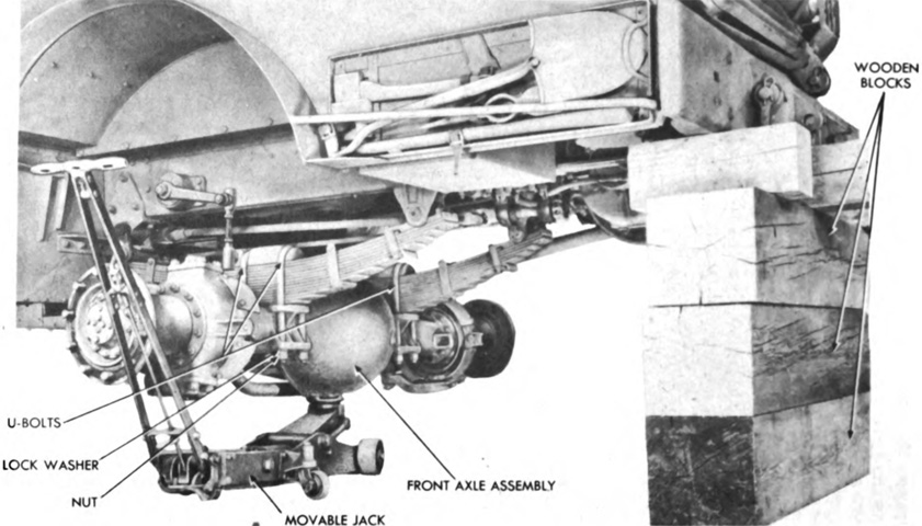
Two semielliptic leaf springs were suspended to frame brackets at the front of the truck by shackles at the rear of the springs and brackets at the front. Each spring was attached to the front axle by two U-bolts and a spring saddle. The front springs are seen here in the process of being removed, with the shock absorber and lower shackle bolt already undone. The front winch driveshaft is visible passing in front of the technician's face. (Picture from TM 9-767 40-ton Tank Transporter Truck-Trailer M25.)
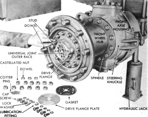
The front wheel hub is seen with the wheel and axle drive flange removed. (Picture from TM 9-767 40-ton Tank Transporter Truck-Trailer M25.)
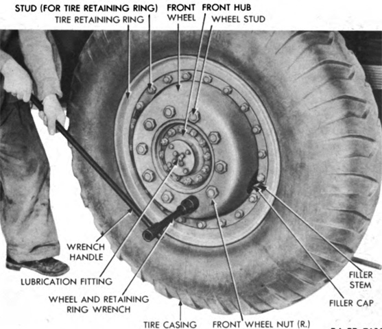
The front wheel is shown in the process of being removed. Wheels were by Budd and tire size was 14.00-24. (Picture from TM 9-767 40-ton Tank Transporter Truck-Trailer M25.)
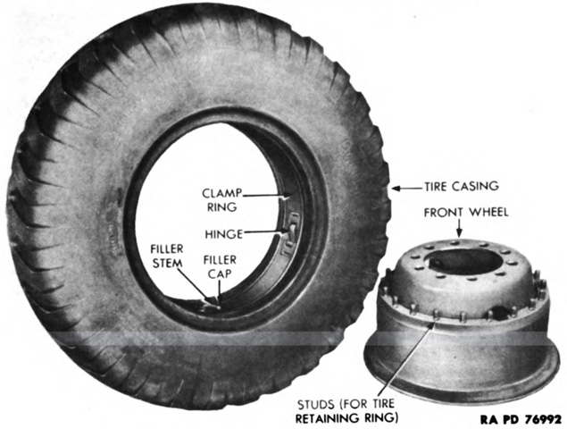
Tires were of the combat or desert type and had puncture-proof inner tubes that were retained in the tire casing by a collapsible ring. Recommended air pressure was 80psi (5.6kg/cm²). (Picture from TM 9-767 40-ton Tank Transporter Truck-Trailer M25.)
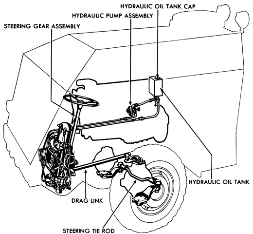
A schematic of the hydraulic power steering system is sketched here. The steering gear was a Ross model 780 unit, while the hydraulic pump was a Bendix model 332872. Bendix also manufactured the hydraulic reservoir, valve, and cylinder. (Picture from TM 9-767 40-ton Tank Transporter Truck-Trailer M25.)
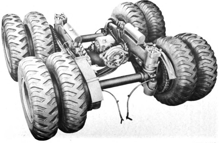
The tandem rear axle has been dismounted from the truck. Power was transmitted to the rear differential and carrier by a propeller shaft from the auxiliary transmission. The rear wheels were chain driven: stationary axle sprockets on the rear wheels were connected by roller chains to jackshaft sprockets on the sides of the Timken 1828B2 differential. The jackshaft sprocket housing was supported on each side by a bushing in the side stabilizer beam. The front and rear carrier axles supported one end of the side stabilizer beam on a stabilizer block, and the other end of the beam on a leaf spring that supported an inner spring case that housed two coil springs. (Picture from TM 9-767 40-ton Tank Transporter Truck-Trailer M25.)

The roller chains are seem looped around the jackshaft drive sprockets and the stationary axle drive sprocket. Tension in the chain is being checked with the straightedge: at the midway point between the sprockets, with a ruler pressing on the chain as far as possible, there was to be 1" (2.5cm) of slack for chains at the coil springs ends and 2" (5.1cm) for the chains at the opposite ends. Mounted on the stabilizer beam above the drive chains is an oil tank with two shut-off valves that was used to lubricate the drive chains when desired by dripping oil onto them via two copper tubes. Behind the oil tank in the image are five lubrication fittings; the front and rear pairs were used to lubricate the jackshaft trunnions, while the center was for the side thrust plate. (Picture from TM 9-767 40-ton Tank Transporter Truck-Trailer M25.)

To adjust tension in the drive chains, the two ball clamp bolts on the affected radius rod were loosened, and the radius rod adjusting wrench was used to loosen or tighten the radius rod until the chain tension was appropriate. (Picture from TM 9-767 40-ton Tank Transporter Truck-Trailer M25.)
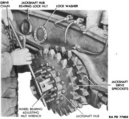
The jackshaft axle hubs are isolated in this picture with the chains and wheels removed. (Picture from TM 9-767 40-ton Tank Transporter Truck-Trailer M25.)

With the dual rear wheels removed, the stationary axle hub and brake drum can more easily be seen. (Picture from TM 9-767 40-ton Tank Transporter Truck-Trailer M25.)
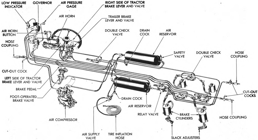
The service brake system is diagrammed in this image. Only the four rear wheels of the truck were equipped with brakes, although the M15 trailer had its own air brake system powered by couplings from the truck. The devices and valves in the system were manufactured by Bendix Westinghouse. (Picture from TM 9-767 40-ton Tank Transporter Truck-Trailer M25.)

The air compressor was a Bendix Westinghouse model 3UE12VW, and it was a 3-cylinder pump located on the left of the engine. The compressor was driven by the engine, lubricated by the engine oiling system, and cooled by the engine cooling system. The compressor would run constantly when the engine was on, but would only compress air when the air pressure governor would cut in. When pressure in the reservoirs reached 100-105psi (7.03-7.38kg/cm²), the governor caused the compressor unloader valves to open. (Picture from TM 9-767 40-ton Tank Transporter Truck-Trailer M25.)
In addition, a Vulcan-Cochin A-FT 4712 two-shoe parking brake acted on the propeller shaft when the driver operated the hand brake lever. (Picture from TM 9-767 40-ton Tank Transporter Truck-Trailer M25.)

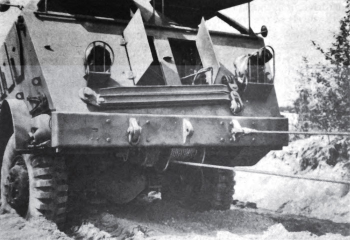
A vertical lifting device was found on the rear of the tractor frame, locked down flat when not in use. It was composed of telescoping side supports that connected to an A-frame, and was primarily used for recovery of vehicles lower than the truck which required a vertical lift instead of a pull. It was also used to raise a tandem winch cable to help prevent it from becoming tangled or getting in the way during recovery operations. The A-frame could be erected by hand, or by backing the truck up to a tree or some other tall implement, looping a rope around the tree and sheave on the A-frame, then driving away until the lifting device was at the desired position. In this image, the crew is locking the lifting device into position. (Picture from TM 9-767 40-ton Tank Transporter Truck-Trailer M25.)

The lifting device could be locked into five positions. The three main positions were vertical, and 18° forward and back of vertical. The two additional positions were between vertical and 18° to the rear. (Picture from TM 9-767 40-ton Tank Transporter Truck-Trailer M25.)

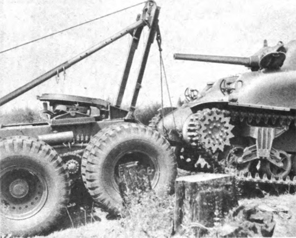
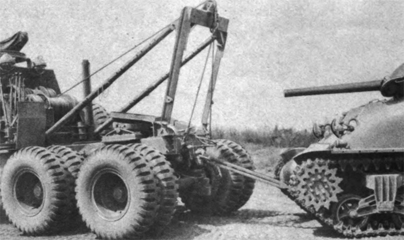
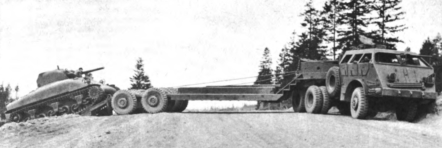
A medium tank M4A1 is being recovered from a lower position than the tractor using the vertical lifting device and the front tandem winch. (Picture from TM 9-767 40-ton Tank Transporter Truck-Trailer M25.)
The vertical lifting device could be used in myriad ways including towing loads such as the M4A1 that was recovered earlier. The jackshaft sprockets and roller chains are visible between the rear wheels, along with the chain oil tank and lubrication fittings. (Picture from TM 9-767 40-ton Tank Transporter Truck-Trailer M25.)
Of course, the rear pintle could be used for towing as well, as shown in this picture with the M4A1 connected by a tow bar. (Picture from TM 9-767 40-ton Tank Transporter Truck-Trailer M25.)
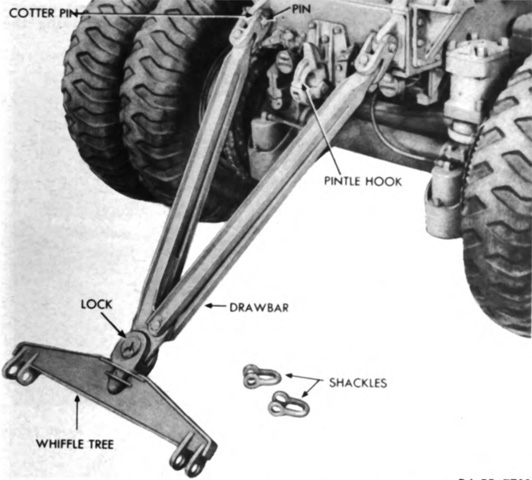
The drawbar stowed on the cab front could be combined with the whiffletree stowed on the cab rear to tow disabled vehicles, or each could be used alone. (Picture from TM 9-767 40-ton Tank Transporter Truck-Trailer M25.)

An integral siren and flashing signal light was mounted on the front left corner of the cab. The light and siren had separate switches at the driver's position. (Picture from TM 9-767 40-ton Tank Transporter Truck-Trailer M25.)
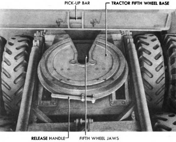
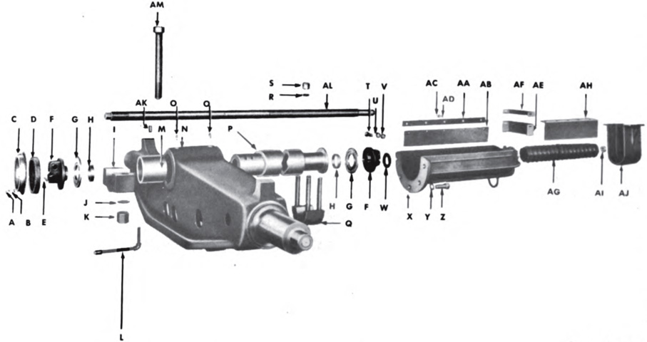
The tractor's fifth wheel was a Fruehauf model F, and had a spring-loaded locking jaw that secured the semitrailer's king pin. A handle actuated the locking jaw. (Picture from TM 9-767 40-ton Tank Transporter Truck-Trailer M25.)
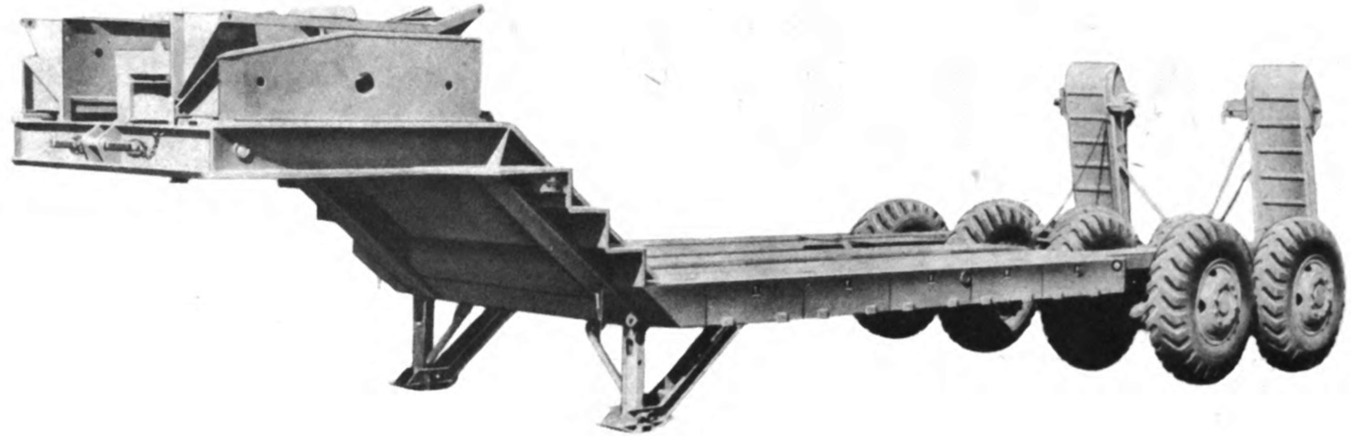
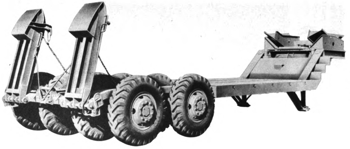
The semitrailer M15 was 38' 5-1/16" (11.71m) long with the permanent ramps raised, and 44'2" (13.46m) with the ramps lowered. It was 12'6" (191cm) wide overall, with the deck being 10'4" (315cm) wide. Overall, the M15 was 8'9" (267cm) tall, with the king pin being 5'7¾" (172.1cm) high. The lower deck was 4'4½" (103cm) high, and ground clearance under the lower deck was 2'5⅛" (73.98cm). Minimum unloaded ground clearance was 13" (33cm), however. The M15 weighed 36,100lb (16,400kg) equipped, and its maximum gross weight was 55,000lb (25,000kg). Stowage boxes were found on the upper deck, and wheel covers were also kept there when not being used for loading vehicles onto the trailer. (Picture from TM 9-767 40-ton Tank Transporter Truck-Trailer M25.)
The M15 used eight single wheels like those found on the tractor. Steps were integrated into the trailer between the upper and lower decks. Tread center to center was 10'11" (333cm). (Picture from TM 9-767 40-ton Tank Transporter Truck-Trailer M25.)

The trailer top decking was used to stow copious amounts of equipment. (Picture from TM 9-767 40-ton Tank Transporter Truck-Trailer M25.)
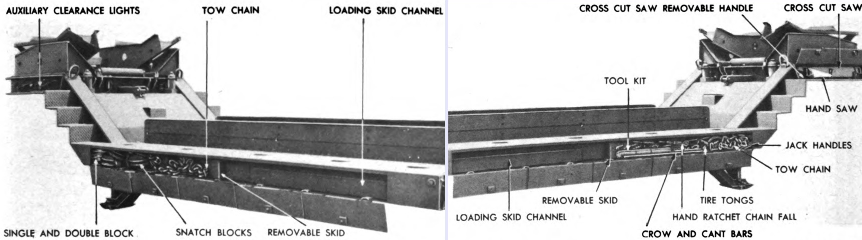
The side rails of the semitrailer were utilized for additional equipment stowage. (Picture from TM 9-767 40-ton Tank Transporter Truck-Trailer M25.)
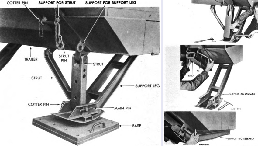
Two support legs were attached to the front of the semitrailer for use when not coupled to the tractor. In the right image, the support leg is being secured in the raised position. The angle at the end of the support leg allowed it to fit flush to the underside of the semitrailer deck. (Picture from TM 9-767 40-ton Tank Transporter Truck-Trailer M25.)

The rear underconstruction of the trailer could be extended or narrowed to accommodate loading vehicles of different widths. Once the side rails were removed and the trailer frame was raised 1-2" (2.5-5.1cm) by the use of a jack, the shifting screw locking bolt was loosened, which allowed the use of the shifting screw wrench to move the underconstruction inward up to 13" (33cm) on each side, reducing the trailer's overall width to 10'4" (315cm). However, the tires would rub on the trailer frame if it was driven at a width under 10'6" (320cm). (Picture from TM 9-767 40-ton Tank Transporter Truck-Trailer M25.)
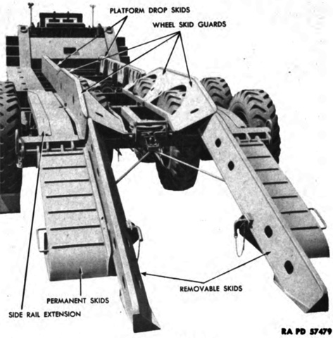
The permanent skids are lowered in this image. Their oversized hinges allowed them to be moved laterally to account for treads of different loaded vehicles. Removable skids could be attached to the permanent skids when loading disabled tanks. Similarly, platform drop skids could be installed on the lower semitrailer decking to assist in loading. A series of holes in the M15's cross members permitted adjusting the lateral placement of the drop skids. The wheel skid guards were installed over the inner four wheels of the trailer to protect the tires when loading tanks. (Picture from TM 9-767 40-ton Tank Transporter Truck-Trailer M25.)
A walking beam was found on each side of the trailer, hinged to the side rails by a mounting bracket and a trunnion shaft that allowed the walking beam to move in a longitudinal direction. The trailer's brake cylinders were housed in the hollow sections of the walking beams for protection.
A. ¼" (.64cm) round head slotted screw. B. ¼" (.64cm) lock washer. C. Dust felt cover. D. Dust felt. E. 3/16" x 2½" (.4763cm x 6.4cm) cotter pin. F. Special nut. G. Trunnion shaft washer. H. Spacer. I. Outside trunnion shaft cap. J. Lock washer. K. Cap bolt nut. L. Walking beam bushing lubrication line. M. Walking beam bushing. N. Walking beam (rocker arm). O. Bushing dowel pin. P. Trunnion shaft. Q. Trunnion shaft cap and studs. R. Lock washer. S. Nut. T. 7/16" (1.111cm) cap screw. U. 7/16" (1.111cm) lock washer. V. 7/16" (1.111cm) castellated nut. W. Felt washer. X. Shifting bracket. Y. ¾" (1.9cm) lock washer. Z. ¾" (1.9cm) cap screw. AA. Side weather strip mounting plate. AB. Side weather strip. AC. 5/16" (.7938cm) cap screw. AD. 5/16" (.7938cm) lock washer. AE. End weather strip. AF. End weather strip mounting plate. AG. Shifting screw rubber boot. AH. Protection plate. AI. Retainer collar. AJ. U-bracket. AK. Trunnion shaft dowel pin. AL. Walking beam shifting screw. AM. Trunnion shaft cap nut. (Picture from TM 9-767 40-ton Tank Transporter Truck-Trailer M25.)

The M15 used trunnion-type axles that oscillated on a spindle at each end of the walking beam, permitting the wheels movement in both the transverse and longitudinal directions. (Picture from TM 9-767 40-ton Tank Transporter Truck-Trailer M25.)
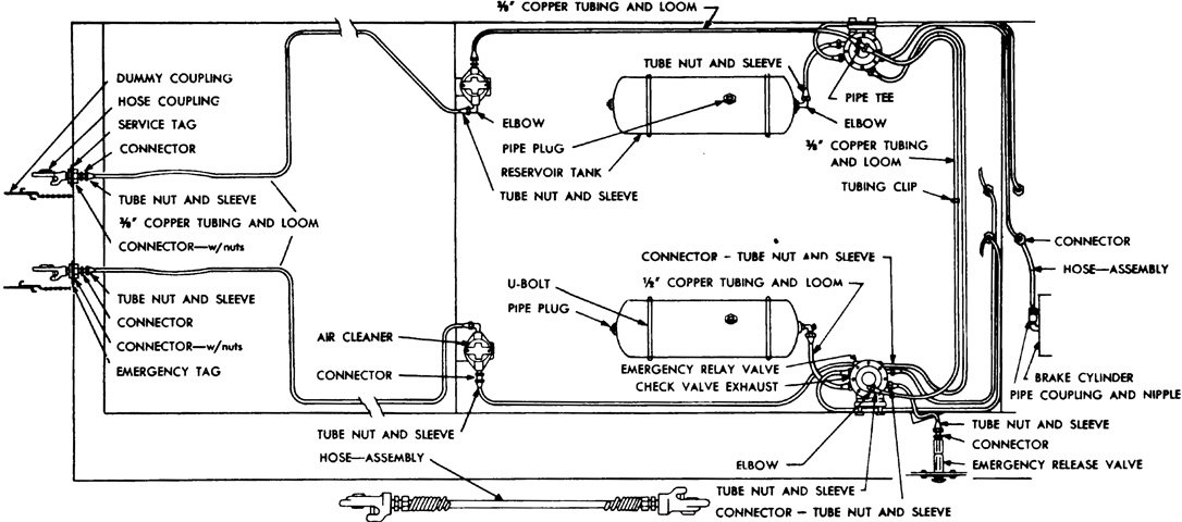
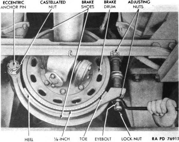
The M15's brake system is diagrammed in this sketch. It used 16" x 6" (41cm x 15cm) heavy-duty, mechanical, internal expanding, two-shoe, ribbed-drum, eccentric anchor pin type brakes that worked via the cam and lever principle. Four air cylinders in the hollow sections of the walking beams actuated the brakes, with each cylinder braking two wheels. If the semitrailer broke away from the tractor, its brakes would hold it for a limited time. (Picture from TM 9-767 40-ton Tank Transporter Truck-Trailer M25.)
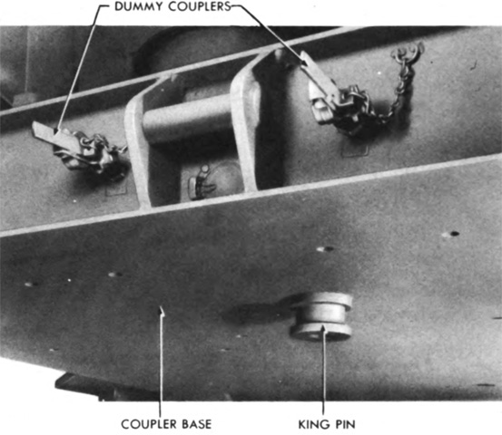
The M15's king pin is highlighted in this image; the tractor was backed up to the semitrailer with its fifth wheel and the M15's king pin covered in grease, then after being aligned the tractor was reversed until the king pin was settled in the fifth wheel jaws. The jaws were then checked to make sure they were locked so that the trailer did not come loose. Connections for the trailer's service and emergency air brake lines are on either side of the pick-up bar. Inside the bracket for the pick-up bar is the trailer's jumper cable light socket. (Picture from TM 9-767 40-ton Tank Transporter Truck-Trailer M25.)
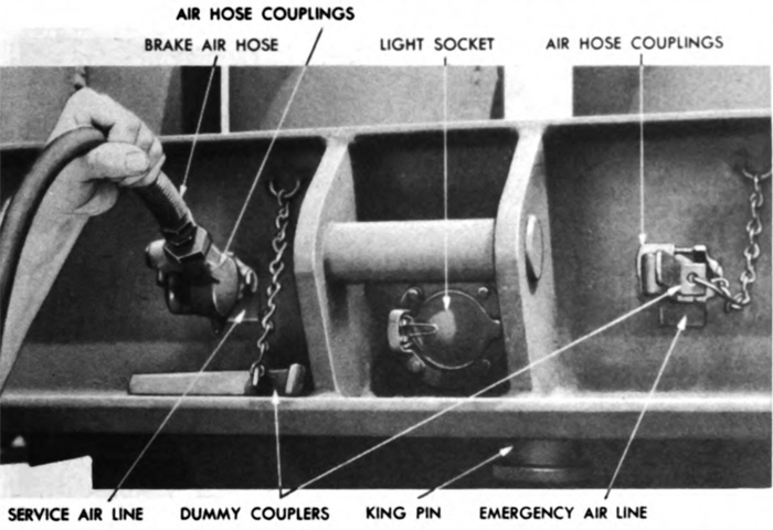
A closer look at the M15's air line and electrical connections is provided in this picture. The dummy couplers were attached to the air hose couplings when the trailer was standing alone so that the couplings would not become damaged. (Picture from TM 9-767 40-ton Tank Transporter Truck-Trailer M25.)
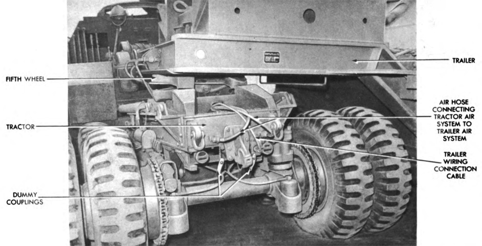
The tractor has been driven so that the trailer is 90° to the right. From this angle, the air hose connections from the tractor to the semitrailer can be seen. Skids were present on the tractor frame behind the fifth wheel to ease the mounting of the trailer. (Picture from TM 9-767 40-ton Tank Transporter Truck-Trailer M25.)
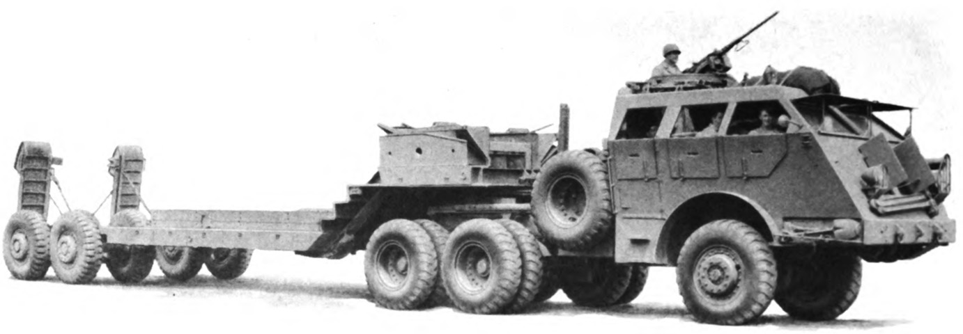
Until October 1944, the tractor and semitrailer were known as the 40-ton tank transporter truck-trailer M25 when coupled together, but after that date the practice of naming the combination was discontinued. The wheelbase of the combination was 45'4" (13.8m) from the center of the front wheel to the center between the front and rear semitrailer wheels. (Picture from TM 9-767 40-ton Tank Transporter Truck-Trailer M25.)

The coupled tractor-semitrailer is seen from the opposite angle. (Picture from TM 9-767 40-ton Tank Transporter Truck-Trailer M25.)

Our hapless M4A1 is being winched onto the M15 trailer by the tractor's rear tandem winches. The tracks fit between the trailer wheels, and the wheel guards are not installed. (Picture from TM 9-767 40-ton Tank Transporter Truck-Trailer M25.)
The trailer had both vertical and horizontal cable rollers and sheaves, so it was possible to recover a disabled vehicle using the tractor winches when the trailer was at an angle. (Picture from TM 9-767 40-ton Tank Transporter Truck-Trailer M25.)
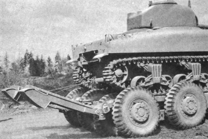
The semitrailer's permanent skids could be raised by hand or by attaching the skids to the tank being loaded, so that the skids were raised as the tank was pulled onto the semitrailer. (Picture from TM 9-767 40-ton Tank Transporter Truck-Trailer M25.)

A crane and hoist were stowed disassembled on the lower deck of the semitrailer, and could be installed in one of four sockets/pockets on the trailer or at the right rear of the tractor near the corner of the tandem winch frame. It had a lifting capacity of ½ ton (450kg), and was primarily used with tire tongs when changing the inner trailer wheels or mounting or dismounting the spare wheel on the tractor. It could also be used for changing or installing major semitrailer or tractor components. Note the handle on the open door of the tractor: the outer handle was at the bottom of the door while the inner handle was near the top. The two handles were connected by the linkage visible on the inside of the door. (Picture from TM 9-767 40-ton Tank Transporter Truck-Trailer M25.)

With the introduction of wider and heavier tanks such as the M26 Pershing, the M15 was modified to cope with their increased weight and width. The M15A1 was 42,370lb (19,220kg) net with a 90,000lb (40,800kg) payload. Permanent hinged ramps, raised in this illustration, were provided over the wheels to protect the semitrailer tires from the tank tracks. (Picture from TM 9-500 C3 Data Sheets for Ordnance Type Materiel.)

A better look at the raised ramps over the trailer wheels is provided from this angle. Stakes could be installed along the trailer sides when hauling non-vehicle loads or supplies. Instead of the hinged covers over the stowage in the side rails, panels have been welded to the trailer with oval access holes. (Picture from Catalogue of Standard Ordnance Items, 2nd edition 1944, volume 1.)
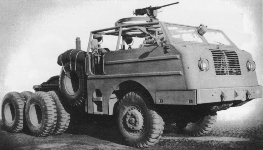
The unarmored cab of the M26A1 presents a stark contrast to the earlier version. The tool stowage ahead of the front wheels was now enclosed, and with no roof on which to mount the spotlight, it was moved to between the two windshields. The side steps and headlights were inset into the bodywork, and the blackout marker headlight and combination siren and signal light were behind the radiator grille. (Picture from Catalogue of Standard Ordnance Items, 2nd edition 1944, volume 1.)
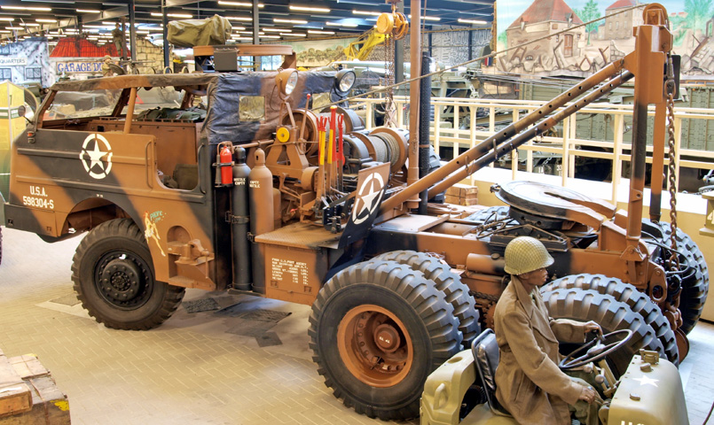
A canvas cover has been emplaced overtop of the open cab on this machine. With the fifth wheel tilted to the rear it is possible to see how the skids on the chassis frame matched the angle of the fifth wheel as the trailer transitioned from one to the other. Since the rear of the cab was also open, the floodlights have been mounted on the upper tandem winch. The vise is also present on this truck behind the side steps. (Picture by AlfvanBeem.)
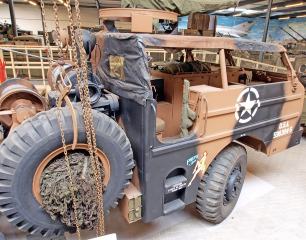
Similarly to the floodlights, the flare stowage boxes were necessarily moved from their original position high on the cab rear to the bottom rear of the cab just in front of the spare wheel. Inside the cab, a .45 caliber submachine gun is secured by the door, and the engine compartment has blankets strapped to its top. (Picture by AlfvanBeem.)

This M26A1 is pulling an M15A1 semitrailer. Cable rollers are visible on the upper deck of the trailer and between the permanent skids, and the oversize skid hinges illustrate how the skids could be moved to accept tanks with different tread widths. The protective wheel ramps are secured in the raised position. (Picture by T. W. Kines; available from the National Archives.)

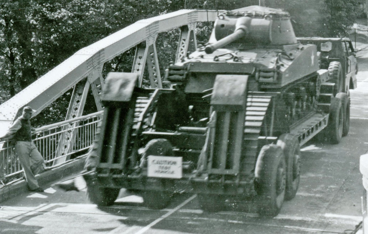
The .50cal machine gun mount has not been installed, but the location of the siren and light behind the radiator grille can be seen. A 90mm GMC M36B1 is being driven across a bridge on US Route 60 in Pennsylvania to demonstrate the bridge's strength. Though only designed for H20 loading, infrequent loads as heavy as the loaded tank transporter could be handled. (Picture taken by T. W. Kines in 1948; available from the National Archives.)
Seen from behind, the M36B1's position relative to the raised wheel ramps can be better ascertained. (Picture taken by T. W. Kines in 1948; available from the National Archives.)
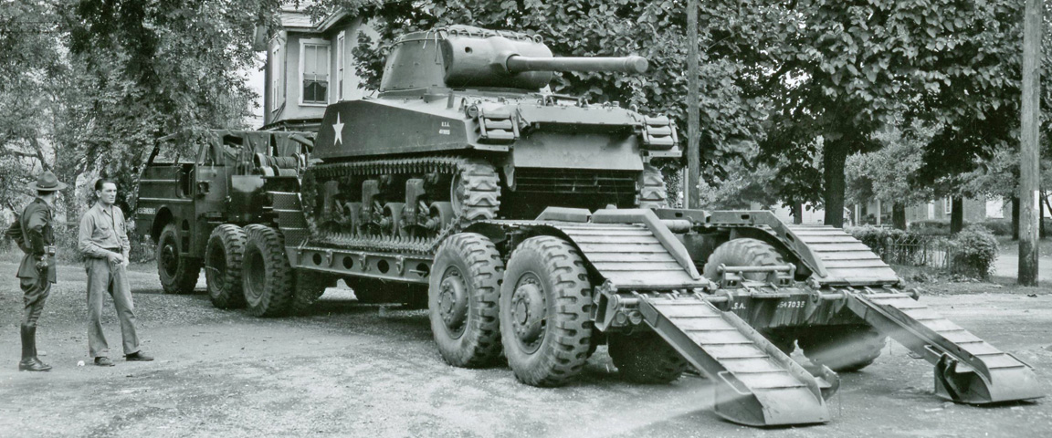
The wheel ramps have been lowered in preparation for unloading the M36B1, showing how a continuous surface over the semitrailer wheels was obtained. A Pennsylvania state trooper is seen talking to the driver of the M26A1, named Hassinger from Letterkenny Ordnance Depot. (Picture taken by T. W. Kines in 1948; available from the National Archives.)
