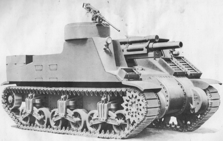
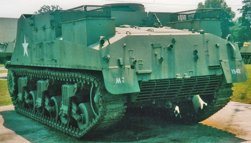
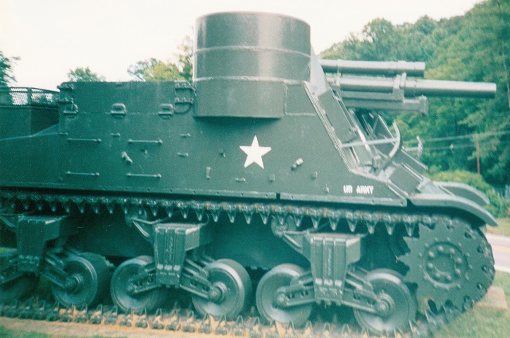
105mm Howitzer Motor Carriage M7.
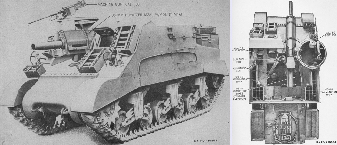
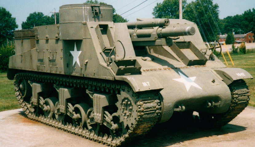
It's obvious how the 105mm HMC M7 acquired the nickname of "Priest" when one notes the pulpit-like .50cal machine gun mount to the right of the howitzer. This machine has the early three-piece final drive and differential cover and the early suspension bogies with smaller springs and return rollers directly on top of the bogie frames. The final drive and differential cover has the notch in the upper right corner to provide room for the medium tank M3's 75mm gun. Track grousers are stowed in the boxes on the hull front, and additional stowage boxes are mounted on the hull rear. (Picture from TM 9-731E 105-mm Howitzer Motor Carriage M7.)
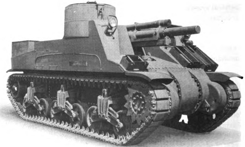
Design changes were approved on 5 May 1942 that included adding a lower section to the machine gun position, thereby increasing room for the machine gunner. (Picture from TM 9-2800 Standard Military Motor Vehicles.)
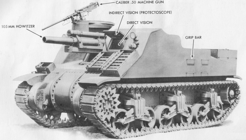
The crew mounted the vehicle over the side, and grip bars were provided on both sides to ease this task. The machine gun is stowed in its travel lock. Note the riveted lower hull between the suspension bogies. (Picture from TM 9-731E 105-mm Howitzer Motor Carriage M7.)
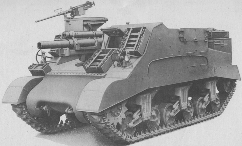
This later-production machine showcases improvements inherited from the medium tank program such as the single-piece final drive and differential cover and heavy-duty suspension bogies. Hinged armor flaps have been added to the sides to protect the howitzer ammunition. Note also the changed location of the headlights and track grouser stowage boxes. (Picture from TM 9-731E Carriage, Motor, 105-mm Howitzer, M7.)
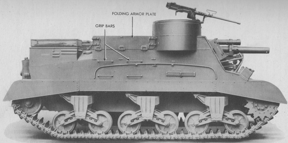
The rearward position of the track return rollers and the folding armor plates are more easily seen in this side view. Baskets have been added to the stowage boxes on the hull rear. (Picture from TM 9-731E Carriage, Motor, 105-mm Howitzer, M7.)
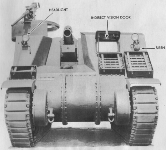
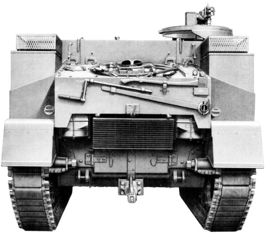
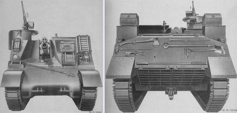
The ordnance was offset to the vehicle's right, which can easily be seen in this head-on view. (Picture from TM 9-731E 105-mm Howitzer Motor Carriage M7.)
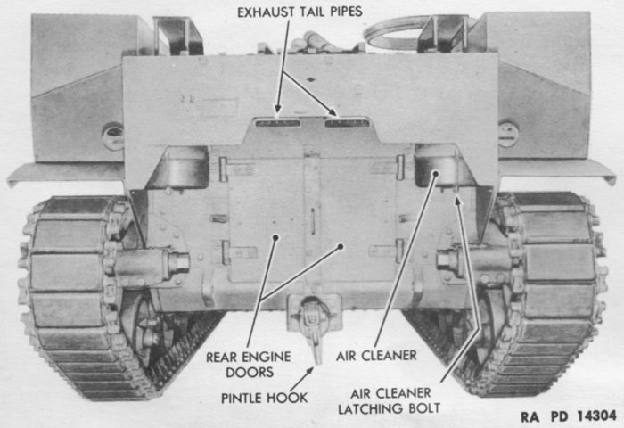
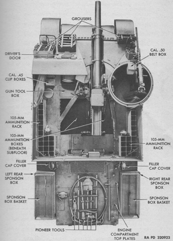
The rear of the carriage is reminiscent of the medium tank M3 whence it was derived. Stowage boxes are mounted on the rear outboard corners of the hull. (Picture from TM 9-731E 105-mm Howitzer Motor Carriage M7.)
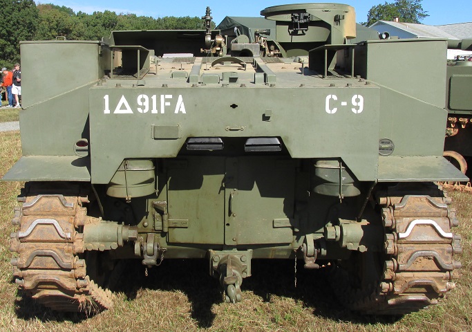
The rear of a restored vehicle is shown here and can be compared with the technical manual illustration.
Note the different rear armor plate configuration on this later-production machine as well as the presence of an exhaust deflector. (Picture from ORD 7-8-9 SNL G-128.)
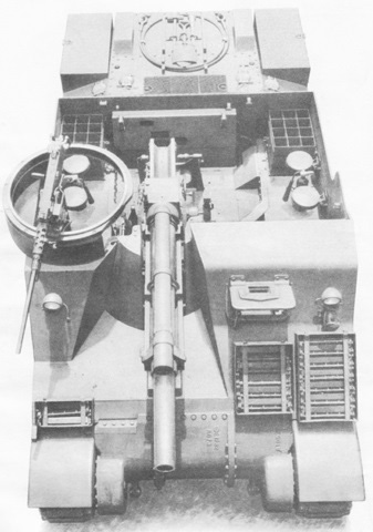
The positioning of the machine gun and howitzer relative to the crew compartment can be seen in this overhead view. (Picture from TM 9-731E 105-mm Howitzer Motor Carriage M7.)
Pioneer tools were stowed on the rear hull, and the positioning of the howitzer mount can be seen. The mount was installed facing slightly to the right in order to increase the available traverse when in the motor carriage. Note that there are enough folding seats for the entire crew. (Picture from TM 9-731E 105-mm Howitzer Motor Carriage M7.)
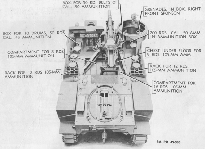
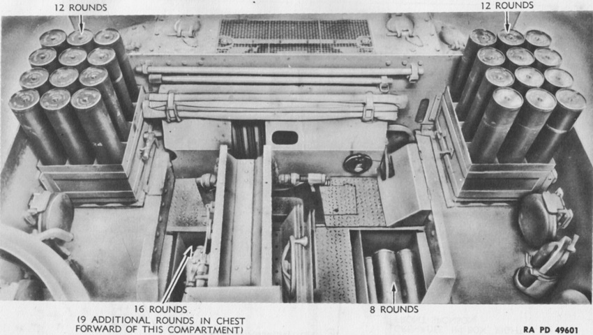
Ammunition stowage for an early-production vehicle is detailed in this diagram. (Picture from TM 9-731E 105-mm Howitzer Motor Carriage M7.)
Howitzer ammunition is shown here present in its racks. The two 4lb (1.8kg) Walter Kidde & Co., Inc., 4T CO2 portable fire extinguishers are visible in their mounting racks on each side of the crew compartment, although the extinguisher on the carriage's right side is mostly obscured by the machine gun traversing ring. (Picture from TM 9-731E 105-mm Howitzer Motor Carriage M7.)
In this late carriage, additional ammunition racks have replaced four of the folding crew seats. (Picture from TM 9-731E Carriage, Motor, 105-mm Howitzer, M7.)
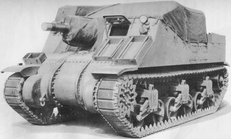
Like all American self-propelled artillery of the era, the M7 was open-topped. A canvas cover could be mounted when needed. Separate covers were also available for the machine gun and howitzer breech. (Picture from TM 9-731E 105-mm Howitzer Motor Carriage M7.)
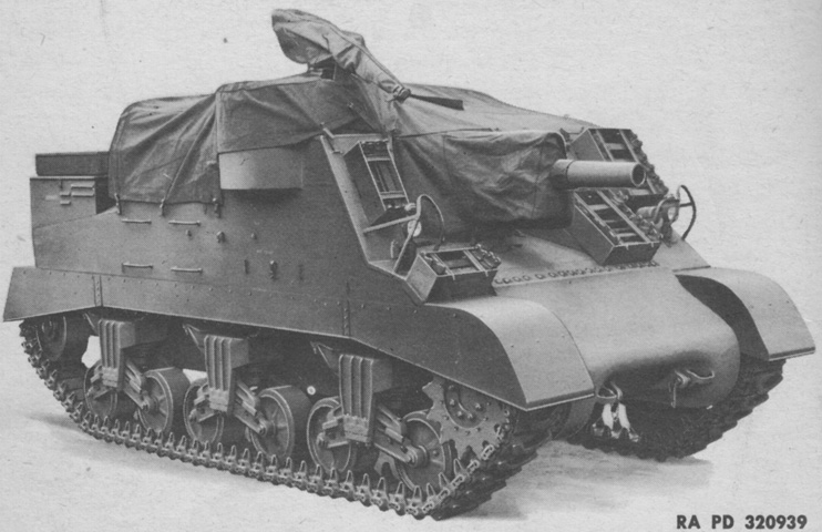
The cover for the mounted machine gun is shown here. (Picture from TM 9-731E Carriage, Motor, 105-mm Howitzer, M7.)
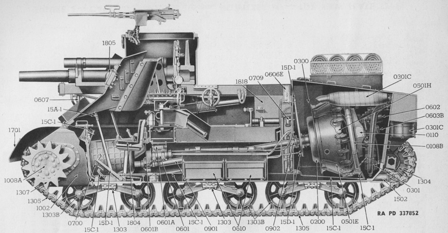
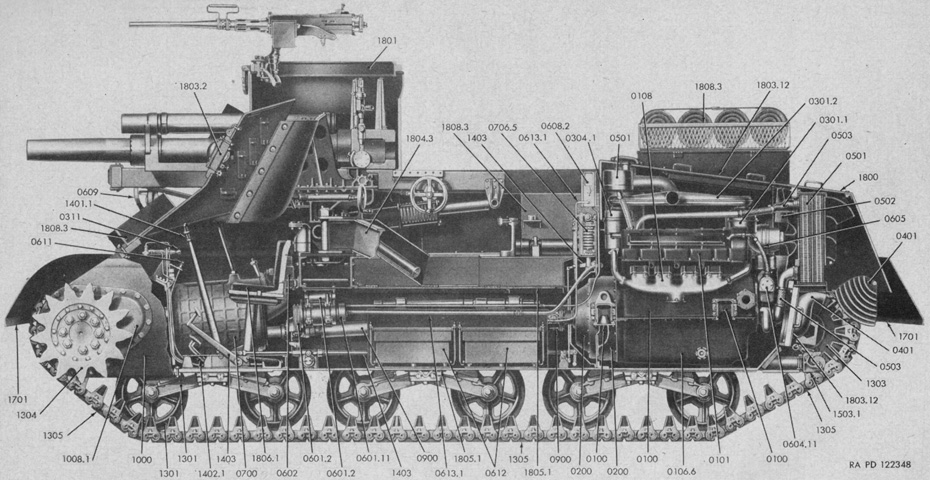
This cross-section highlights the driveline from the angled rear-mounted engine to the front transmission and sprockets. The fighting compartment floor was above the propeller shaft, obviating the need to work around it while servicing the howitzer. (Picture from ORD 7-8-9 SNL G-128.)
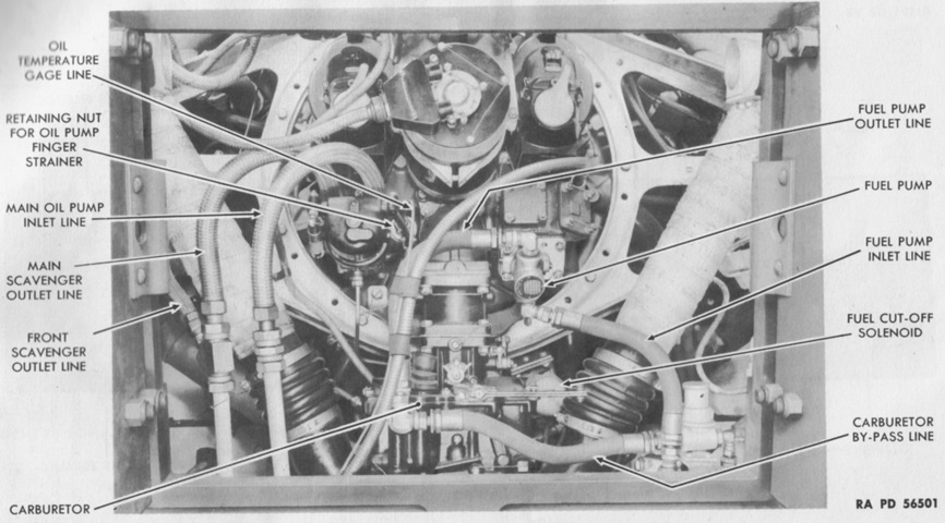
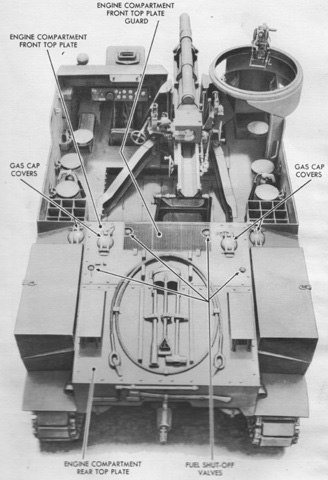
Details of the radial engine are labeled as seen through the open rear engine compartment doors. (Picture from TM 9-731E 105-mm Howitzer Motor Carriage M7.)
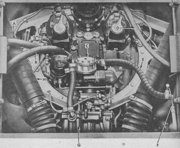
The same view from a late-production machine can be compared. A. Main scavenger outlet tube. B. Oil line inlet tube. C. Fuel pump. D. Cranking motor wiring harness. E. Fuel inlet tube. F. Primer distributor line. G. Carburetor. H. Lower air intake tube. (Picture from TM 9-731E Carriage, Motor, 105-mm Howitzer, M7.)
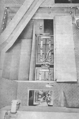
Two 12-volt storage batteries were connected in series to create a 24-volt electrical system. The battery compartment was under the left side of the crew compartment floor. (Picture from TM 9-731E 105-mm Howitzer Motor Carriage M7.)
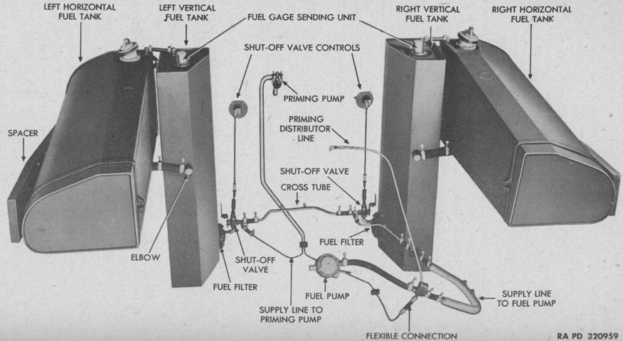
Two vertical fuel tanks of 30gal (110L) capacity each and two horizontal tanks of 58gal (220L) capacity each were located in the engine compartment. (Picture from TM 9-731E Carriage, Motor, 105-mm Howitzer, M7.)
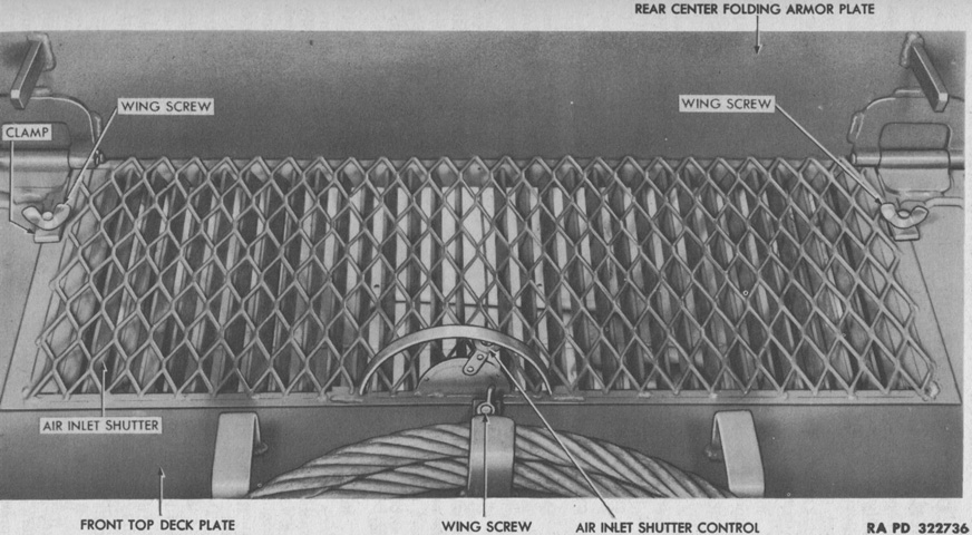
The front air inlet shutter in the front engine cover plate allowed the amount of cooling air ingested into the engine compartment to be regulated. The vanes could be moved from fully open to fully closed. (Picture from TM 9-731E Carriage, Motor, 105-mm Howitzer, M7.)
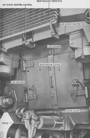
Similarly, an outlet shutter above the rear engine doors regulated how much cooling air was expelled. Note the exhaust deflector on this late-production carriage, which is raised and secured out of the way. (Picture from TM 9-731E Carriage, Motor, 105-mm Howitzer, M7.)
The driver was seated below and to the left of the howitzer mount. (Picture from TM 9-731E 105-mm Howitzer Motor Carriage M7.)
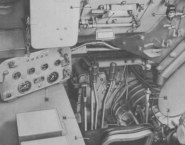
Changes made during production to the driver's position can be gleaned from comparison with this picture. A. Driver's door. B. Protectoscope. C. Compass. D. Primer pump. E. Hand throttle. F. Horn switch. G. Steering brake control levers. H. Gearshift lever. J. Tachometer adapter. K. Accelerator pedal. L. Driver's seat. M. Clutch pedal. N. Instrument panel. (Picture from TM 9-731E Carriage, Motor, 105-mm Howitzer, M7.)
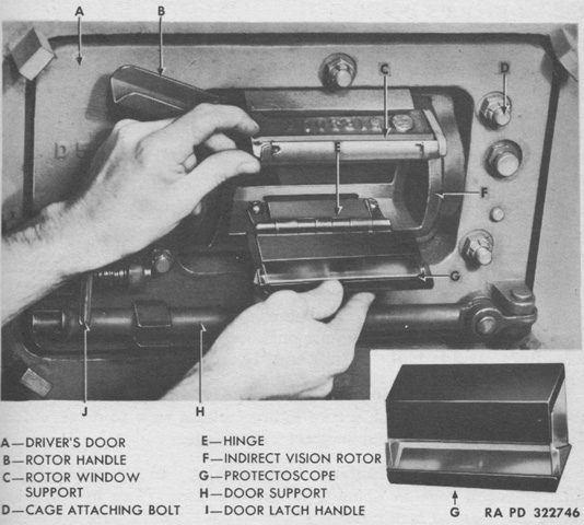
The installation of the driver's protectoscope is illustrated in this picture. (Picture from TM 9-731E Carriage, Motor, 105-mm Howitzer, M7.)
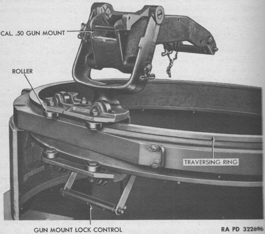
Details of the machine gun mount, which appears to be using cradle and pintle assembly 7068880, can be seen in this image. This was capable of elevation from +85° to -30°. The earlier cradle and pintle assembly D69802 was also used on medium tanks, and had a spring-assisted yoke capable of being set in two positions. The forward position allowed the machine gun to be elevated from +47° to -30°, while the rear position allowed +75° to +35° of elevation. (Picture from TM 9-731E Carriage, Motor, 105-mm Howitzer, M7.)
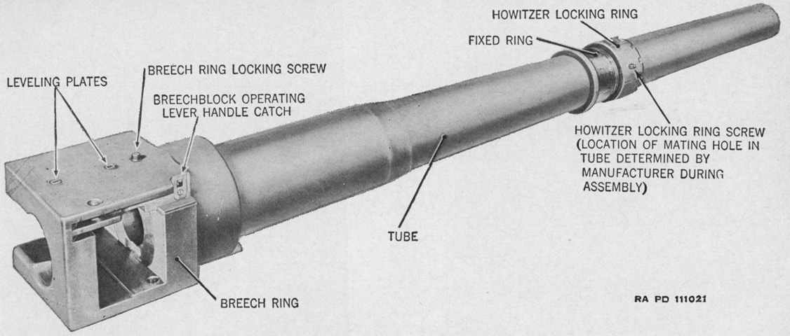
The barrel group of the howitzer M2A1 is isolated in this picture. It consisted of the tube assembly, breech ring, and the howitzer locking ring. (Picture from TM 9-325 C8 105-mm Howitzer M2A1, Carriages M2A1 and M2A2, and Combat Vehicle Mounts M4 and M4A1.)
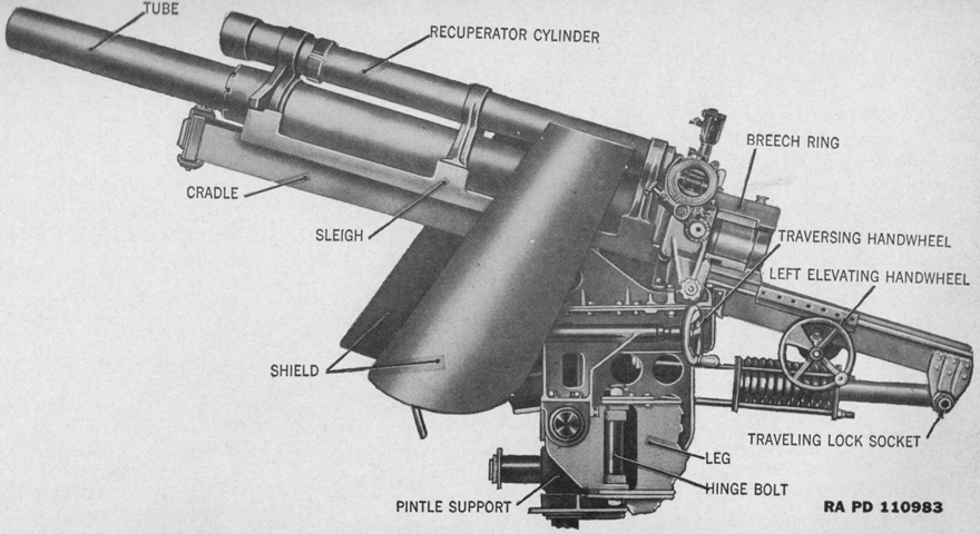
The 105mm howitzer M2A1 is shown here in its mount M4. The weight of the howitzer tube and its breech mechanism was ~1,064lb (~482.6kg). The mount M4 was 9' (274cm) long, 3'8" (112cm) wide, and 3'1" (94cm) tall. (Picture from TM 9-325 C8 105-mm Howitzer M2A1, Carriages M2A1 and M2A2, and Combat Vehicle Mounts M4 and M4A1.)
Details of the howitzer mount are given here. It took 35.5 revolutions of the elevation handwheel to elevate the howitzer 20°, and 19 revolutions of the traverse handwheel to traverse the ordnance 20°. Note that an elevation handwheel was provided on each side of the howitzer mount. (Picture from TM 9-731E 105-mm Howitzer Motor Carriage M7.)
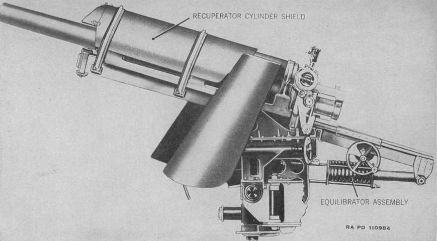
The later mount M4A1 added a shield for the recuperator cylinder. The M4A1 was 9'4" (284cm) long and 3'5" (104cm) tall, and a heavier equilibrator spring was used to make up for the added weight of the recuperator cylinder shield. (Picture from TM 9-325 C8 105-mm Howitzer M2A1, Carriages M2A1 and M2A2, and Combat Vehicle Mounts M4 and M4A1.)
The howitzer mount M4A1 is seen installed from the left front and from above. (Picture from TM 9-325 C8 105-mm Howitzer M2A1, Carriages M2A1 and M2A2, and Combat Vehicle Mounts M4 and M4A1.)
The only way the howitzer would fire was by pulling the lanyard. As a safety feature, if the ordnance failed to completely return to battery, the lug on the firing shaft would not engage with the trigger shaft. (Picture from TM 9-731E Carriage, Motor, 105-mm Howitzer, M7.)
The action of the firing lock M13 is illustrated in these cross-sectional views. When the lanyard was pulled, the firing shaft was drawn to the rear, and a pawl at the front of the firing shaft also moved the trigger shaft arm rearward. As the trigger shaft moved to the rear, it rotated clockwise and moved the trigger fork toward the front. The frontward motion of the trigger fork also forced the firing pin holder sleeve forward, which compressed the firing spring. The sleeve's forward motion then tripped the sear, releasing the firing spring holder and allowing the compressed firing spring to expand, snapping the firing pin forward, which then impacted the primer of the cartridge case. The firing spring expanded both to the front and rear, and the rearward pressure forced the trigger fork and the holder sleeve to the rear until the sear was again engaged. (Picture from TM 9-325 C8 105-mm Howitzer M2A1, Carriages M2A1 and M2A2, and Combat Vehicle Mounts M4 and M4A1.)
The howitzer cradle weighed 333lb (151kg). (Picture from TM 9-731E 105-mm Howitzer Motor Carriage M7.)
The recoil mechanism and sleigh are shown here with the ordnance dismounted. (Picture from TM 9-731E 105-mm Howitzer Motor Carriage M7.)
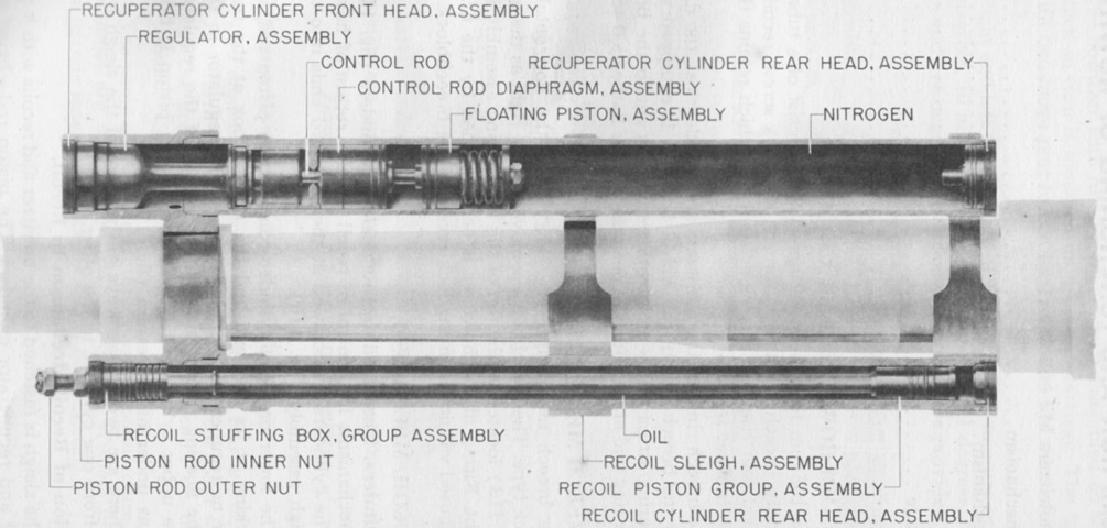
A cross-section of the recoil system is diagrammed in this picture. The recoil mechanism weighed 463lb (210kg), with the recuperator weighing 72lb (33kg). The normal recoil stroke was 42" (110cm). (Picture from TM 9-731E 105-mm Howitzer Motor Carriage M7.)
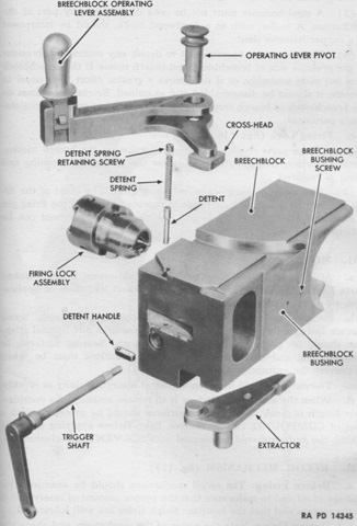
An exploded view of the beech mechanism is shown here. In contrast to that found on the 105mm howitzer M2, the breech ring of the howitzer M2A1 had two bronze bearing strips inserted into dovetail slots cut into the bottom of the breech ring that were secured by four flathead screws. (Picture from TM 9-731E 105-mm Howitzer Motor Carriage M7.)
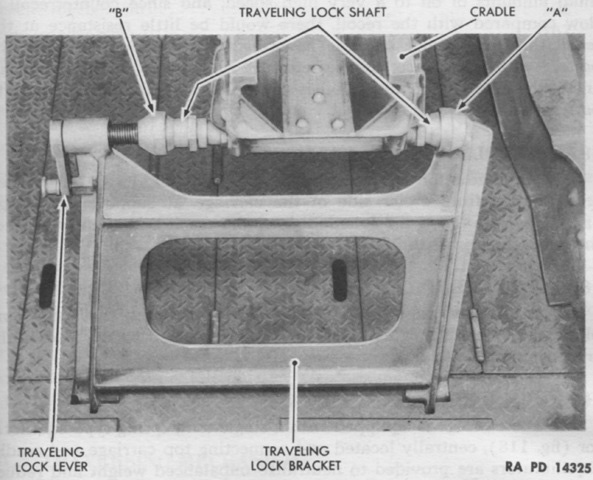
The howitzer travel lock was disengaged by turning the traveling lock lever counterclockwise until socket "B" cleared the locking shaft ball end. The howitzer was then traversed until socket "A" was clear of the lock, and once this occurred the traveling lock bracket was lifted out and stowed. (Picture from TM 9-731E 105-mm Howitzer Motor Carriage M7.)
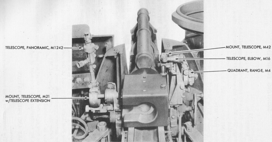
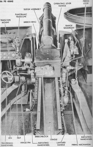
The sighting equipment is shown installed in this picture. (Picture from TM 9-731E 105-mm Howitzer Motor Carriage M7.)
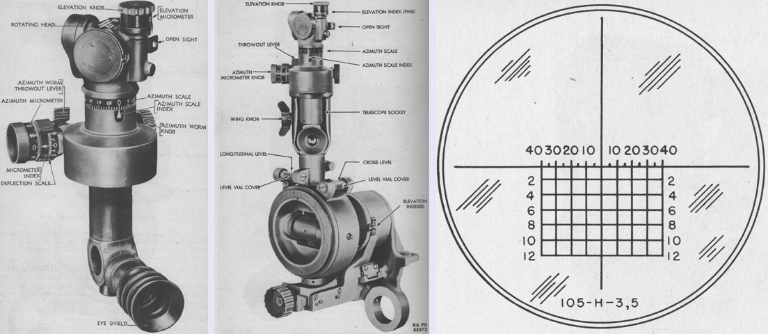
The panoramic telescope M12A2 is shown isolated on the left and installed in the telescope mount M21 in the center, and its reticle pattern is sketched on the right. The M12A2 was a 4x fixed-focus, erect-image, vertical telescope with a 10° field of view. The top horizontal line was graduated at 5-mil intervals, and below this were horizontal lines denoting the elevations required for the ranges listed in hundreds of yards using charge zones III and V. Since the elevation required for charge zone VII was approximately half that needed for charge zone V at ranges under 2,400 yards (2,200m), the M12A2 could be used with charge zone VII using that conversion. The M12A2 could be utilized in a 1-man, 1-sight laying system. (Picture from TM 9-731E Carriage, Motor, 105-mm Howitzer, M7.)
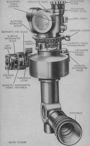
The panoramic telescope M12A7D was a modification of the M12A2 and shared the sight reticle with the latter. Improvements included the addition of a slipping azimuth scale with a locking screw, a nonslipping azimuth scale with an index door, a slipping azimuth micrometer scale with a locking nut, and a nonslipping left index. (Picture from TM 9-325 C8 105-mm Howitzer M2A1, Carriages M2A1 and M2A2, and Combat Vehicle Mounts M4 and M4A1.)
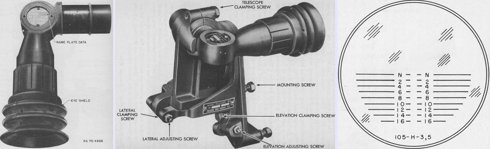
The elbow telescope M16 is seen isolated on the left and installed in the telescope mount M42 in the center, with its reticle pattern drawn on the right. The M16 was a 3x fixed-focus, prism-erecting instrument with a 90° elbow that allowed the user to face to the side while observing. It was used used in conjunction with the panoramic telescope M12A2 in a 2-man, 2-sight system when engaging moving targets with direct fire. Its reticle was composed of range lines only, marked in hundreds of yards, with "N" representing the normal line at the telescope's optical axis. (Picture from TM 9-731E Carriage, Motor, 105-mm Howitzer, M7.)
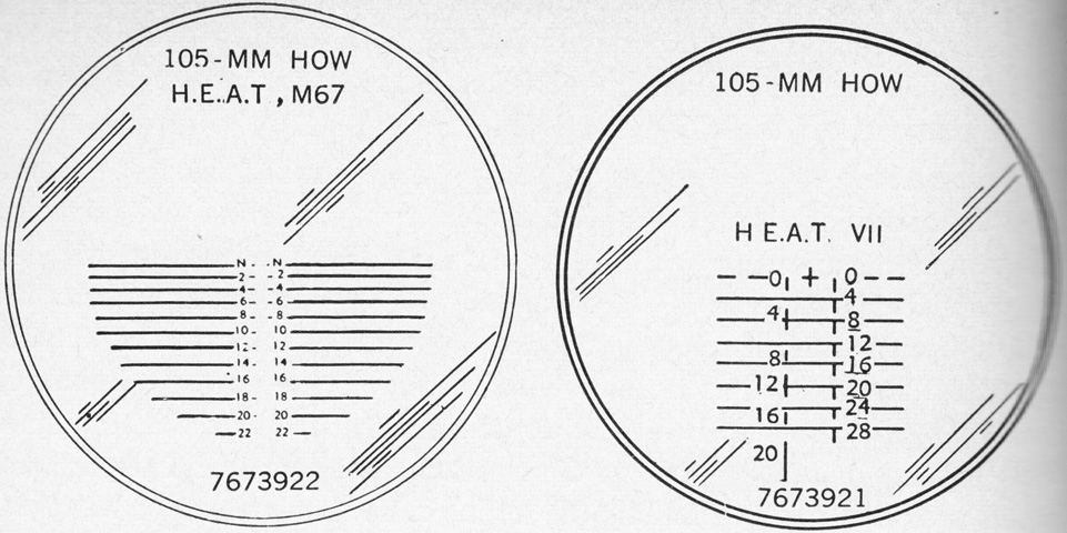
Sight reticles for the later elbow telescopes M16A1D and M16A1C are drawn above on the left and right, respectively. The M16A1D was graduated from 0 to 2,200 yards (2,010m) in 200-yard (180m) steps, with the 0-range (N) line passing through the optical axis. It was based on data from firing table 150-H-3 C8 with a muzzle velocity of 1,250ft/s (381m/s) minus a 0.4-mil jump. The M16A1C was designed for use with two types of ammunition. The right side was for the high-explosive shell M1 charge 7 at a 1,550ft/s (472m/s) muzzle velocity plus a 0.4-mil jump. The left side was for the HEAT shell M67 with a 1,250ft/s (381m/s) muzzle velocity plus a 0.7-mil jump. The cross at the 0 range line represented zero range and deflection for boresighting. (Picture from TM 9-325 C8 105-mm Howitzer M2A1, Carriages M2A1 and M2A2, and Combat Vehicle Mounts M4 and M4A1.)
Some of the instruments labeled above can be seen in this image of a museum vehicle.
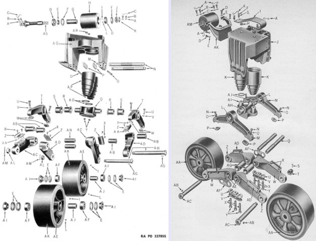
Exploded views of the the early (left) and heavy-duty (right) suspension bogies can be compared. The volute springs are P in the left diagram and K in the right. (Picture from ORD 7-8-9 SNL G-128.)
The heavy-duty bogies went through changes during production, including the shape of the track skid (C). Originally more of a semi-circular shape, it was later biased toward the front as seen here, and finally took the shape seen on the late bogie above. (Picture from ORD 7-8-9 SNL G-128.)
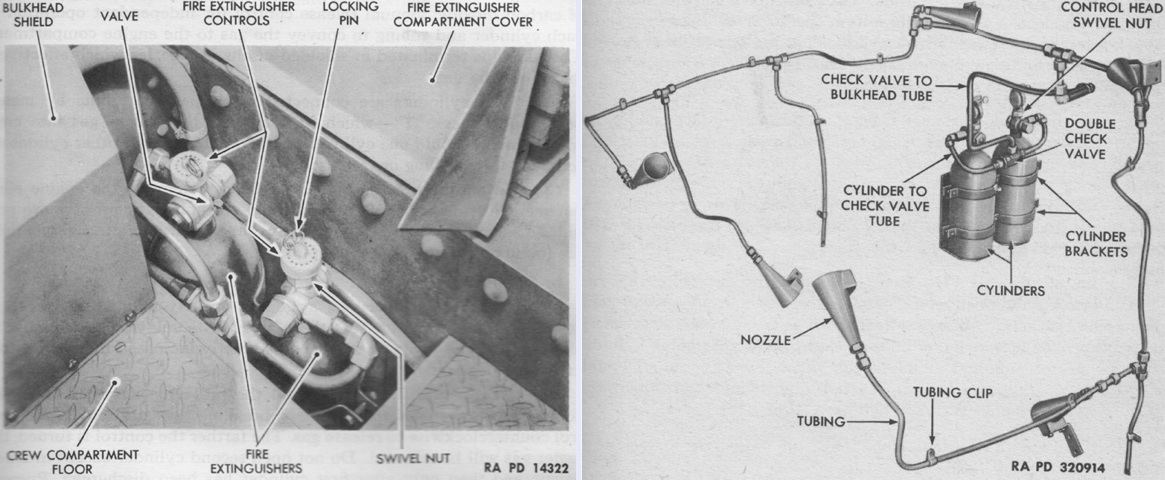
The fixed fire extinguisher system was used to suffocate fires in the engine compartment. Two 10lb (4.5kg) CO2 cylinders manufactured by Walter Kidde & Co., Inc., were installed in the left rear corner of the crew compartment under a hinged cover. Six discharge nozzles were spread throughout the engine compartment. The cylinders were operated manually via their control heads, and they were to be actuated one at a time: the second cylinder was intended to protect against the outbreak of a second fire. An early type is shown installed on the left, with valves that were actuated by turning the control handle counterclockwise. The tubing and discharge nozzles are diagrammed on the right along with late-type cylinders, with valves that were actuated by pushing the control handles downward. (Picture from TM 9-731E 105-mm Howitzer Motor Carriage M7 and TM 9-731E Carriage, Motor, 105-mm Howitzer, M7.)
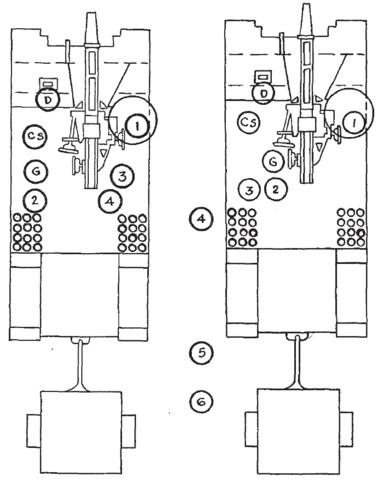
Crew positions are show here mounted (left) and ready for action (right). (Picture from FM 17-63 Service of the Piece, 105-mm Howitzer, Self-Propelled.)
Frontally, there was little to differentiate an M7B1 from an M7, but the rear of the former shared a common design with the medium tank M4A3. Tool stowage was moved to the larger hull rear plate since the engine deck was composed of opening louvres. (Picture from ORD 9 SNL G-199 List of All Service Parts of Carriage, Motor, 105-mm Howitzer M7B1.)

The armored flap behind the machine gun is folded down on this machine, and stowage baskets are installed atop the stowage boxes at the rear, in which are blanket rolls for the 7-man crew. Note the length of the hull visible behind the stowage baskets and above the idler wheel: the rear hull of the M7B1 sloped downward for a longer distance compared to that of the M7. (Picture from ORD 9 SNL G-199 List of All Service Parts of Carriage, Motor, 105-mm Howitzer M7B1.)

The longer rear hull is apparent from this rear ¾ view. The taillights are installed atop instead of on each side of the rear hull. Extended end connectors have been fitted to the tracks to increase their width and decrease ground pressure. (Picture from ORD 9 SNL G-199 List of All Service Parts of Carriage, Motor, 105-mm Howitzer M7B1.)

The arrangement of the fighting compartment was essentially the same as late-production M7s, where extra ammunition stowage replaced seats for four of the crew. The wide, louvred engine compartment doors on the rear deck are obvious, and just behind the fighting compartment can be seen an engine coolant filler cap in the center with a fuel filler cap to each side. (Picture from ORD 9 SNL G-199 List of All Service Parts of Carriage, Motor, 105-mm Howitzer M7B1.)
This cross-section illustrates the lower propeller shaft connection of the GAA engine, as well as the cooling radiator behind the engine necessitating the longer hull rear. (Picture from ORD 9 SNL G-199 List of All Service Parts of Carriage, Motor, 105-mm Howitzer M7B1.)
Although labeled as an M7, the longer rear hull and taillight visible behind the stowage basket indicate this machine is powered by the GAA engine.
This rear view establishes that this vehicle is derived from the M4A3 Sherman. The rear plate dips below the sponson line, the rear hull extends over the fenders behind the stowage boxes, and the exhaust deflector grid can be seen below the rear plate. The rear stowage boxes and baskets are visible, as are handles on the side of the hull. Attachment points for various tools are welded to the rear plate.
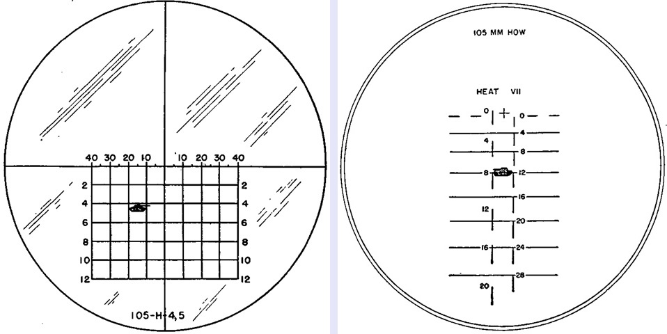
The reticle pattern for the panoramic telescope M12A7 is sketched on the left. It was similar to that of the M12A2, except that charges 4 and 5 were used. Drawn on the right, the elbow telescope M16A1C used an antitank pattern reticle, with graduations on the right side for the 105mm HE shell M1 using charge VII, and graduations on the left for the 105mm HEAT shell M67. In the sketches, a tank is being engaged with 15 mils lead with the M12A7 and at 800 yards (730m) range with a HEAT shell with the M16A1C. (Picture from FM 6-74 105-mm Howitzer M2A1 on Motor Carriage M7B1 and M7B2.)
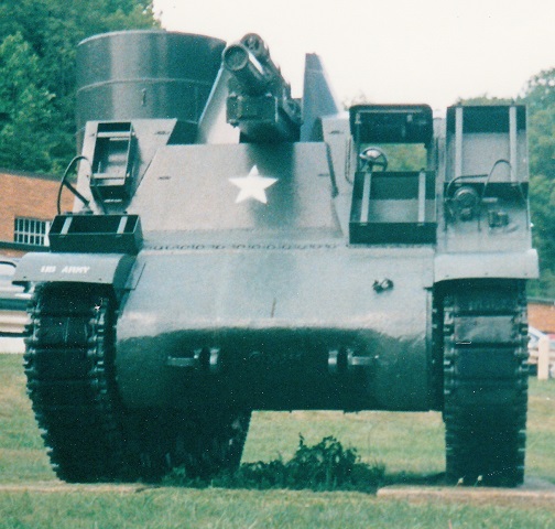
Compared with the M7B1 above, it is easy to see how this M7B2's howitzer has been raised, resulting in more elevation. The machine gun pulpit has had another section added to ensure a complete field of fire over the howitzer.
The modifications almost doubled the available howitzer elevation, from +35° to +65°.
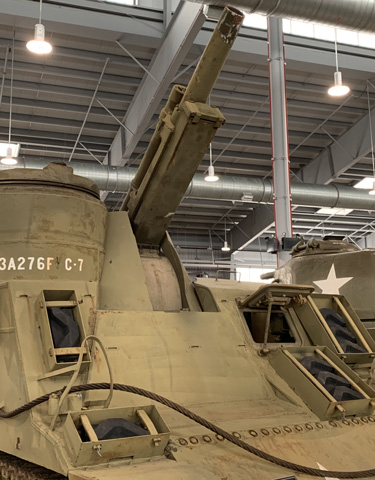
This side view provides a better view of the raised MG position. The folding armor flaps can also be seen behind the MG pulpit, above the side hull handles.
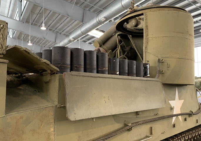
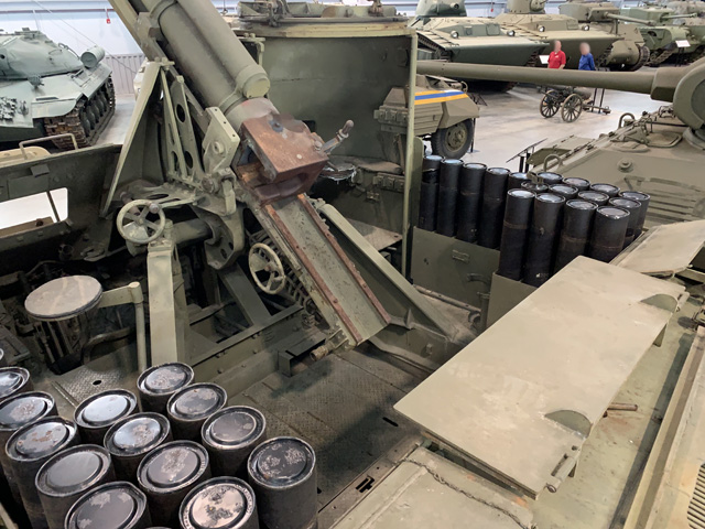
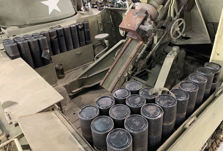
The utility of the additional flaps of armor is illustrated here, with howitzer ammunition tubes stowed in the motor carriage.
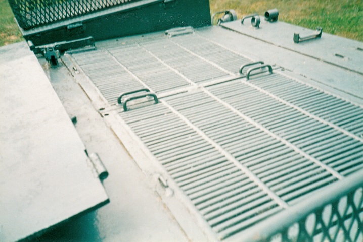
Like the medium tank M4A3 from which it was derived, the engine grill doors on this M7B2 run totally across the rear deck. The rear hinged armor plate is folded down, and is visible to the left in the picture.
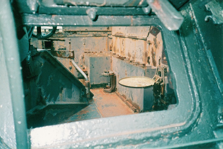
The driver's door is open on this vehicle, and this is a view through it into the interior. One circular seat for a member of the gun crew remains on the vehicle's left, and the mount for a portable fire extinguisher is visible in the left rear corner of the fighting compartment. One hundred-five millimeter ammunition racks line the hull sides, and the howitzer mount can be seen to the driver's right.
An overview of the front of the interior is provided in this image. The driver was at the front left, and sat lower than the level of the fighting compartment floor. A seat has been installed to the left of the howitzer mount.
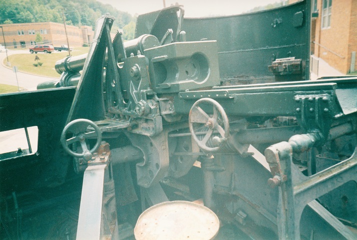
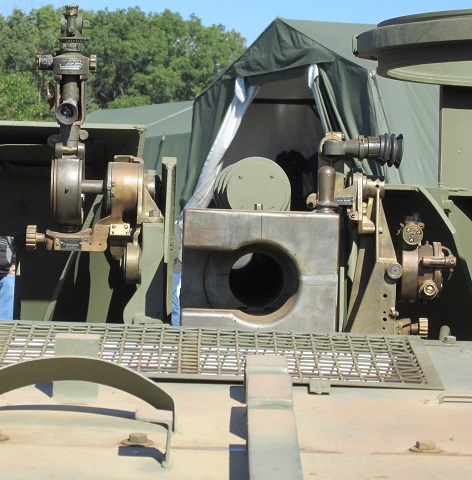
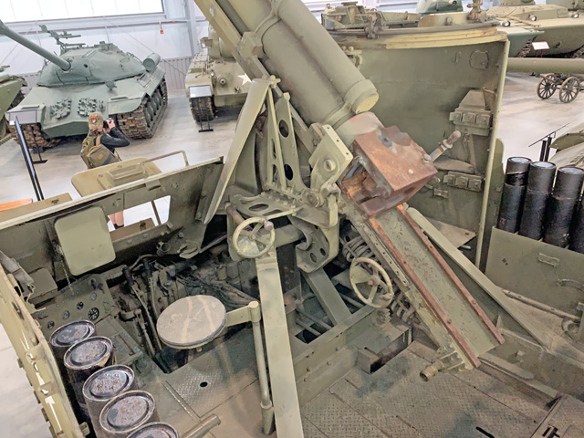
The 105mm howitzer M2A1 was mounted in the M7B2 by sticking the top half of the standard field carriage in the fighting compartment. The breech handle can be seen sticking up above the front of the breech. The handwheel to the front was for azimuth, and the elevation handwheel is to the rear. The howitzer shield can be seen on either side of the ordnance's barrel. The open driver's door is visible to the howitzer's left, and the inside of the machine gun position is visible to the right.
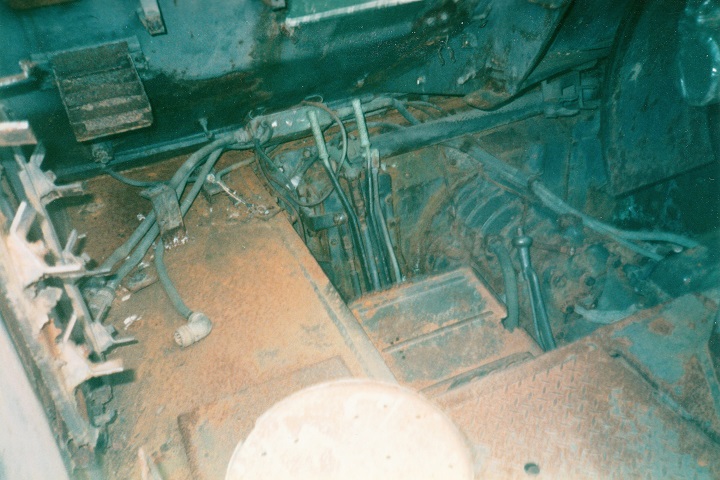
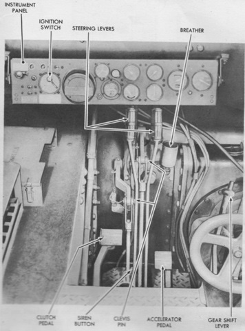
The M7B2 used driving controls common to the M4A3 tank, and they are illustrated here. The steering levers are in front of the driver's seat, and the gearshift lever is to the driver's right. The transmission itself is visible beside the driver's position.
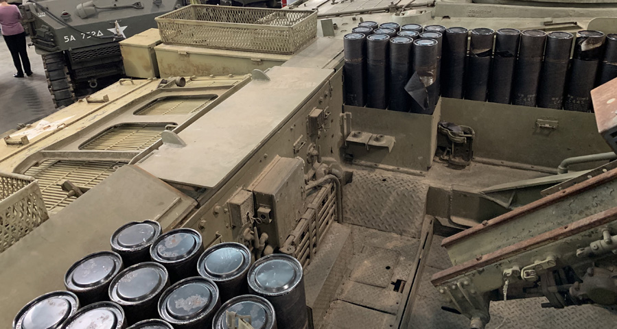
The fighting compartment is seen from the left rear. The additional ammunition racks compared to earlier motor carriages reduced the available space for crew seating.
The stowage bracket for a portable fire extinguisher is visible in the corner formed by the ammunition racks on the opposite side of the vehicle.
The rear of the fighting compartment and the engine compartment bulkhead are seen in this image.
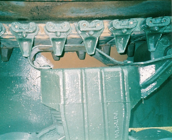
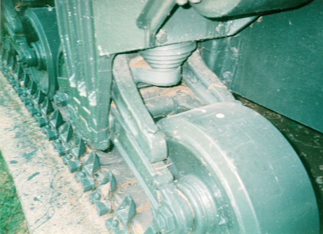
The heavy-duty suspension bogies carried over from the medium tanks M3 and M4 had both track return rollers and track skids. The skid design changed with modifications to the bogie, and this vehicle is equipped with the final design. Since the front of the track skid makes a loop and runs to the rear before it reaches the bogie frame, it indicates that the this bogie has its trunnion centers raised from earlier types, which improved spring stability. The front volute spring can also be seen.
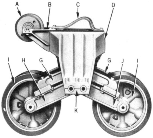
The innards of a vertical volute spring suspension bogie are illustrated here. The support bracket for the track return roller is visible at the top, and one of the volute springs can be seen in the center of the picture. Rubbing plates were positioned between the ends of the top lever and wheel arm, and the rubbing plate retaining screw can be seen at the end of the top lever.
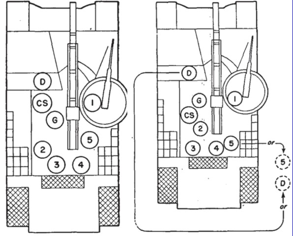
Postwar, another cannoneer was added to the vehicle. He is number 5 in these images. (Picture from FM 6-74 105-mm Howitzer M2A1 on Motor Carriage M7B1 and M7B2.)
