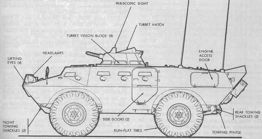
Light Armored Car M706.

A side view of an early production vehicle is sketched here. Note the number of vision blocks and firing ports in the side and the flat contour of the drivers' hatches. (Picture from TM 9-2320-245-10.)
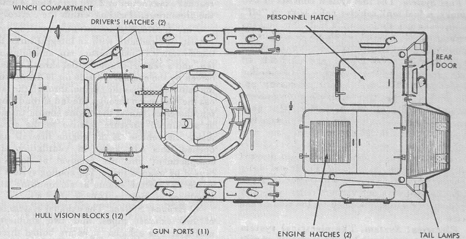
The top of an early car is shown here, with the plain air intake grille in the rear engine hatch. (Picture from TM 9-2320-245-10.)
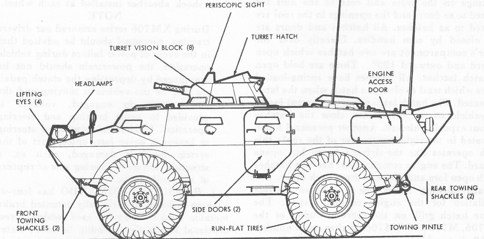
This later-production M706 features the deleted vision block and firing port forward of the side door, the anti-Molotov cocktail shield above the engine air intake grille, and drivers' hatches with a raised contour. (Picture from TM 9-2320-245-10.)
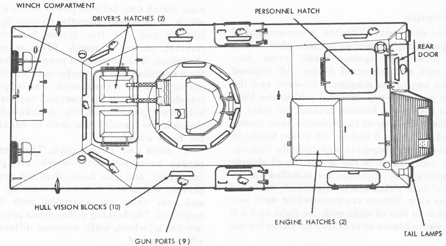
The top of a late car is illustrated. (Picture from TM 9-2320-245-10.)
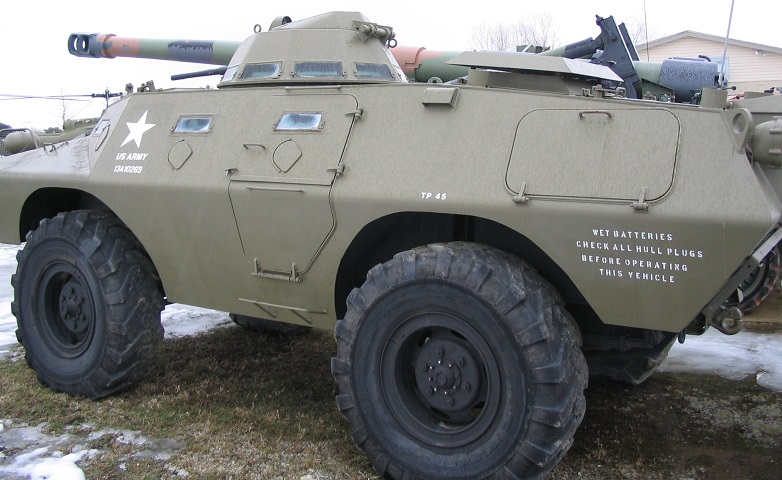
This is a later-production V-100, or an M706, as evidenced by features such as the engine compartment access hatch on the rear left side, the cover over the engine air intake grille on the vehicle roof, a single vision block and firing port in front of the two-part side door, and the circular wheel cutouts instead of the earlier angled cutouts. The turret had a single top hatch and vision blocks around its base.
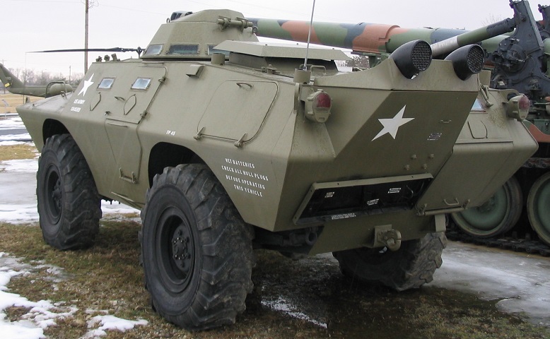
The extension to the exhaust housing can be seen on the hull's left rear corner, and the rear door can be glimpsed on the opposite side of the vehicle. A towing pintle is mounted between the rear wheels.
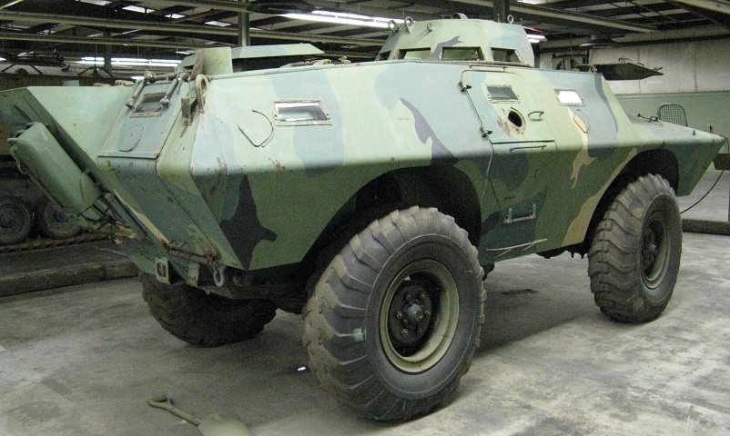
The rear door with its vision block and firing port is better shown better in this image. This door is also two-part, with the upper and lower halves both opening outward. The vision block and firing port in the right rear corner can also be seen. The turret hatch is missing from this vehicle.
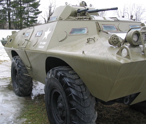
The offset placement of the turret armament can be seen here. The front vision blocks and firing ports in the front and forward sides are also shown.
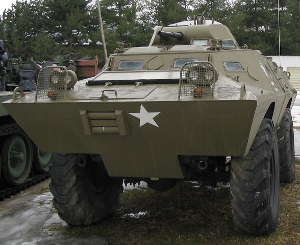
The location of the vehicle's winch can be discerned here, with the fairleads in the lower front hull and access hatch in the upper front slope. The front armor continues down between the wheels to help prevent the front differential from fouling on obstacles. The raised contour of the front roof hatches can also be seen in this picture.
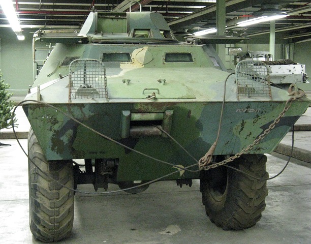
This vehicle's winch has a line ready for deployment, and the front roof hatches are open. The turret periscope guard can be seen on its roof, but the machine gun mount is missing.
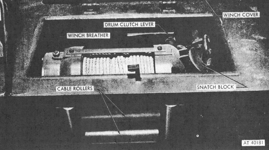
The cover of the winch has been raised in this picture. It was an hydraulically-powered, worm-gear, jaw-clutch, drum-type winch that was provided with a snatch block to double the line pull when required. After pulling up on the PTO knob to the right rear of the driver's seat, the drum clutch lever was used to engage or disengage the winch drum. The winch control lever near the driver's position was used to change the winch direction. Once the drum clutch was engaged, the accelerator pedal was used to achieve the desired line speed. (Picture from TM 9-2320-245-10.)
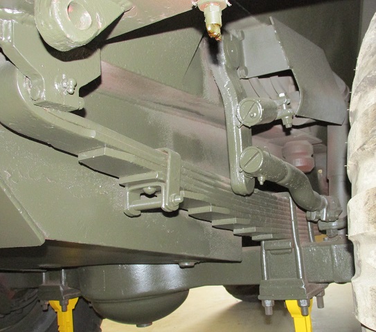
Details of the installation of the front suspension can be seen here.
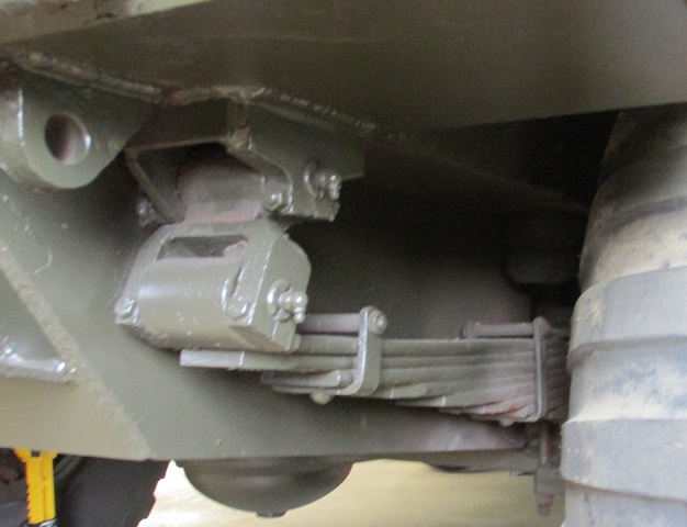
A similar image is provided of the rear leaf springs.
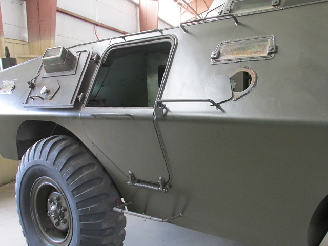
The upper half of the right-side door is open. The vision block and firing port can be seen; the firing port ahead of the door is open.
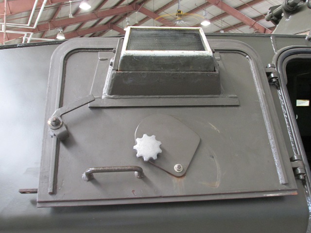
Details of the interior of the upper door are provided here.
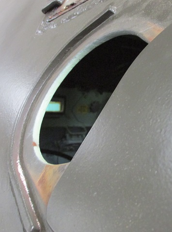
The thickness of the side armor can be gleaned by looking through the open firing port.
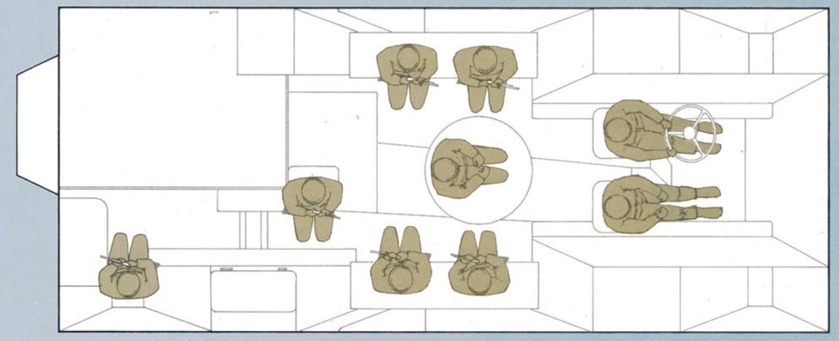
This diagram illustrates the seating positions in a vehicle equipped with a rotating turret. (Picture from Commando: Combat Proved Multi Mission Armored Vehicle.)
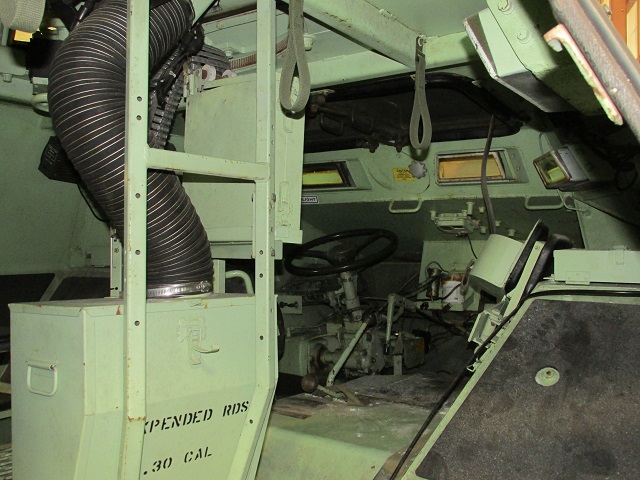
This view is looking forward into the cabin from the right-side door. The driver's controls, vision blocks, and hatches can be seen to the front, and a chute to route expended machine gun cases into a bin is visible to the left of the image.
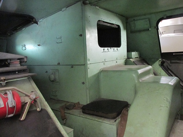
The engine housing at the vehicle's left rear is shown here. A cushion and seat belt can be seen across the walkway that leads to the rear door.
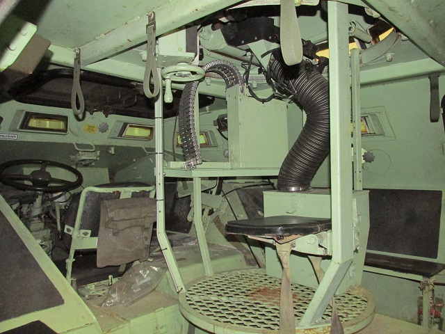
The opposite side of the cabin is shown here. Ammunition feeding and collection chutes for the expended cases can be seen leading up into the turret, and a bench seat is mounted on the opposite wall.
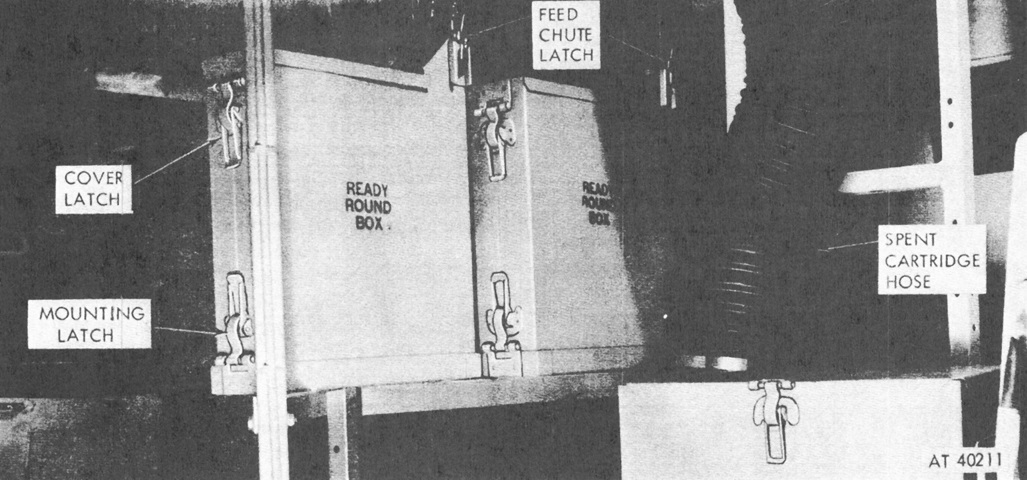
Both ammunition boxes are shown mounted.(Picture from TM 9-2320-245-10.)
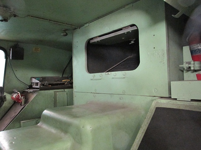
The engine compartment dominates the left rear corner, and a radio rack can be seen on the shelf on the other side of the vehicle. Two of the three fire extinguishers with which the vehicle was equipped are also in the frame. On the right of the image, on top of the left rear wheel well, a 5lb (2.3kg) CO2 extinguisher was routed to the engine compartment to smother fires there. Two portable 2¾lb (1.25kg) Freon extinguishers were also carried: one on the forward plate of the right rear wheel well as shown, and a second on the right front wall of the crew compartment.
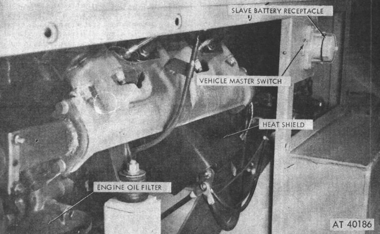
The wall has been removed from the lower engine compartment. The engine was a 361in³ (5.92L), overhead valve type with a 7.8:1 compression ratio and a firing order of 1-8-4-3-6-5-7-2. Governed speed was 4,000rpm, and idle was 600rpm. Two 12-volt batteries were mounted to the left of the engine, connected in series to form a 24-volt system. (Picture from TM 9-2320-245-10.)
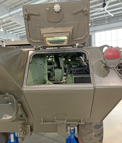
The upper half of the rear door is open on this vehicle, revealing the vision block, door latches, and firing port cover and control. Springs helped ease the effort required to manipulate the doors.
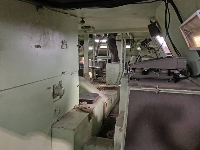
This image is looking into the open rear door. The radio rack is on the shelf to the right, and the narrowness of the tunnel leading to the rear door can be appreciated. The right rear hull vision block is at the very right of the frame.
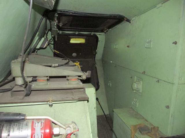
The tunnel leading to the rear door is shown here from the opposite angle. The roof hatch and rear door can be seen in their darker shade of paint, and more details of the radio rack are provided.
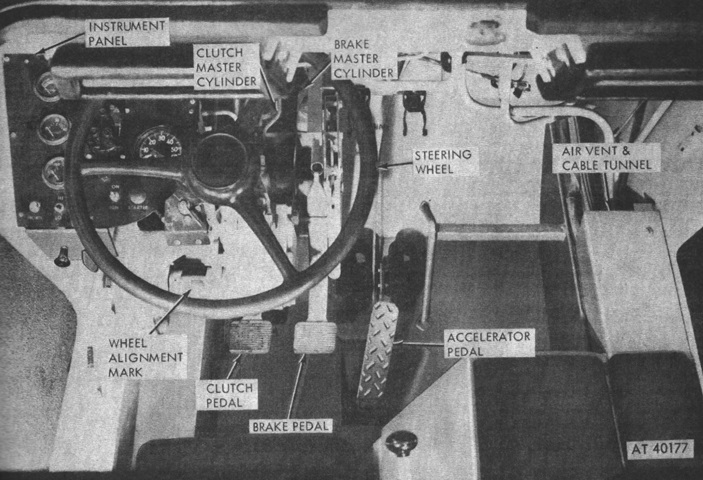
The driver's controls are labeled in this image. (Picture from TM 9-2320-245-10.)
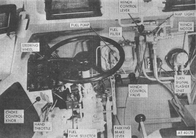
Additional controls and fittings around the driver are shown here. (Picture from TM 9-2320-245-10.)
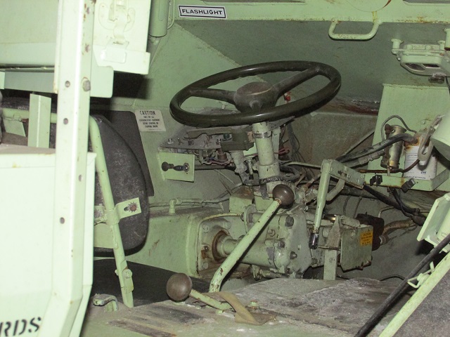
This picture shows a closer view of the driver's position. The steering wheel is obvious, and the instrument panel is to the steering wheel's front left, with the black choke control knob emerging from underneath toward the driver. The downward-pointing L-shaped lever to the driver's front right is the parking brake lever, and the gear shift lever faces forward to the right of the driver's seat. The lever with the kinked shaft closest to the camera is the 4-wheel drive shift lever. The fuel filter and fuel pump can be seen to the front of the driver's compartment, and a map light is mounted above these.
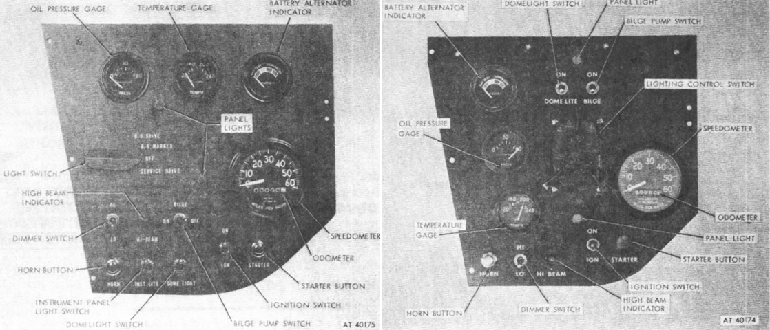
Early (left) and late (right) instrument panels can be compared. (Picture from TM 9-2320-245-10.)
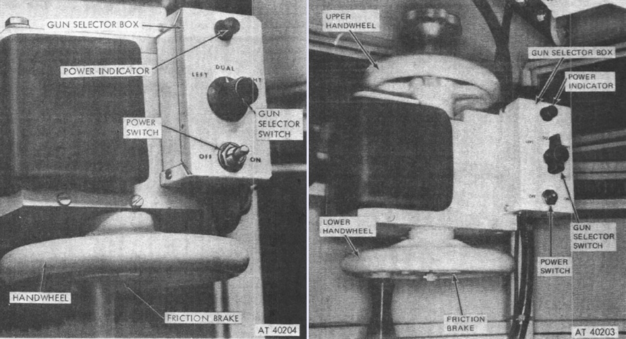
Early-production turret controls are highlighted in the left image. The handwheel was for turret traverse, while elevation was accomplished with a handle extending from the gun cradle; the electrical trigger button was mounted on the end of the elevation handle. The power switch activated the firing circuit, and the gun selector switch had positions for selecting the left, right, or both guns. Modifications made to the turret controls during the production run can be gleaned from the picture on the right of a later machine. (Picture from TM 9-2320-245-10.)
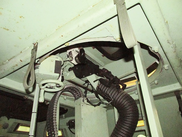
The turret traverse handwheel, machine gun mount, and sighting periscope can be seen as we look up into the turret. Each complete turn of the traverse handwheel rotated the turret 10.75°. Handle loops for the passengers are hung from the ceiling.
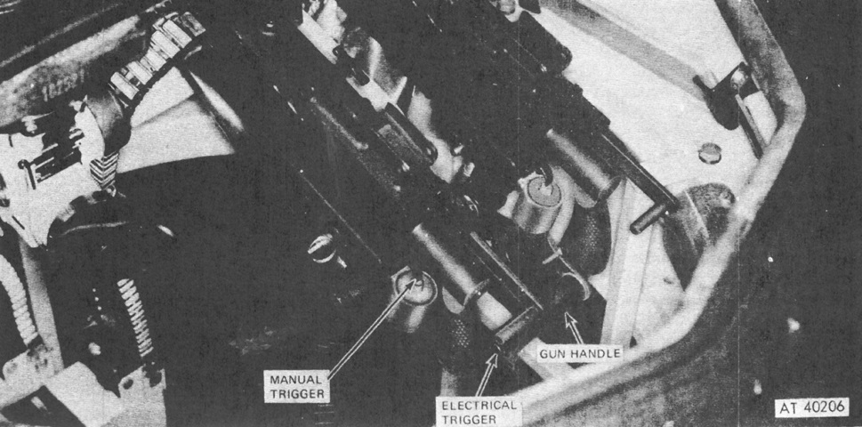
The gun elevation handle for the early production gun mount is shown here. The manual trigger allowed the guns to fire in the absence of electrical power to the turret. (Picture from TM 9-2320-245-10.)
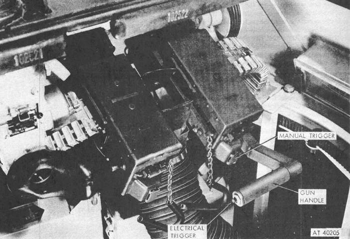
This picture is of the late-production elevation handle. (Picture from TM 9-2320-245-10.)
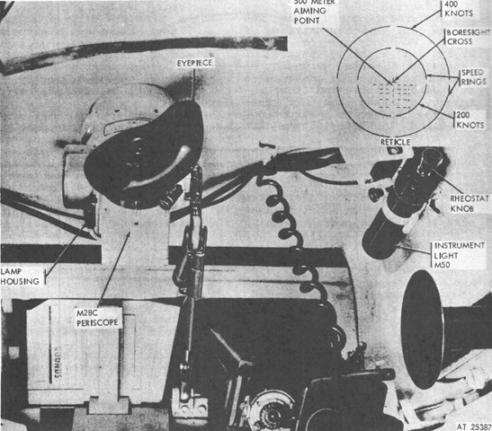
The front of the machine gun turret is shown here, with the periscope M28C installed. Its sighting reticle is detailed in the inset at the upper right. (Picture from TM 9-2320-245-10.)
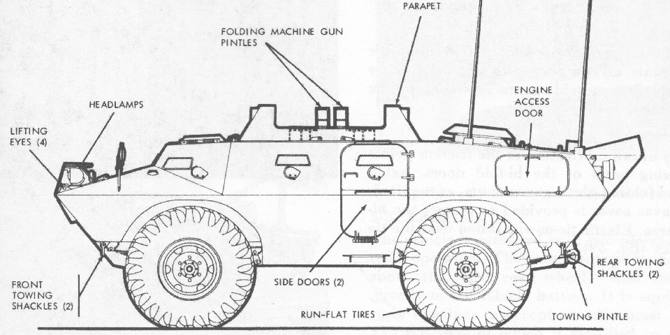
The replacement of the machine gun turret with an armored parapet closed with folding doors marked this model of the vehicle. (Picture from TM 9-2320-245-10.)
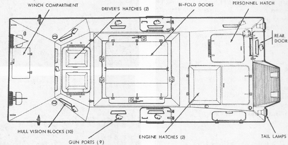
The folding doors are visible in this top-down view. (Picture from TM 9-2320-245-10.)
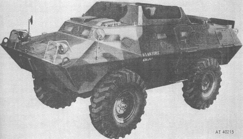
The bi-folding doors are open on this machine. (Picture from TM 9-2320-245-10.)
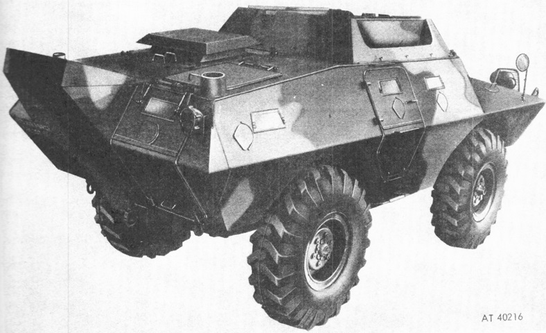
The parapet can be seen here from the rear. (Picture from TM 9-2320-245-10.)
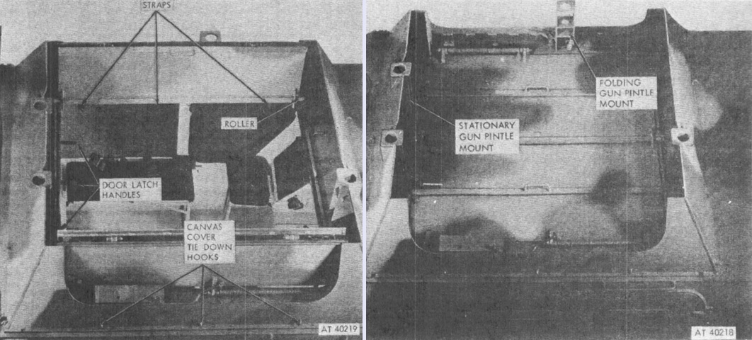
The bi-folding roof doors are shown here in the open (left) and closed (right) positions. The doors could be opened or closed from inside using the hand straps. (Picture from TM 9-2320-245-10.)
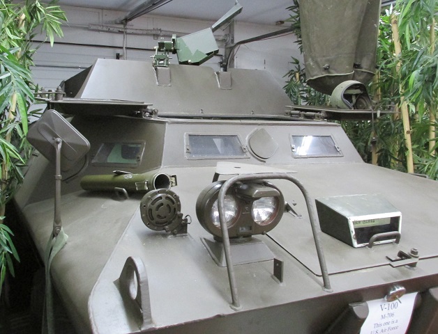
Both drivers' hatches are open on this car, and a machine gun mount is present on the forward wall of the parapet.
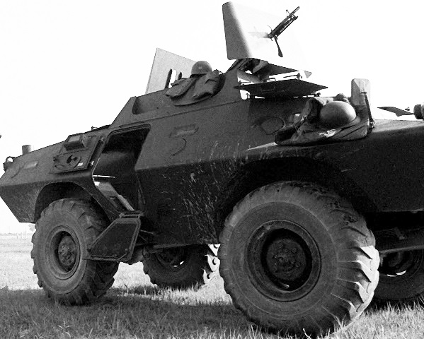
The machine guns on this vehicle have shields protecting the gunners. Note the operation of the open side door and interior details of the vision block and firing port. (Picture taken 15 July 1977 by SSGT Mike Creen; available from the National Archives.)
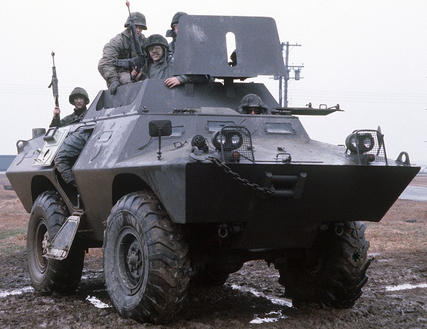
Another view of the XM706E2 (and a view of some poor trigger discipline) is provided here. These men were participating in Exercise Team Spirit '81. (Picture taken 1 Mar 1981 by MSGT Bert Mau; available from the National Archives.)
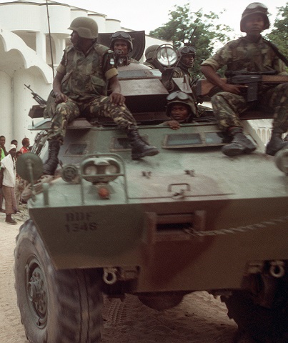
The driver of the V-150 was provided with a second vision block, and the front firing port was deleted. Note how the driver's vision blocks are angled outward from the hull in contrast to the earlier design. This vehicle is crewed by a Botswani task force searching for weapons during Operation Restore Hope. (Picture taken 25 January 1993 by PH1 R.J. Oriez; available from the National Archives.)
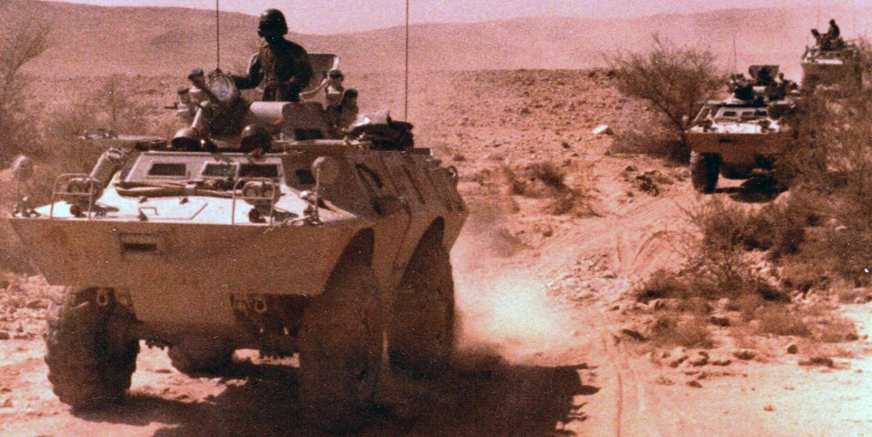
The front V-150 in this convoy is topped by a turret armed with a .50cal and .30cal MG, along with smoke grenades and a searchlight. The two angled vision blocks for the driver can be seen. (Picture courtesy InTTruder.)
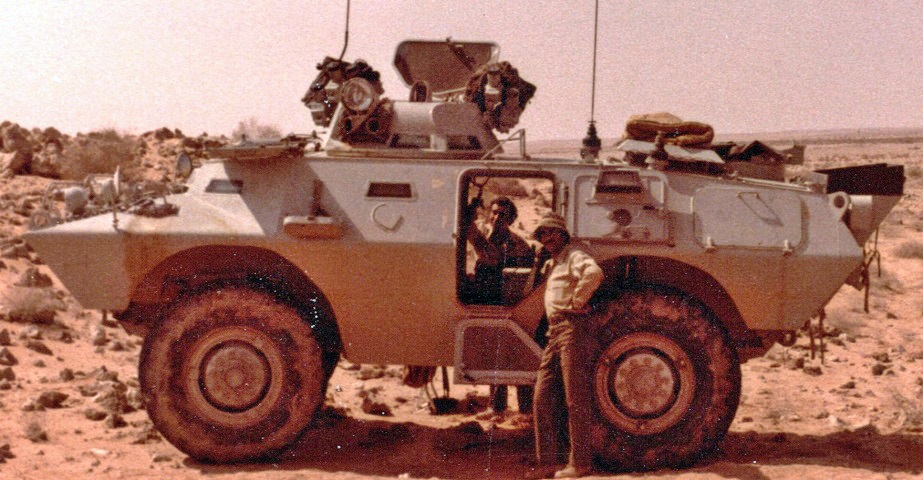
The hatches and side doors are open on this machine, and the armament's position offset to the turret's right side can be gleaned. (Picture courtesy InTTruder.)
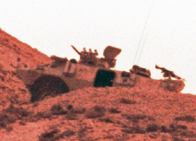
A further 7.62mm machine gun has been mounted at the rear roof hatch of this car. (Picture courtesy InTTruder.)