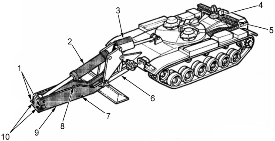
Armored Vehicle Launched Bridge M60A1.
The vehicle is shown here with the launcher extended and the bridge absent. 1. Pintles. 2. Tongue cylinder. 3. Overhead cylinder. 4. Holddown cylinder. 5. Bridge seat. 6. Boom and outrigger. 7. Guide pin. 8. Locking cylinder. 9. Tongue. 10. Ejection cylinders. (Picture from TM 5-5420-202-10.)
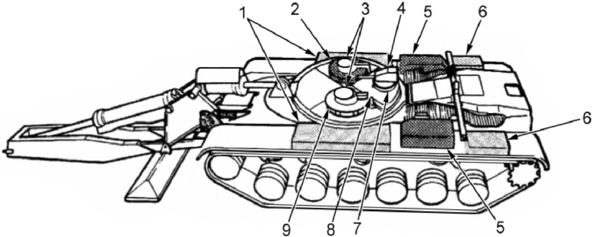
1. Front fender stowage boxes. 2. Commander's cupola. 3. Hatches. 4. Antenna mount. 5. Engine air cleaners. 6. Rear fender stowage boxes. 7. Ventilating blower cover. 8. Hydraulic oil reservoir. 9. Operator's cupola. (Picture from TM 5-5420-202-10.)
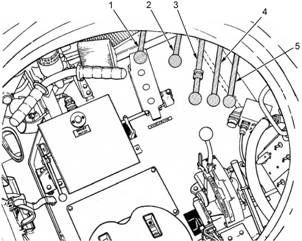
The operator's position is shown here. The steering T-bar to his front and the transmission selector to his right are visible but unlabeled in this figure. The controls for the various hydraulic cylinders are as follows: 1. Eject lever. 2. Lock lever. 3. Scissors lever. 4. Tongue lever. 5. Overhead lever. The perforated accelerator pedal can be seen underneath the eject lever, and the brake pedal is behind the right handgrip of the steering bar. (Picture from TM 5-5420-202-10.)
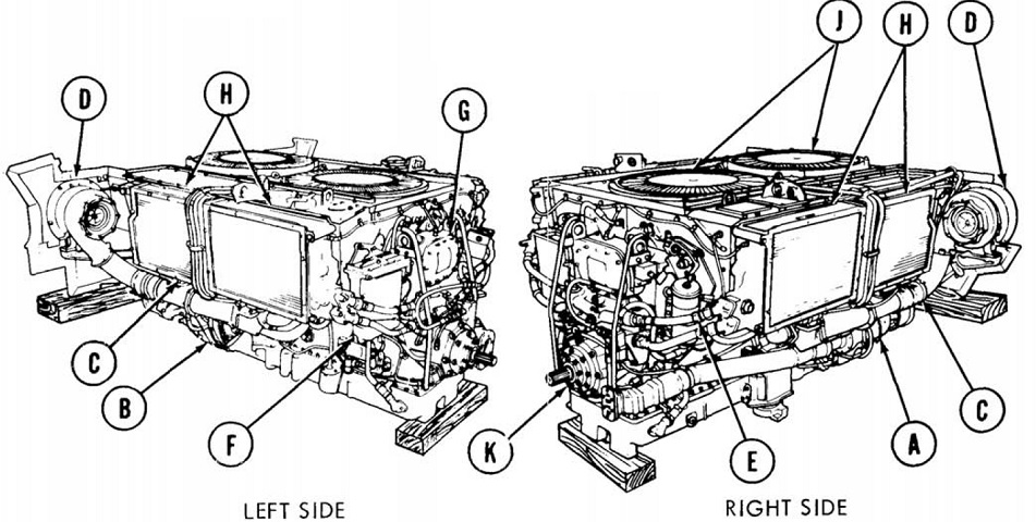
The engine is drawn here. The launcher hydraulic system pump was driven by the power takeoff. A. Air-cooled generator/Oil-cooled alternator (HEU). B. Starter. C. Manifold heater. D. Turbosupercharger. E. Fuel filter. F. Fuel/water separator. G. Oil filter. H. Oil cooler. J. Cooling fan. K. Power takeoff. (Picture from TM 5-5420-202-20-1.)
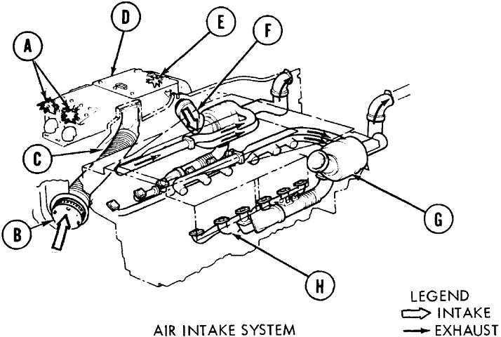
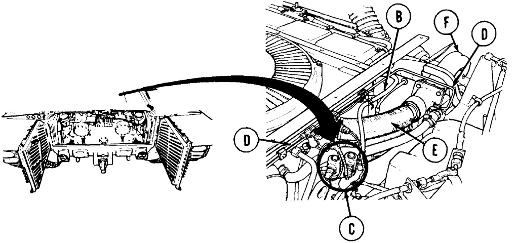
An armored top-loading air cleaner assembly is illustrated here. A. Air cleaner blower fans. B. Engine air intake. C. Air intake hose. D. Air cleaner. E. Dry-type filter unit. F. Air outlet hose assembly. G. Turbosupercharger. H. Air intake manifold. (Picture from TM 5-5420-202-20-1.)
The smoke generator, controlled by a switch on the operator's master panel and powered through the air cleaner blower motor relay, injected fuel into the exhaust pipes, after which it passed through the turbosuperchargers and exited the vehicle as a dense, white cloud. B. Main fuel line. C. Fuel solenoid valves. D. Fuel output tubes. E. Exhaust pipe. F. Turbosupercharger. (Picture from TM 5-5420-202-20-1.)
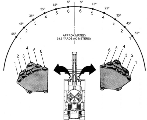
The firing pattern from the M239 smoke grenade launchers is diagrammed here. Two switches were provided for the operator to launch the grenades: the left button fired grenades 1, 3, and 5 in the left discharger and 6, 4, and 2 in the right discharger. The right button fired the opposite grenades, and pushing both buttons fired a complete salvo. (Picture from TM 5-5420-202-10.)
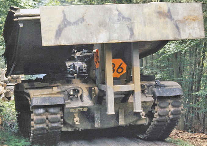
The vehicle with its stowed bridge presents an imposing view while moving down a forest trail during REFORGER '83. (Picture taken 21 Sep 1983 by SSG Ernest Sealing; available from the National Archives.)
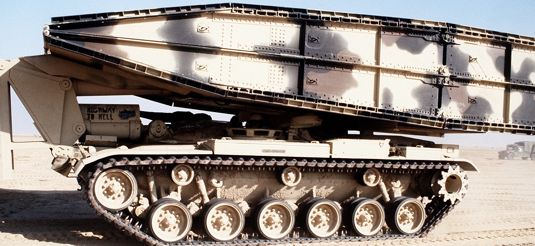
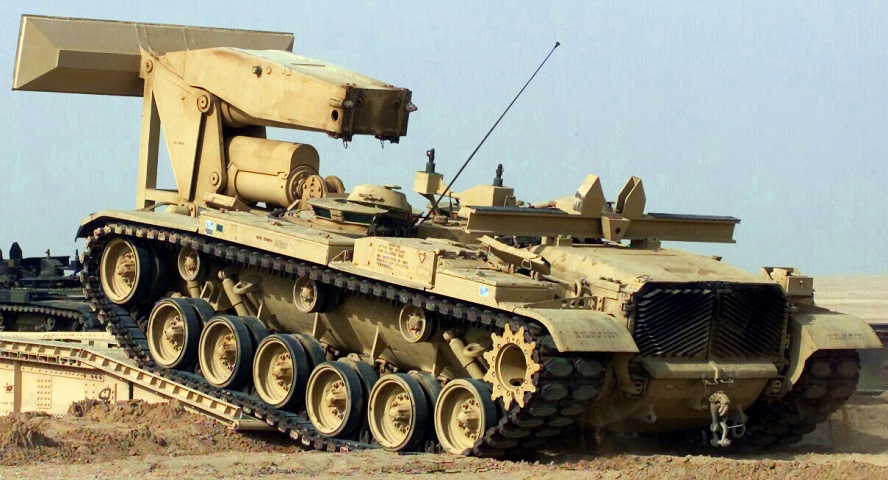
The positioning of the stowed bridge can be better seen in this side view. "Highway to Hell" belonged to the 2nd Marine Expeditionary Unit and was in Saudi Arabia awaiting its part in Operation Desert Storm. (Picture taken 24 Feb 1991 by J.R. Ruark; available from the National Archives.)
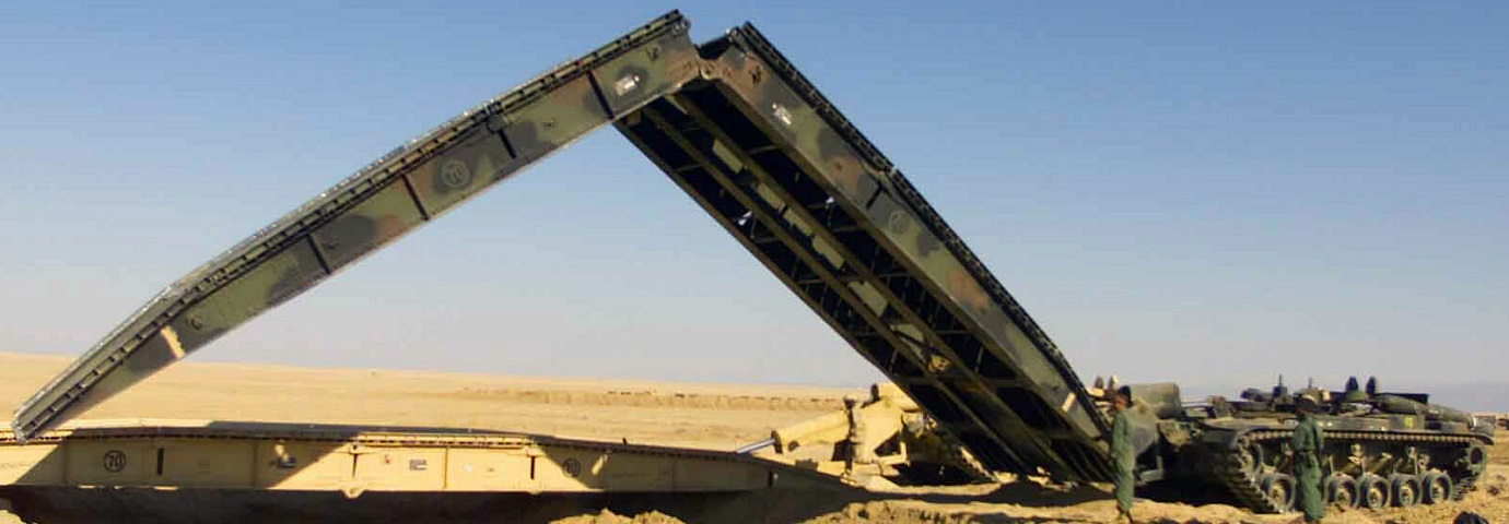
The bridge of this vehicle, belonging to the USMC 1st Tank Battalion, is in the process of being unfolded over a dry wash. (Picture taken 17 Feb 2003 by LCPL Kevin C. Quihuis, Jr.; available from the National Archives.)
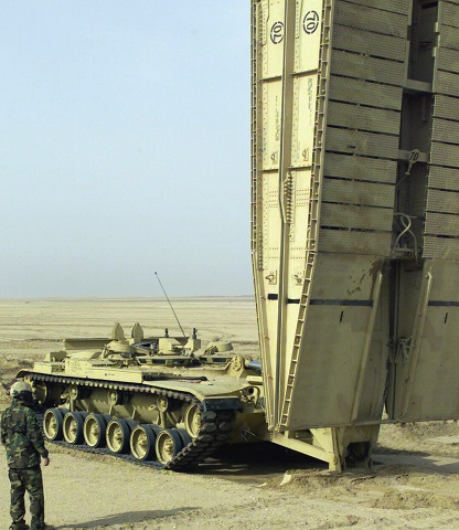
This Marine 1st Tank Battalion vehicle is seen here recovering its bridge during training during Operation Enduring Freedom. (Picture taken 8 Feb 2003 by SGT Paul L. Anstine II; available from the National Archives.)
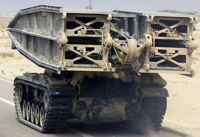
Details of the bridge hinge mechanism can be seen here. Also note the bulge in the hull under the engine exhaust grilles and the extended bottom lip of the grilles; this hull was originally an M60A2 equipped with the closed-breech scavenging system (CBSS). This vehicle belonged to C Company of the Marine Corps's 1st Tank Battalion and was traveling route Tampa near the Jalibah Airfield in Iraq during Operation Iraqi Freedom. (Picture taken 24 Mar 2003 by SGT Paul L. Anstine II; available from the National Archives.)
This hull also was a CBSS-equipped M60A2, and it allows us a better view of the bridge launching and resting apparatus as it begins to cross the bridge it has just launched. This vehicle was from the Marines' 1st Tank Battalion and was practicing during Operation Enduring Freedom. (Picture taken 6 Feb 2003 by LCPL Kevin C. Quihuis, Jr.; available from the National Archives.)
