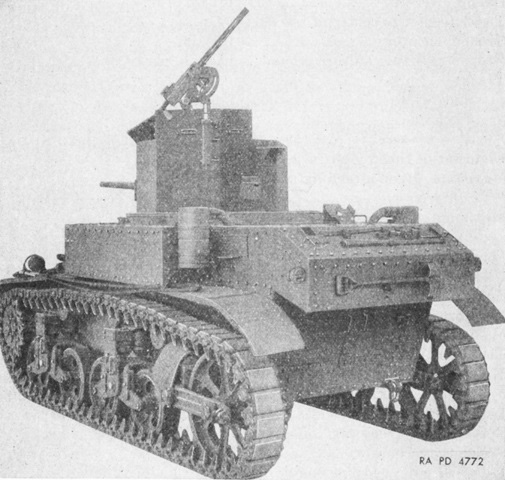
Light Tank M3 Stuart.
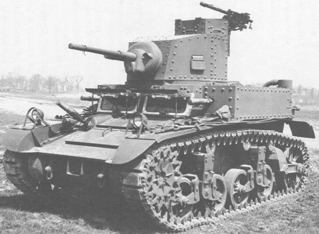
This is the first light tank M3 produced. The sponson machine guns are mounted in this tank, and the driver's viewing doors are open. There are windscreens with integral wipers fitted in front of the drivers; these would not be used in a combat area. (Picture from Tank Data, vol. 2.)
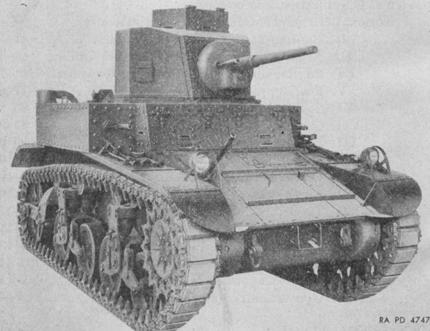
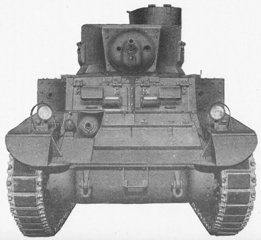
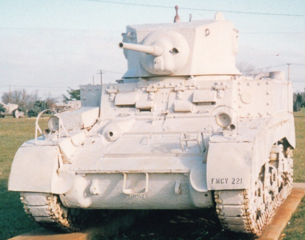
The drivers' doors are closed here. The turret pistol ports and drivers' doors were provided with peepholes. (Picture from TM 9-726 Light Tank M3.)
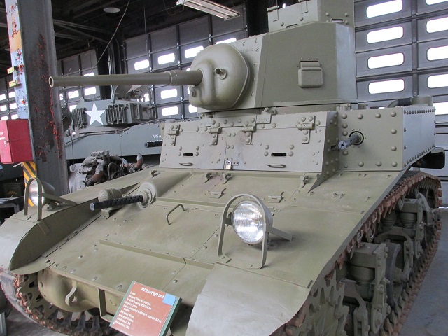
This machine also sports a welded turret, and is provided with peepholes in the cupola, turret pistol port doors, and drivers' doors.
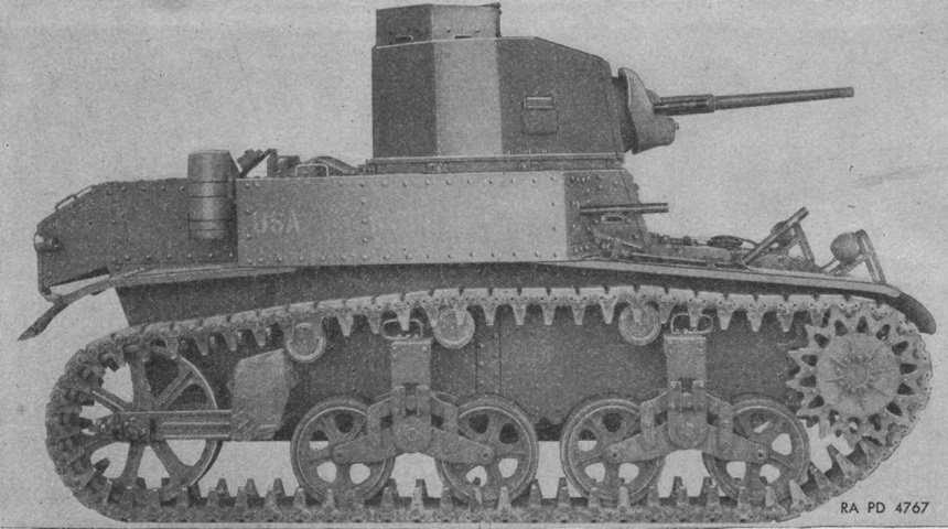
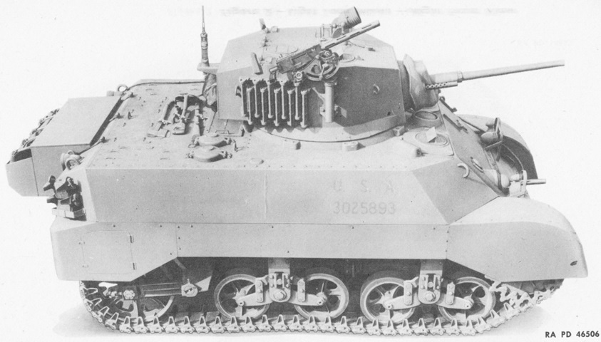
This tank is also fitted with the face-hardened welded turret. The sponson machine guns are easily seen from the side. (Picture from TM 9-726 Light Tank M3.)
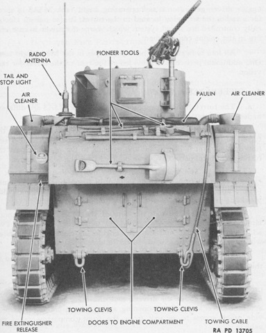
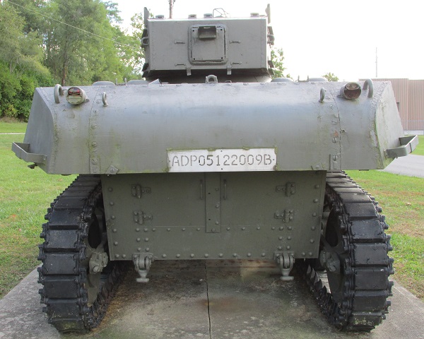
The rear of the tank is shown here; note the short pipes emanating from the air cleaners. The front-hinged cupola hatch is open, and pioneer tool stowage and an antenna mount can be seen on the rear deck. (Picture from TM 9-726 Light Tank M3.)
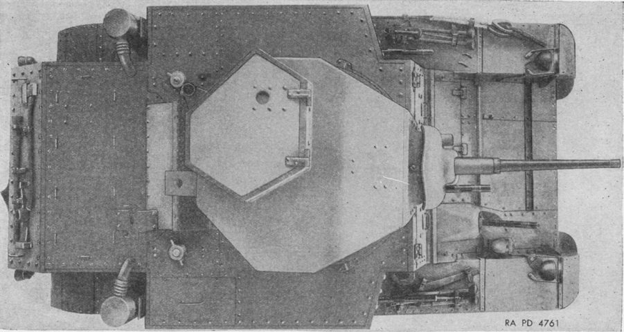
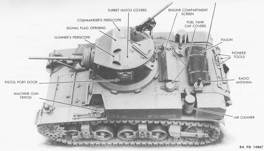
The asymmetrical nature of the octagonal turret and hexagonal commander's cupola can be seen in this top-down view. The filler caps for the two fuel tanks are visible behind the turret. (Picture from TM 9-726 Light Tank M3.)
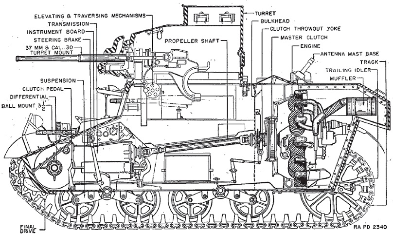
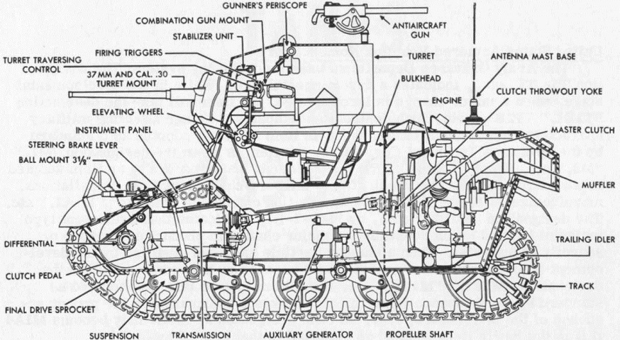
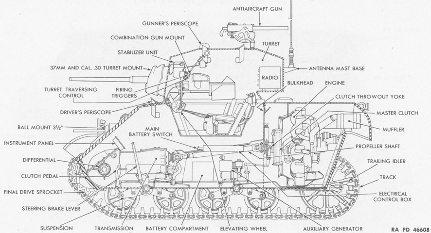
A cross-sectional view of the tank is shown here. Note the unlabeled sponson-mounted machine gun. (Picture from TM 9-726 Light Tank M3.)
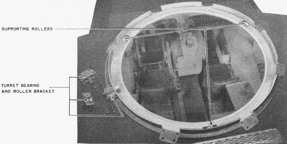
The turret ring rested on a trio of turret support rollers spaced 120° apart. The turret rotating mechanism was bolted to the turret, and the pinion of this mechanism was in constant mesh with the gear of the circular track. Lateral and vertical movement of the turret was prevented by bearings and rollers which contacted the side and upper surface, respectively, of the turret ring. The bearings and rollers were installed in eight brackets which were bolted to the hull at unevenly spaced intervals. (Picture from TM 9-726 Light Tank M3.)
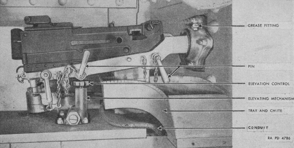
Details of the left sponson machine gun mount can be seen in this image. (Picture from TM 9-726 Light Tank M3.)
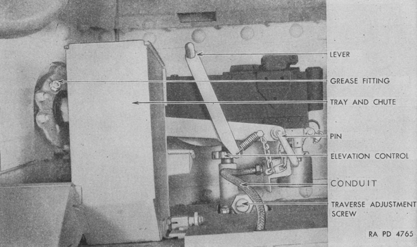
The right sponson machine gun is shown here. The sponson guns were fired by the driver via switches near the top of his steering levers, with the left and right levers controlling the left and right sponson machine guns, respectively. (Picture from TM 9-726 Light Tank M3.)
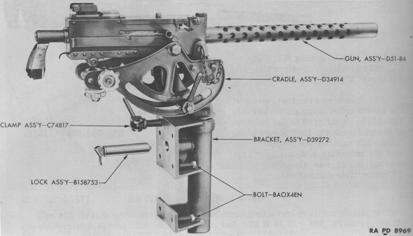
Parts of the elevator bracket mount M20 for the antiaircraft machine gun are labeled here. Initially, it provided 160° of traverse in the mount, but later M20s were capable of 360° traverse. The gun could of course be traversed through 360° with the turret. (Picture from Weapon Mounts for Secondary Armament.)
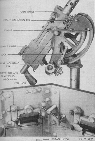
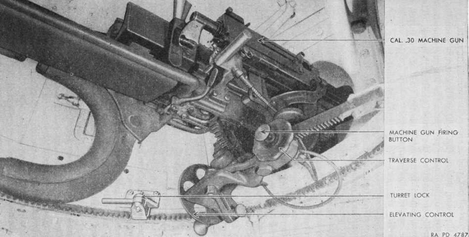
The antiaircraft machine gun is mounted and raised. The elevation lock was located on the machine gun cradle, while the traverse lock was inside the cupola itself. The traverse lock and pintle clamp both protruded through the upper mounting pad. (Picture from TM 9-726 Light Tank M3.)
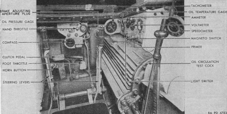
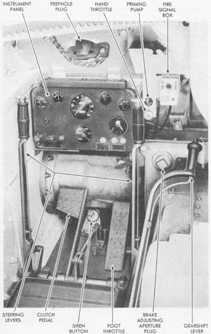
The driver's compartment and controls are pictured here. (Picture from TM 9-726 Light Tank M3.)
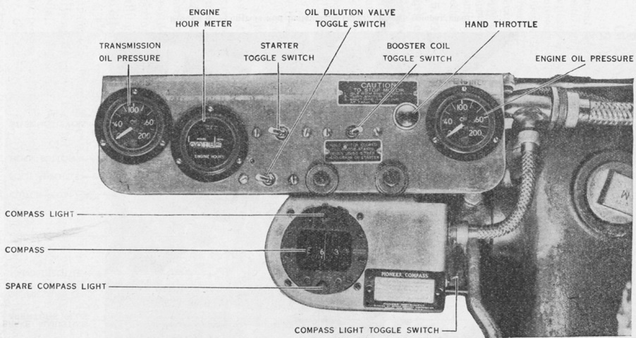
The driver's instruments were spread across two panels. The front panel is detailed here. (Picture from TM 9-726 Light Tank M3.)
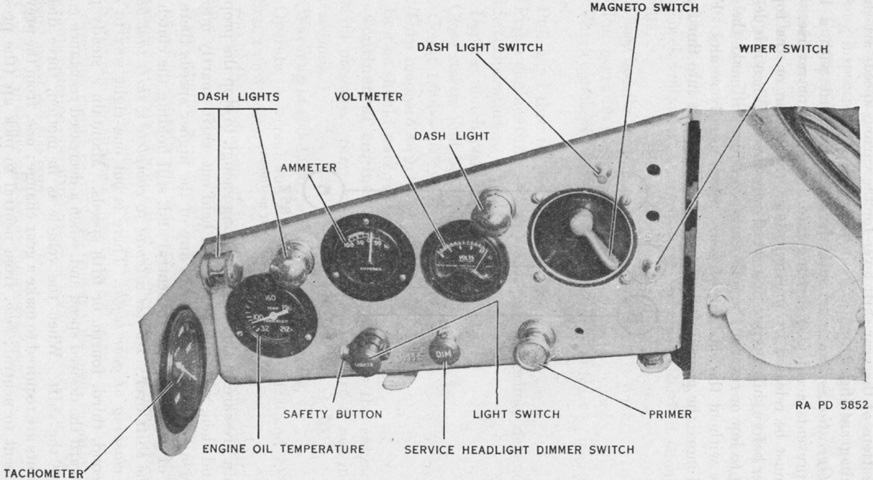
The second instrument panel was to the driver's right. (Picture from TM 9-726 Light Tank M3.)
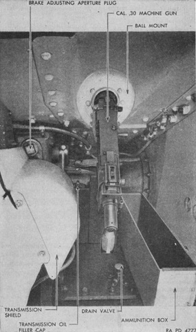
The assistant driver's 3.5" (8.9cm) machine gun mount is illustrated in this picture. (Picture from TM 9-726 Light Tank M3.)
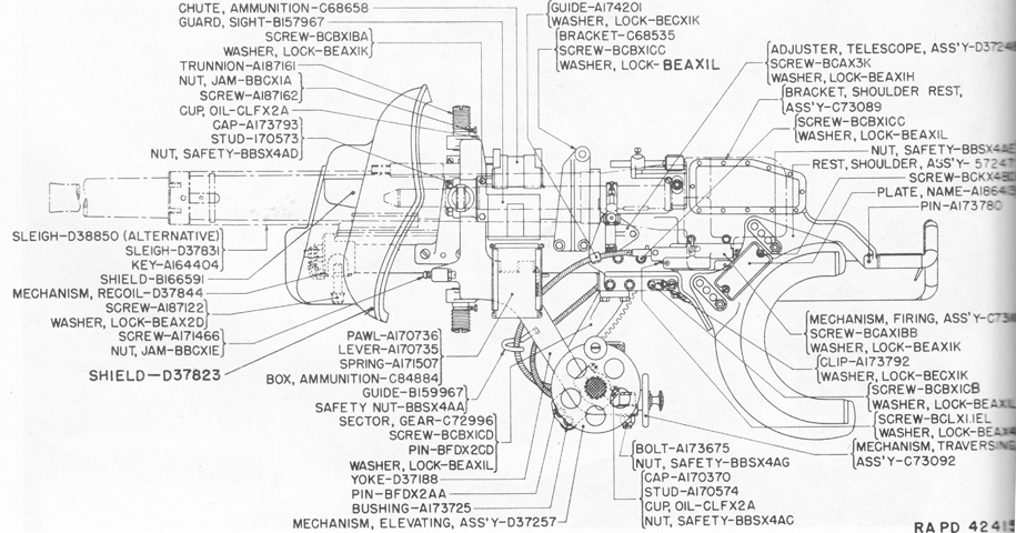
A cross-section of the combination gun mount M22 is sketched here. Compared to the combination gun mount M20 in the light tank M2A4, the recoil mechanism and sleigh were shortened, and the gun shield was modified to completely cover these items. (Picture from Weapon Mounts for Secondary Armament.)
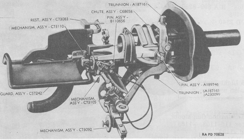
The gun mount is seen from the upper right with no weapons or sight present. The vertical trunnions that permitted in-mount traverse of the guns can be seen, as well as the projection from the front of the gun shield that protected the shorter sleigh for the 37mm gun. (Picture from Weapon Mounts for Secondary Armament.)
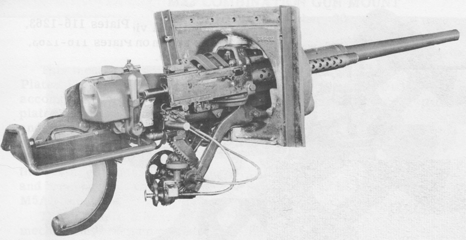
The 37mm gun and coaxial machine gun are mounted here, while the telescope is hidden on the other side of the 37mm gun. The interfacing of the vertical trunnions with their receptacles in the turret front plate can be seen. (Picture from Weapon Mounts for Secondary Armament.)
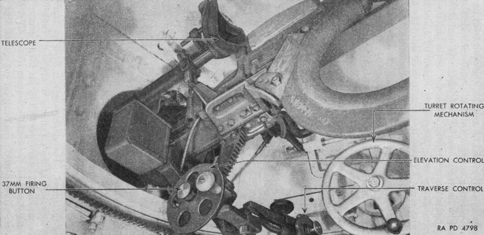
The combination gun mount M22 is seen here from the lower left. The semi-circular padded gunner's shoulder rest is at the upper right of the image; the gun mount could be disconnected from the elevation and traverse gears and the gunner could use his body via the shoulder rest to control the guns. Note that there is a traverse control handwheel in addition to a turret rotating handwheel. The traverse control was used to traverse the gun mount up to 10° in either direction independently of the turret. The commander would rotate the turret onto a rough bearing using the turret rotating mechanism, from which the gunner would then take over using his controls. The coaxial machine gun was fired by a button in the middle of the traverse control. (Picture from TM 9-726 Light Tank M3.)
The opposite side of the gun mount is the subject of this picture. (Picture from TM 9-726 Light Tank M3.)
The bulkhead at the rear of the fighting compartment is shown here. The driver's transmission shift lever can be seen to the lower left. A fixed 7 ½lb (3.4kg) fire extinguisher was clamped to the bulkhead, and a tube from this bottle entered the engine compartment to fight fires there. A portable 4lb (1.8kg) fire extinguisher was also carried. On early tanks this was strapped to the transmission to the assistant driver's left, and later machines moved the portable extinguisher to the left of the propeller shaft housing near the transmission. (Picture from TM 9-726 Light Tank M3.)
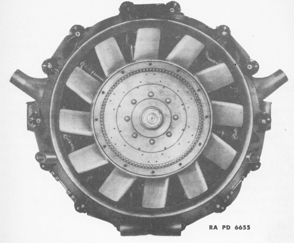
The flywheel end of the Continental W-670-9A was considered the front, and left and right were determined by looking at the engine from the rear. (Picture from TM 9-1726 Ordnance Maintenance--Continental Engine, Model W670-9A.)
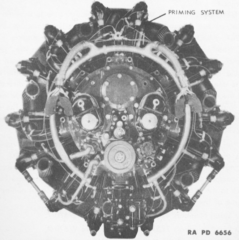
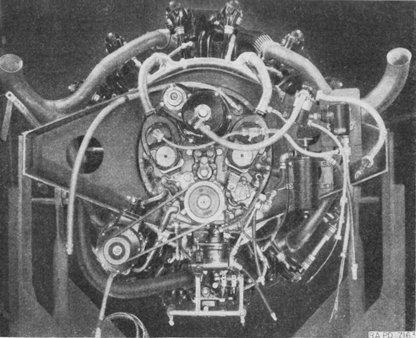
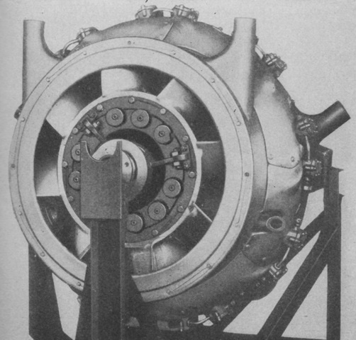
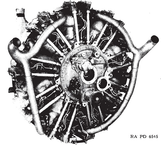
The rear of the engine is shown here, without the exhaust manifolds and piping mounted. (Picture from TM 9-1726 Ordnance Maintenance--Continental Engine, Model W670-9A.)
Seen again from the rear with accessories present, the engine's bore and stroke were 5.125" and 4.625" (13.02cm and 11.75cm), respectively, for a displacement of 667.86in³ (10.944L). (Picture from TM 9-726 Light Tank M3.)
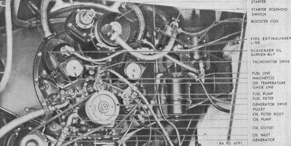
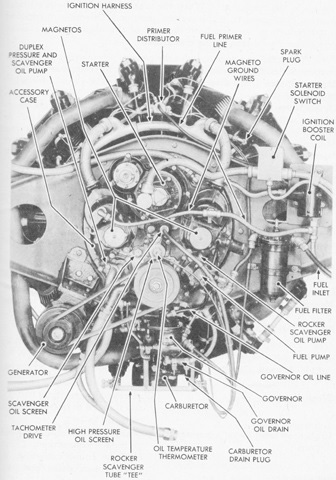
The Continental's accessories are labeled in this image. The engine was 42.375" (107.63cm) in diameter and weighed 1,107lb (502.1kg) with accessories. (Picture from TM 9-726 Light Tank M3.)
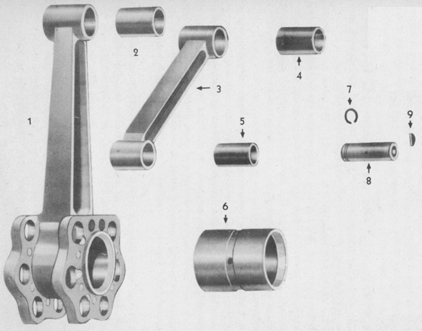
The master rod and one articulated rod are shown here with their bushings. The master rod received the knuckle pins of the six articulated rods, and the entire assembly was installed onto the crankshaft journal. 1. Master rod. 2. Master rod pin bushing. 3. Articulated rod. 4. Articulating rod piston pin bushing. 5. Knuckle pin bushing. 6. Crankshaft journal bearing. 7. Knuckle pin circlip. 8. Knuckle pin. 9. Woodruff key. (Picture from TM 9-1726 Ordnance Maintenance--Continental Engine, Model W670-9A.)
This is a top-down view into the engine compartment with the engine removed. (Picture from TM 9-726 Light Tank M3.)
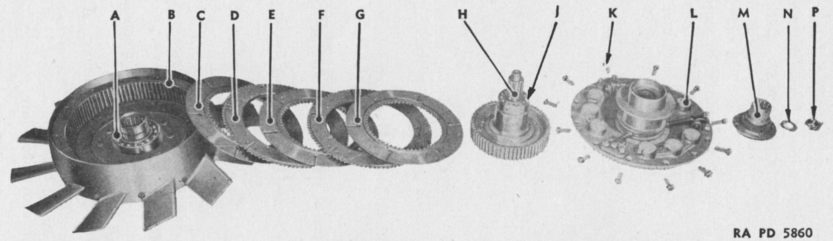
An exploded view of the vehicle's clutch is provided here. A. Inner hub bearing. B. Flywheel. C. Unlined plate. D. Lined plate. E. Unlined plate. F. Lined plate. G. Unlined plate. H. Spindle. J. Spindle bearing. K. Spring housing cap screw. L. Spring housing. M. Driven hub. N. Washer. P. Nut. (Picture from TM 9-726 Light Tank M3.)
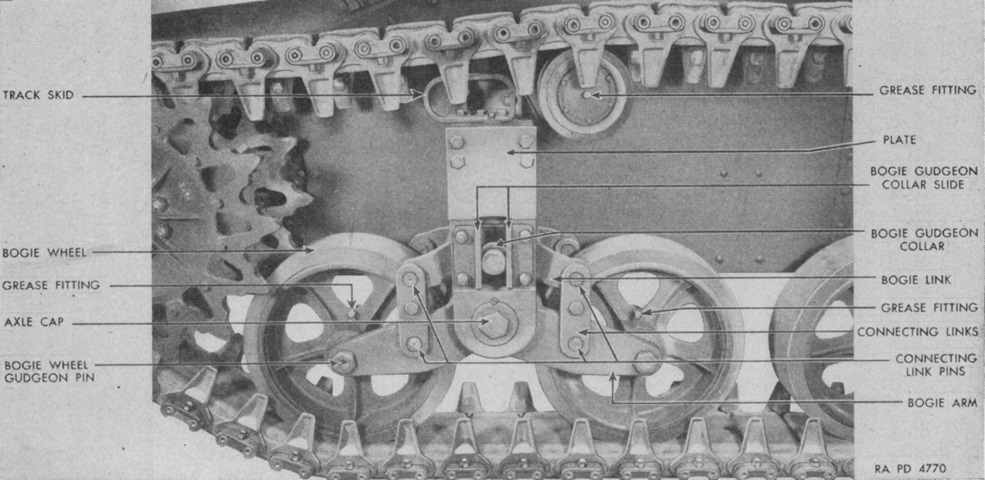
Details of the front suspension bogie are provided in this image. (Picture from TM 9-726 Light Tank M3.)
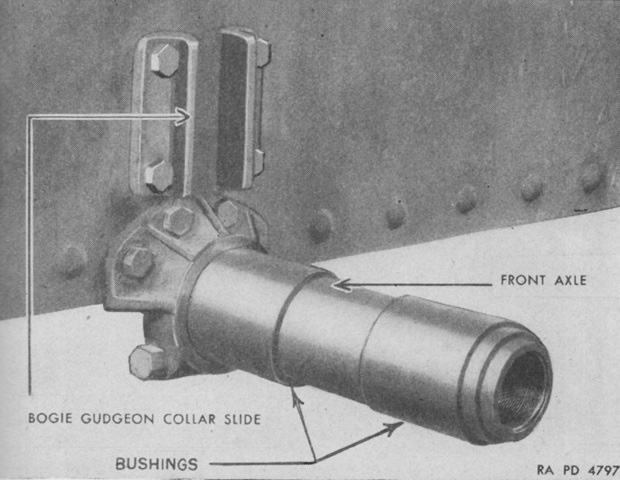
The suspension bogies were trunnioned on axles bolted to the hull sides and floor. The bushings that acted as the suspension's bearing surfaces were made of hardened steel. (Picture from TM 9-726 Light Tank M3.)
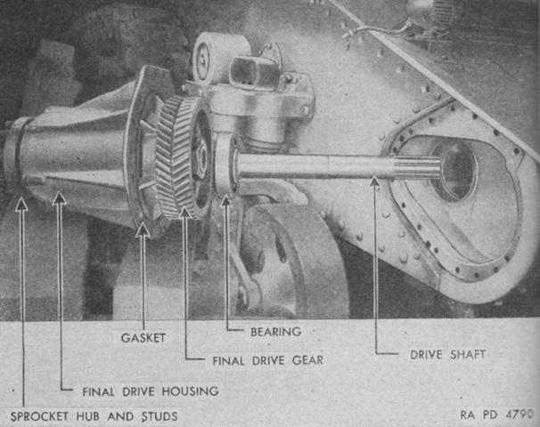
The right-side final drive has been disassembled in this picture. (Picture from TM 9-726 Light Tank M3.)
The transmission is shown here in the process of being removed. Using arm personnel were permitted to remove and reinstall an engine or transmission, but their replacement with a different engine or transmission required authorization from ordnance personnel. (Picture from TM 9-726 Light Tank M3.)
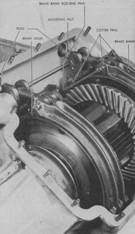
The differential case has been opened, revealing the gearing and steering brakes. (Picture from TM 9-726 Light Tank M3.)
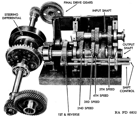
The complete transmission gearing is shown here. First and reverse were sliding gears, while second through fifth gears were synchromesh. (Picture from TM 9-1728 Ordnance Maintenance--Power Train for Light Tanks M3 and M3A1.)
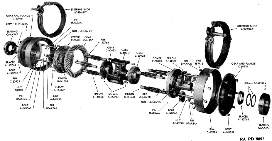
An exploded view of the steering differential is provided in this image. (Picture from TM 9-1728 Ordnance Maintenance--Power Train for Light Tanks M3 and M3A1.)
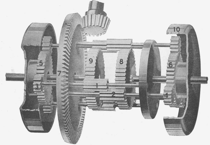
The controlled differential is further illustrated in this picture. When moving straight ahead, the entire assembly driven by the bevel pinion rotated as one. The differential pinions did not rotate in their bearings, and the main drive shaft gears turned at equal speeds. The steering drum gears and brake drums turned as one with the entire differential. When making a right-hand turn, the right steering lever was pulled back, contracting the brake band and stopping the right brake drum (10). The right-hand external (4) and internal (2) pinions with their shafts in their bearings would then rotate with the crown wheel (7). This would cause the left-hand pinions (1, 3) to turn in opposite directions. The right-hand external pinions (4) would then be rotating around the stationary brake drum gear (6) and turning the same direction, which would make the right main drive shaft gear (8) and shaft turn at a slower speed. The left differential pinions (1) would then be rotating in the opposite direction to the crown wheel (7) with the entire assembly turning in the same direction as before so that the left main drive shaft gear (9) and shaft rotate faster than the crown wheel since the right main shaft gear (8) and shaft have been slowed. Hence, when the right hand brake drum was stopped, the right main drive shaft spun at a slower rate while the speed of the left was increased. (Picture from Handbook on M2A4, M3 and M3A1 Light Tanks.)
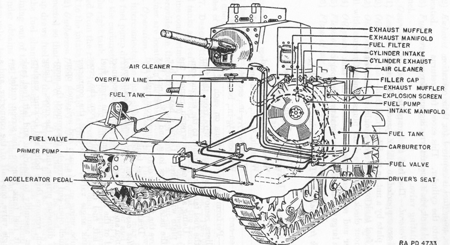
A vertical 28gal (110L) fuel tank was installed on rubber spacers in a wooden-lined pocket at each side of the forward engine compartment. In the Continental-engine tanks, as illustrated above, the tanks were connected so that either or both could be used. Fuel was drawn from the tank to the carburetor via a fuel pump, and excess was returned to the top of the right fuel tank. The priming pump on the instrument panel was also fed from the right tank. (Picture from TM 9-726 Light Tank M3.)
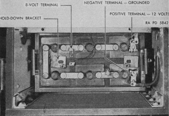
The compartment for the 12-volt storage battery was in the right rear sponson and was only accessible from the outside. Radio take-off terminals were supplied for 12, 8, and 2 volt requirements. (Picture from TM 9-726 Light Tank M3.)
As opposed to earlier machines, this tank features protectoscopes in the turret pistol ports and the drivers' doors. Protected peepholes for the drivers remained inboard and below the protectoscopes. No peepholes are present in the commander's cupola. (Picture from TM 9-726 Light Tank M3.)
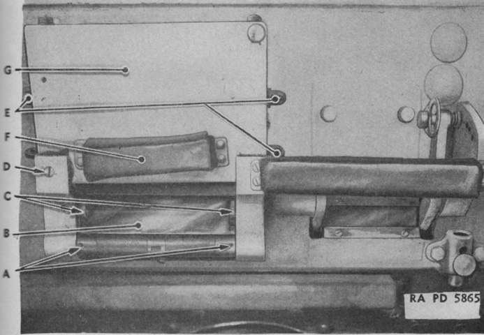
A protectoscope in one of the drivers' doors is detailed in this picture. A. Headless set screw. B. Window No. 1. C. Ledge. D. Brass countersunk screw. E. Fastening pins. F. Headrest. G. Door. (Picture from TM 9-726 Light Tank M3.)
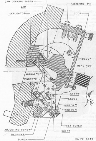
The protectoscopes in the drivers' doors are cross-sectioned here. A recess in the deflector behind mirror #2 prevented bullets or fragments from ricocheting into the lower mirrors and windows or into the user's eyes. (Picture from TM 9-726 Light Tank M3.)
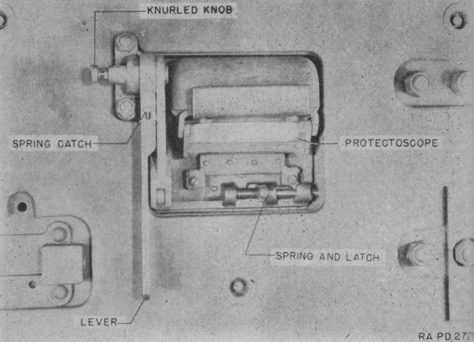
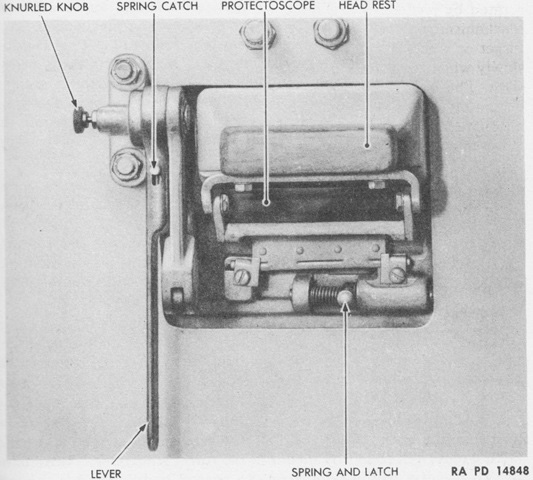
A turret pistol port protectoscope is seen here from the tank's interior. To open the pistol port door, the lever locking the spring catch was moved down, then raised until the knurled knob dropped into the notch in the lever. The cover bolt was unlatched, then the lever was pulled down until the knurled knob dropped into place again, locking the door open. (Picture from TM 9-726 Light Tank M3.)
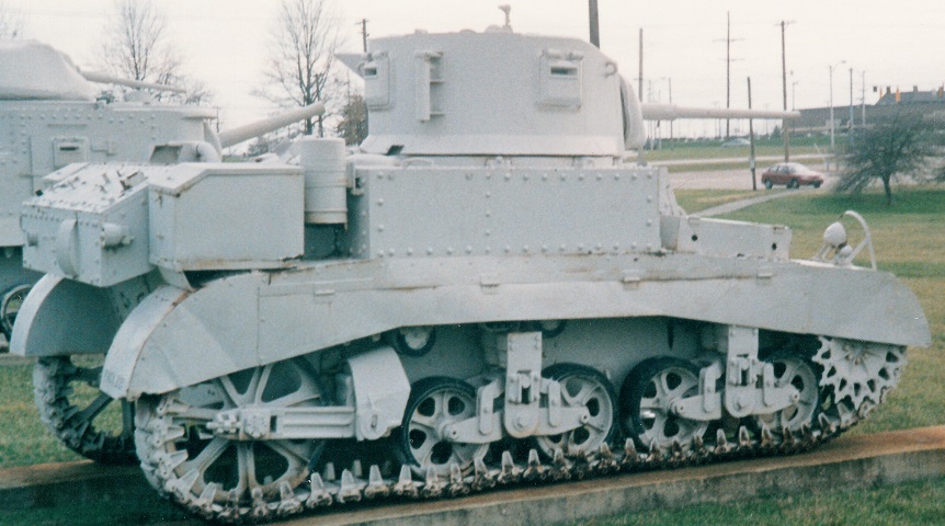
This gasoline-engined tank has the round turret and cupola featuring the split hatch, which is open. The sponson machine gun openings have been plated over, but the bow and coaxial machine guns are visible. The two volute springs per suspension bogie can also be seen from this angle.
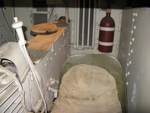
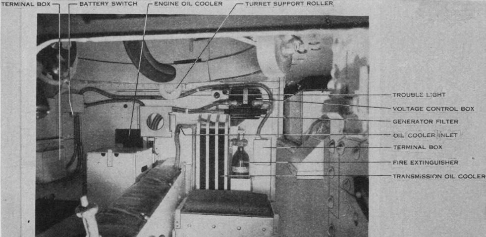
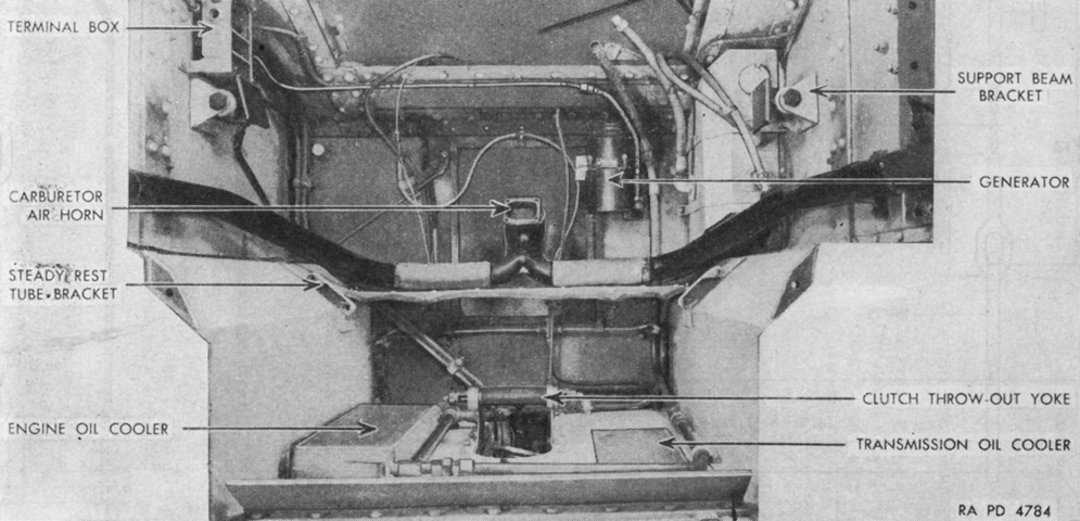
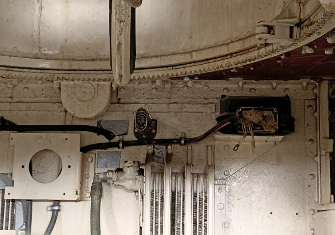
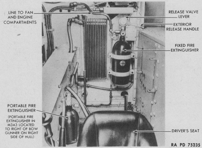
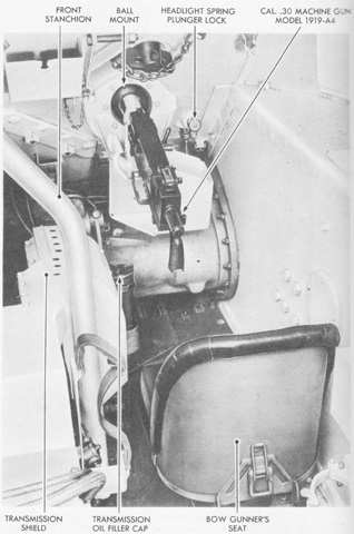
This image is looking through the open driver's hatch towards the rear of the fighting compartment. The propeller shaft and its housing bisects the interior, and a padded gunner's seat was normally provided all along the top of this housing. The location of the fixed fire extinguisher is seen directly behind the driver. The gear shift hand lever is positioned to the driver's right, on the left side of the transmission. The button on top needed to be pressed in order to shift into first or reverse gears. The transmission oil cooler is beside the fire extinguisher bottle behind the driver, and the engine oil cooler occupies the similar spot on the opposite side of the propeller shaft housing.
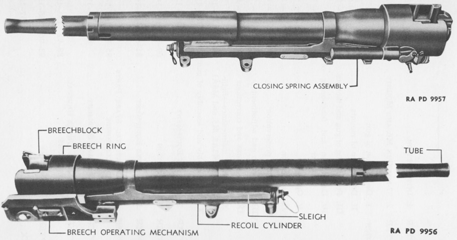
The 37mm gun M6 is shown here from each side. It weighed 185lb (83.9kg) total, with the tube itself weighing 138lb (62.6kg). The vertical sliding breechblock weighed 7.5lb (3.4kg). (Picture from TM 9-250 37-mm Gun M6, Mounted in Combat Vehicles.)
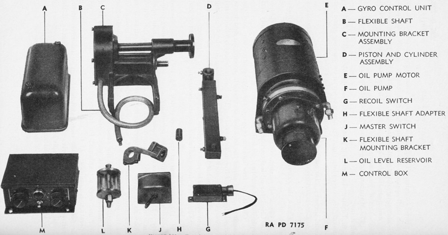
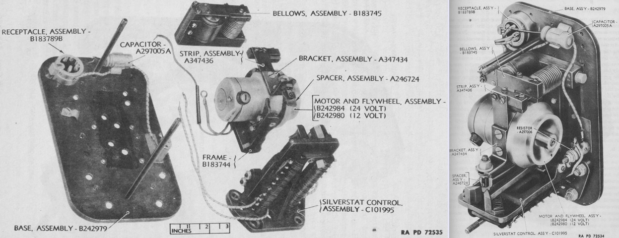
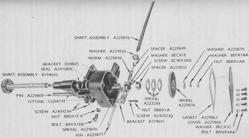
The different assemblies that made up the gyrostabilizer are labeled. (Picture from TM 9-726 Light Tank M3.)
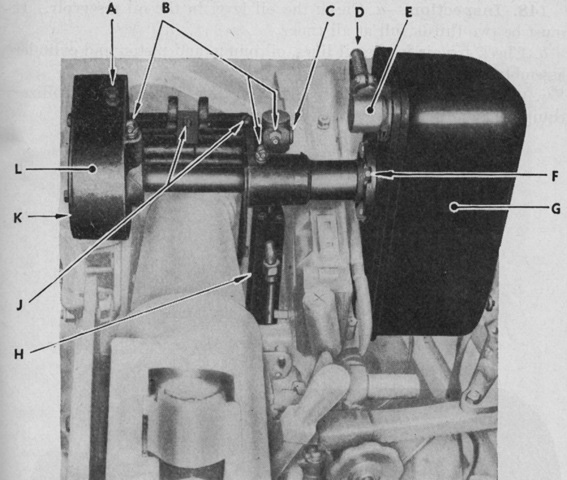
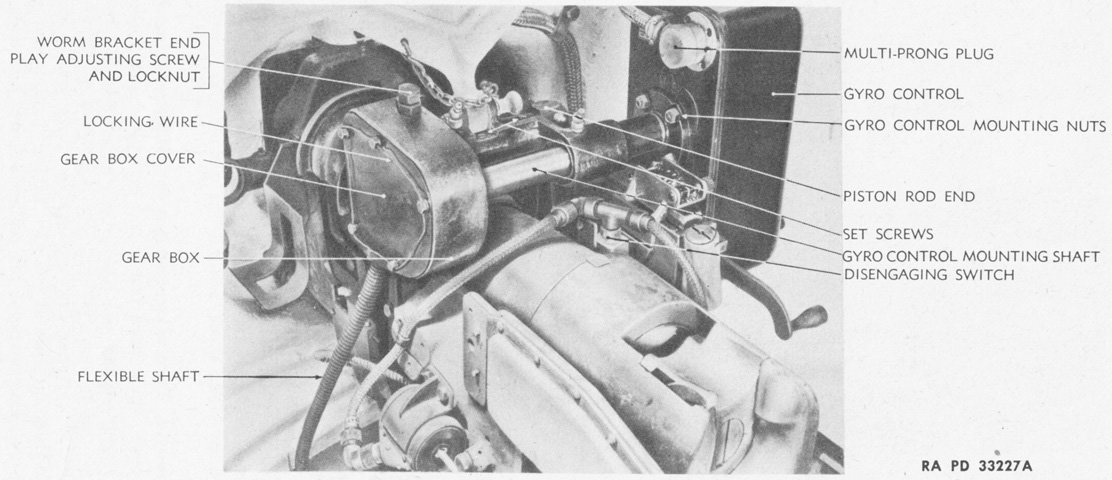
The gyrostabilizer components are installed; the breech of the 37mm gun can be seen in the lower left quadrant of the image. A. Worm bearing adjustment. B. Grease fittings. C. Piston rod pivot pin. D. Shielded conduit. E. Multi-prong connector. F. Gyro control mounting bolts. G. Gyro control unit. H. Piston cylinder assembly. J. Set screws. K. Gear cover plate. L. Mounting bracket assembly. (Picture from TM 9-726 Light Tank M3.)

The lower end of the gyrostabilizer cylinder and flexible shaft bracket are shown here. A. Firing pin cable. B. To upper cylinder connection. C. Set screw and lock nut. D. Elbow. E. Cylinder. F. Clamp screw. G. Flexible shaft. H. Flexible shaft bracket. J. To lower pump connection "B." K. Oil return line. L. Collar. M. To upper pump connection. (Picture from TM 9-726 Light Tank M3.)
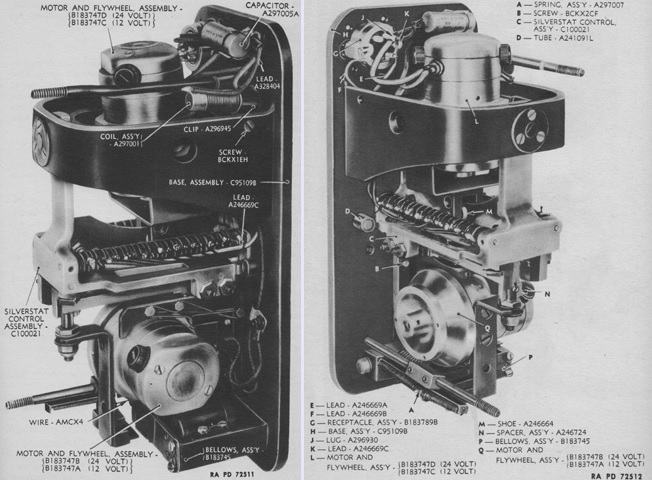
Originally, the gyro control units contained two gyroscopes; two views of an assembled double-gyro control unit are shown here with the cover removed. These had no identification or instruction plate on the cover, but a name plate was attached to the base. The motors were 12 volts direct current in light tanks and 24 volts in medium tanks, rotating at 12,500-16,000rpm. The upper gyro was pendulous, hanging vertically on two frictionless bearings. The lower gyro was mounted horizontally on frictionless bearings. The upper gyro was used to keep the cradle with the silverstat control hanging vertically, as the silverstat's vertical position was used as a reference point for the stabilizer. When the gun's angle changed, the upper gyro would precess back to vertical, and the lower gyro would operate the silverstat contacts via the micarta spacer attached to the lower gyro. The making and breaking of these contacts varied the flow of oil through the electrically-controlled oil valves in the oil pump, which then flowed to the appropriate side of the cylinder and piston, finally moving the gun in the desired direction. (Picture from TM 9-1334 Ordnance Maintenance--Stabilizers.)
Stabilizers with two gyros were found to be adversely affected by the movement of their own tanks, and were replaced by stabilizers with mono-gyro controls. The silverstat control was fixed, and the upper gyro was the one that was eliminated. The micarta spacer bracket on the gyro made the motor heavier on the side of the pivot pins, and consequently the bracket side of the gyro was the side that tipped toward vertical and closed the silverstat connections. As this was the opposite side versus the double-gyro control, the mono-gyro control was assembled upside-down relative to the double-gyro control except for the multi-prong plug and capacitor. The mono-gyro offered less resistance when the tank was standing still; therefore, the stiffness could not be checked by simply pushing down on the breech, as with double-gyro controls. Mono-gyros also required the elevation handwheel to be rotated a bit faster than with double-gyro controls, where a slight movement of the handwheel would result in elevation change. Instead of using the exact position of the gyro control relative to the gun as the determining factor for changing the gun elevation, as double-gyro controls did, mono-gyro controls used the rate of turning of the elevation handwheel. Consequently, mono-gyro controls could slope up to 60� from vertical when influenced by the balance and friction of the gun mount, temperature, and oil pump characteristics, and might not always return to their exact starting point when disturbed. (Picture from TM 9-1334 Ordnance Maintenance--Stabilizers.)
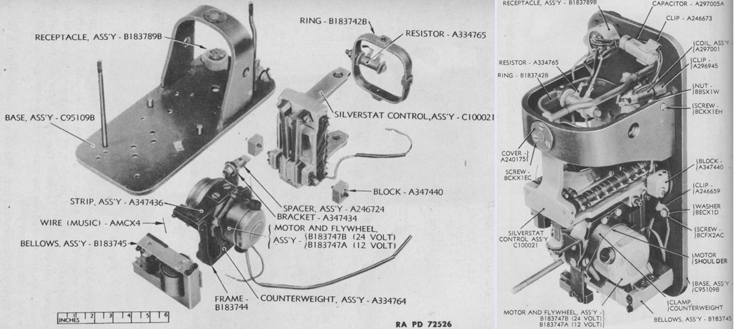
Once it was found that mono-gyro controls were an improvement, double-gyro controls were field modified into single-gyro controls via Field Service Modified Work Order C-56W1 from 24 May 1943, and such a gyro control is illustrated here. The identification or instruction tag on the cover noted that the gyro control was "MODIFIED." The modified gyro control worked like a mono-gyro control, except that the assemblies inside were in the same position as found in the double-gyro, i.e., not upside-down. The complete assembly could not be turned upside-down to use the micarta spacer bracket as a reference, so a counterweight was attached to the motor. This counterweight made the motor heavier on the side of the pivot pins, and this side therefore swung back to vertical and brought the micarta spacer in contact with the silverstat leaves. (Picture from TM 9-1334 Ordnance Maintenance--Stabilizers.)
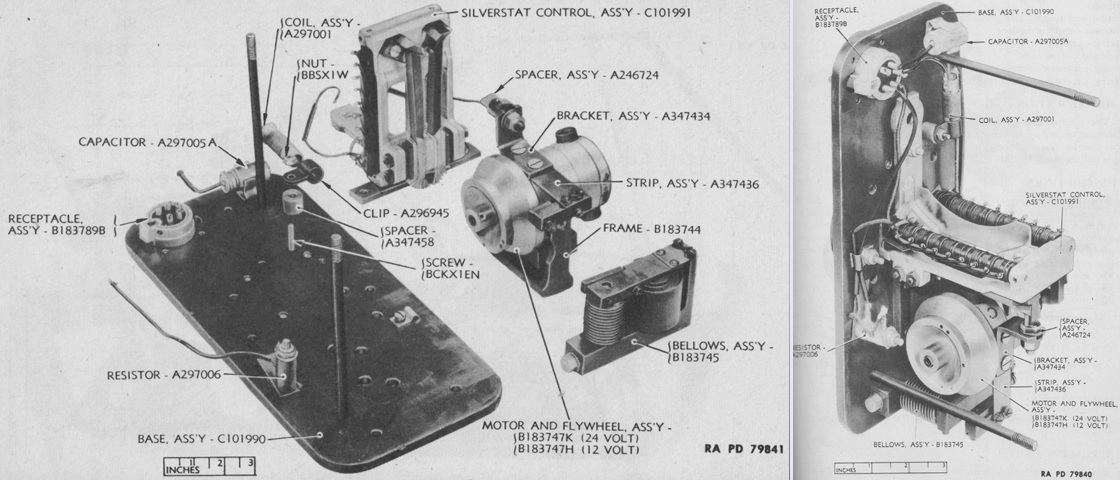
Mono-gyro controls were also factory produced using double-gyro bases and covers in order to use up stocks of these parts. An identification tag was attached to the cover that was similar to that of the modified gyros, except that they were not marked as "MODIFIED." Like the modified gyro, the assemblies were not upside-down compared to the double-gyro, and a counterweight was again attached to the motor. (Picture from TM 9-1334 Ordnance Maintenance--Stabilizers.)
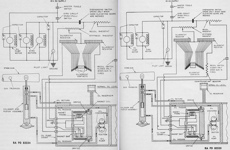
The wiring diagrams for double- and mono-gyro control stabilizers are shown on the left and right, respectively. Medium tanks were similar except for the mounting of the cylinder and piston as well as instead using a 24-volt system instead of 12. (Picture from TM 9-1334 Ordnance Maintenance--Stabilizers.)
An exploded view of the gyro control gearbox used in light tanks is provided in this image. The gearbox regulated the angular relationship between the gyro control and the gun. The gearbox was attached to the gun mount, and the gyro control was fastened to the gearbox's worm wheel. A flexible shaft entering the gearbox changed the position of the gyro control relative to the gearbox by turning a worm gear which was meshed with the worm wheel. Unlike medium tanks, which featured a clutch on the gyro control, light tanks mounted the clutch on the gearbox between the worm wheel and the gyro control mounting shaft. (Picture from TM 9-1334 Ordnance Maintenance--Stabilizers.)
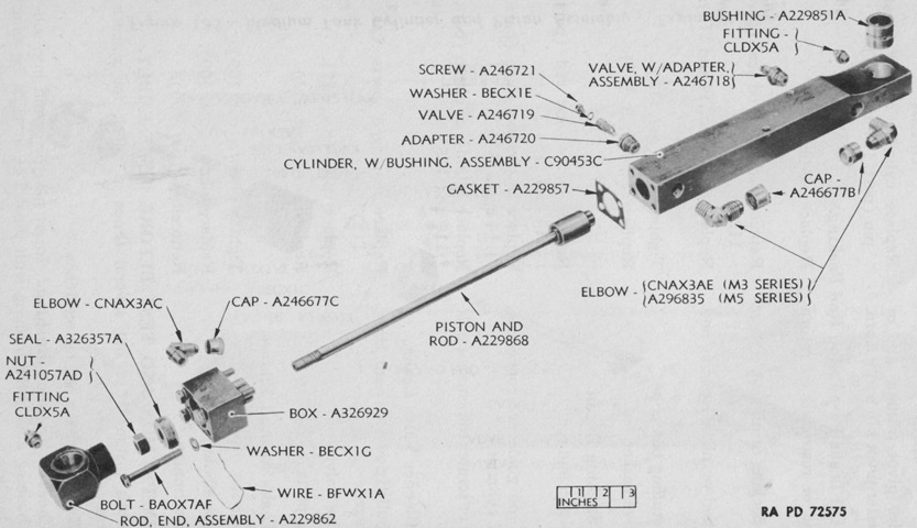
An exploded view of the stabilizer's cylinder and piston assembly is diagrammed here. The piston rod was attached to the gun, while the cylinder was fastened to the turret. Two ⅜" (.953cm) oil lines from the oil pump allowed pressure to act on both sides of the piston. A ¼" (.64cm) line returned oil to the oil pump that leaked by the piston rod into the stuffing box. Very early in production, two bleeder valves were introduced to allow the removal of air without cracking the oil lines. The cylinder could be sealed with an oil seal, as illustrated here, or with chevron-type packing, which required an additional guide for the rod. (Picture from TM 9-1334 Ordnance Maintenance--Stabilizers.)
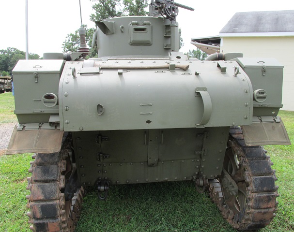
The air cleaner pipes on the diesel-powered tanks were longer than those with gasoline engines. The angled bracket with the single perforation on the right side of the rear deck was the mount for the radio's antenna base.
The longer air cleaner pipes are better seen from this angle.
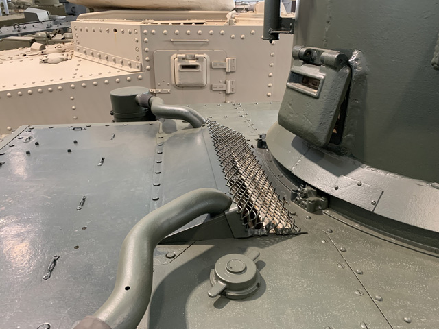
The fuel fillers remained in a similar location compared to the gasoline-fueled tanks. The two rear turret bearing and roller brackets are visible in front of the air intake screen.
The Guiberson T-1020-4 engine is shown here. It displaced 1,021in³ (16.73L). (Picture from TM 9-726 Light Tank M3.)
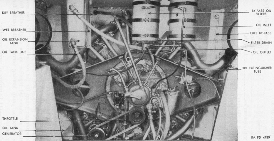
The Guiberson is shown here installed in the engine compartment. Its overall diameter was 45.4375" (115.411cm), and it weighed 1,107lb (502.1kg) with accessories. (Picture from TM 9-726 Light Tank M3.)
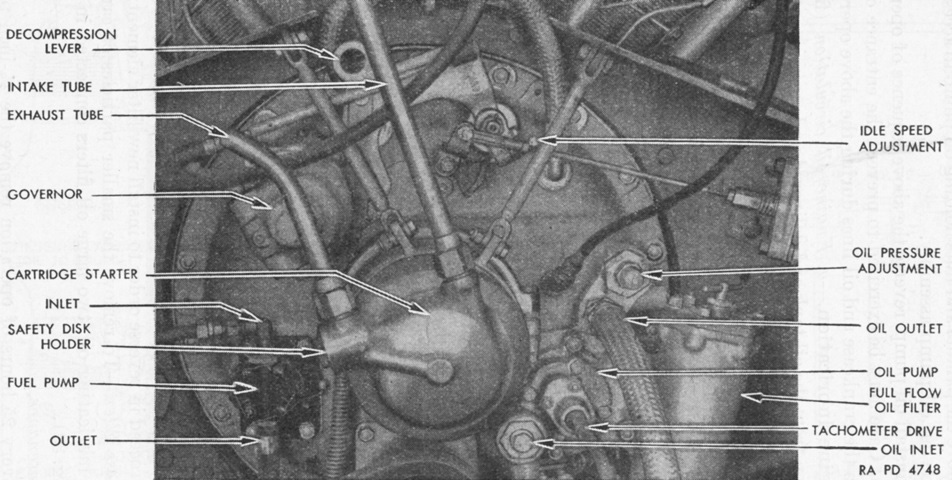
A closer look at the accessory case is given in this image. (Picture from TM 9-726 Light Tank M3.)
The rear of the Guiberson illustrated here, including the exhaust manifolds. (Picture from TM 9-1727 Guiberson Engine, Model T-1020.)
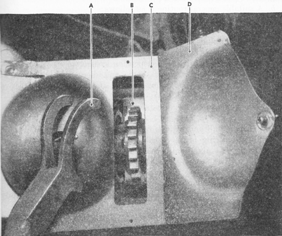
Both the gasoline and diesel engines were required to be turned over by hand before starting. Late Guiberson-engined tanks a hand cranking ratchet on the propeller shaft. A. Propeller shaft turning wrench. B. Propeller shaft ratchet. C. Propeller shaft housing. D. Hand cranking aperture cover. (Picture from TM 9-726 Light Tank M3.)
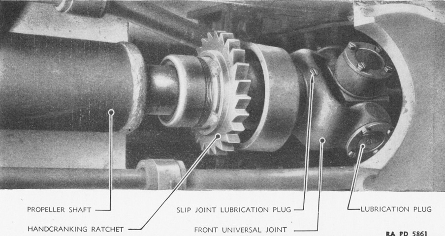
The propeller shaft housing has been removed in this picture. (Picture from TM 9-726 Light Tank M3.)
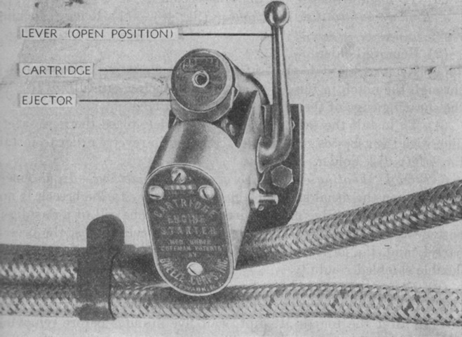
The Guiberson was equipped with a starter shared with their medium tank diesel radials that spun the engine by gas pressure generated from the firing of a cartridge. The starter breech assembly, located in the driver's compartment, is shown here in the open position. The cartridge was given three attempts to fire, and if all failed it was left in the breech for at least five minutes before removal. The breech and starter assemblies were to be replaced after 100 hours of operation. (Picture from TM 9-726 Light Tank M3.)
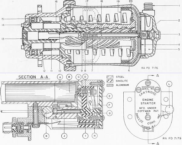
Cross-sections of the cartridge starter unit and the breech assembly are sketched at the top and bottom, respectively. When a cartridge was fired, gas pressure was transmitted to the combustion chamber from the breech through the intake tube, forcing the piston to the position depicted by the dotted lines. The piston's initial travel would cause the external and internal splined shaft to move and engage the starter jaw assembly with the jaw of the engine's crankshaft. The piston movement would also impart ~5/12 of a rotation to the external and internal splined shaft, resulting in ~⅚ of a rotation being transmitted to the starter jaw. As the piston reached the dotted position, it would compress the exhaust valve opening spring, which would decrease pressure in the cylinder and let the piston return spring act on the piston to send it back to its starting position. The legend for the starter unit is: 1. Intake tube connection. 2. Groove. 3. Exhaust valve. 4. Disk. 5. Combustion chamber. 6. Piston return spring. 7. Exhaust valve opening spring. 8. Exhaust valve closing spring. 9. Starter jaw bolt. 10. Finger spring. 11. Shaft assembly. 12. Shoulder of jaw assembly. 13. Hollow screw. 14. Starter jaw assembly. 15. Thrust ball bearing. 16. Hub assembly. 17. External and internal helical splined shaft. 18. Exhaust valve bolt. 19. Piston. 20. Retaining ring.
The legend for the breech assembly is: A. Barrel. B. Contact pin. C. Breechblock. D. Contact pin spring. E. Contact pin lever. F. Contact pin lever shaft. G. Plunger spring. H. Breech housing. I. Center block plunger. J. Breech locking bolt. K. Breech opening lever. L. Breech opening lever, closed position. (Picture from TM 9-1731 Ordnance Maintenance--Breeze Cartridge Starter for Radial Diesel Engines.)
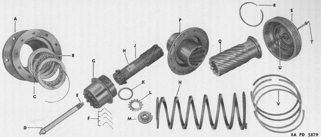
Internal parts of the starter unit are laid out in this image. A. Housing assembly. B. Bearing. C. Bearing lock ring. D. Starter jaw bolt. E. Exhaust valve closing spring. F. L-shape springs. G. Starter jaw assembly. H. Finger spring rivet. J. Steel shaft assembly. K. Hollow steel gasket. L. Hollow screw lock plate. M. Hollow screw. N. Piston return spring. P. Hub assembly. Q. Bronze external and internal helical spline shaft. R. Lock ring. S. Piston. T. Exhaust valve control bolt. U. Exhaust valve opening spring. V. Piston rings. (Picture from TM 9-1731 Ordnance Maintenance--Breeze Cartridge Starter for Radial Diesel Engines.)
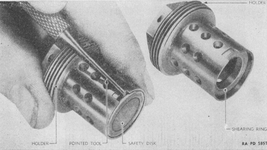
The maximum pressure for the starter system was guaranteed by a safety disk composed of light sheet copper on one side and asbestos on the side facing the flame in the combustion chamber. If the pressure exceeded 3,000psi (210kg/cm²) the disk would rupture and the pressure would be vented to the atmosphere. The safety disk is shown here in its stainless steel holder assembly. (Picture from TM 9-1731 Ordnance Maintenance--Breeze Cartridge Starter for Radial Diesel Engines.)
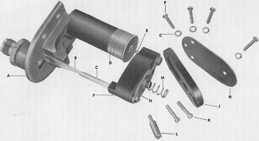
Parts for the breech electrical circuit are shown in this picture. A cartridge is also present. A. Flange assembly. B. Contact blade. C. Contact stem. D. Cartridge. E. Contact pin. F. Breech end cover plate attaching screws. G. Lock washers. H. Breech end cover plate. J. Breech end plate. K. Center block attaching screws. L. Center block attaching stud. M. Center block plunger spring. N. Electrical connector. P. Center block assembly. (Picture from TM 9-1731 Ordnance Maintenance--Breeze Cartridge Starter for Radial Diesel Engines.)
The starter was located on the engine compartment bulkhead to the rear of the driver above the engine oil cooler.
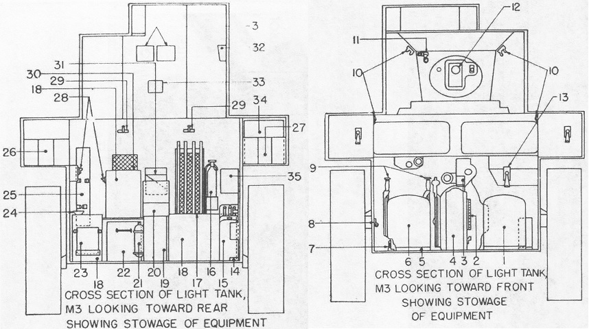
Internal stowage is detailed in these sketches. 1. Bow gunner's seat. 2. Bracket for 2-45 cal. [sic] drums. 3. Protectoscope box. 4. Power tunnel. 5. Canvas bucket. 6. Driver's seat. 7. Door handle bracket. 8. Diesel engine crank bracket. 9. Steering levers. 10. Flashlight clip. 11. Compass. 12. 37 mm gun. 13. Bow gun. 14. Bracket for 2 spare barrels. 15. Water can. 16. Fire extinguisher, fixed. 17. Oil cooler. 18. 37mm [sic] ammunition box. 19. Power tunnel. 20. Tool box. 21. Portable fire extinguisher. 22. Ration box, excess rations in right rear equipment box. 23. First aid box bracket. 24. Oil can bracket. 25. 45 cal. [sic] Thompson sub machine gun bracket. 26. 3-30cal. [sic] ammunition boxes. 27. Cal. .30 ammunition boxes. 28. Canteen racks-2. 29. Handle for jettison tanks. 30. Signal flags behind 37 mm ammunition box. 31. Box for 50 rounds 45 cal. [sic] drums. 32. Binocular box. 33. Pistol port. 34. Radio. 35. Hand grenade box. (Picture from TM 9-726 Light Tank M3.)
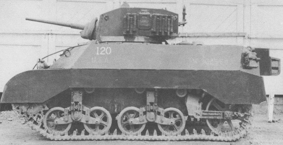
Notice the riveted hull and and round turret lacking a cupola on this Stuart III. The turret front plate is welded on, however. The openings for the sponson machine guns have been plated over with round steel plugs. The tracks on this example are either the T16E1 or T16E2 rubber block tracks. The opening for the gunner's telescope is on the left of the 37mm gun M6, and the coaxial machine gun would emerge from the right of the gun.
In contrast, this later-production machine has a welded hull. (Picture from TM 9-727 Light Tanks M3A1 and M3A3.)
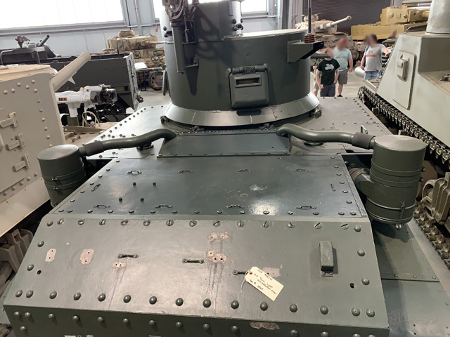
This side view offers a good view of the tank's trailing idler suspension, which is shrouded by sandshields. The air cleaners are visible between the sponson and stowage boxes to the rear. On this tank, also gasoline-powered, the pipes curve into the rear deck immediately from the air cleaner. Between the pistol port doors on the turret is the M20 anti-aircraft mount for the .30cal MG.
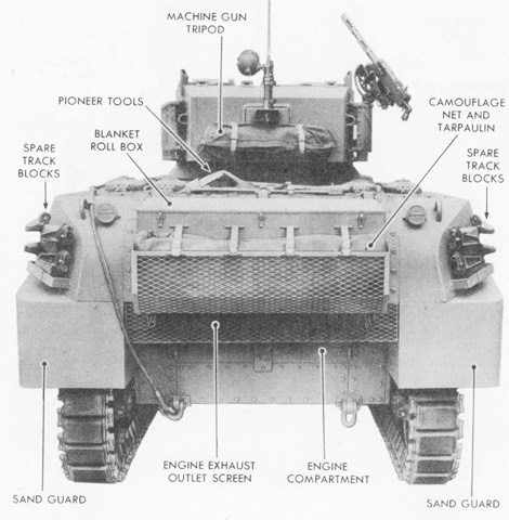
Stowage and the upper surfaces are visible in this picture. (Picture from TM 9-727 Light Tanks M3A1 and M3A3.)
The short air intake tubes indicate this is a gasoline-fueled tank. (Picture from TM 9-727 Light Tanks M3A1 and M3A3.)
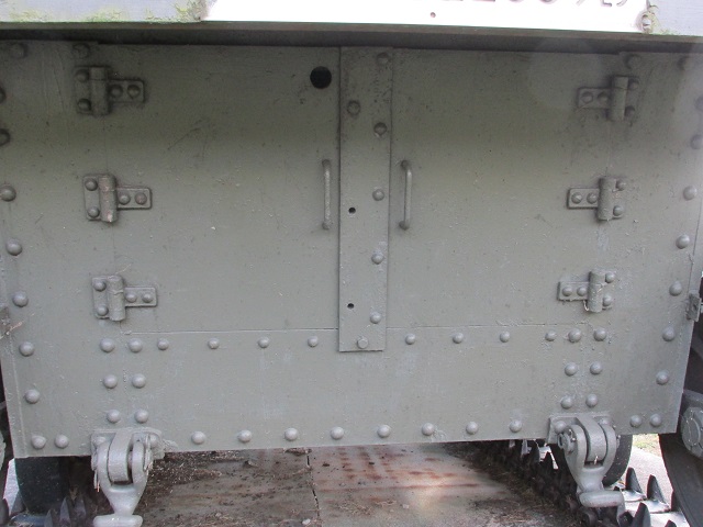
Stowage boxes sit on the rear fenders of the tank, and a shovel would normally be mounted in the bracket on the hull rear. The small hole in the center of hull rear below where the shovel would be mounted was for the engine hand crank. A radio antenna is mounted in the left hand hull mount, but the antenna mount on the opposite side of the hull is empty. Two engine access doors can be seen on the lower rear hull, and a towing clevis is mounted on each side of the tank below these doors.
Looking under the rear hull armor, we can see the engine exhaust muffler on the right side of the vehicle. Further details of the engine access doors and hinges can also be seen.
The internal arrangement of the M3A1 can be contrasted with the earlier tank above. Note the turret basket and the power traverse mechanism under the turret seats. (Picture from Tank Data, vol. 2.)
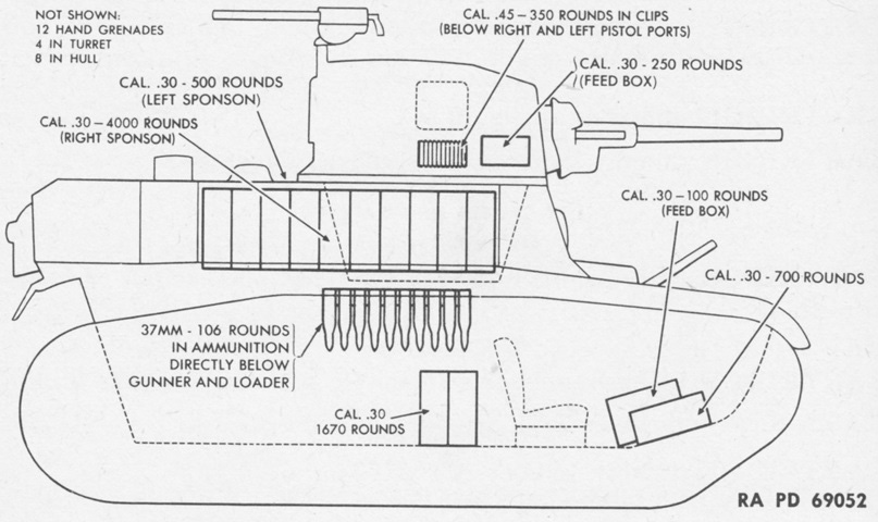
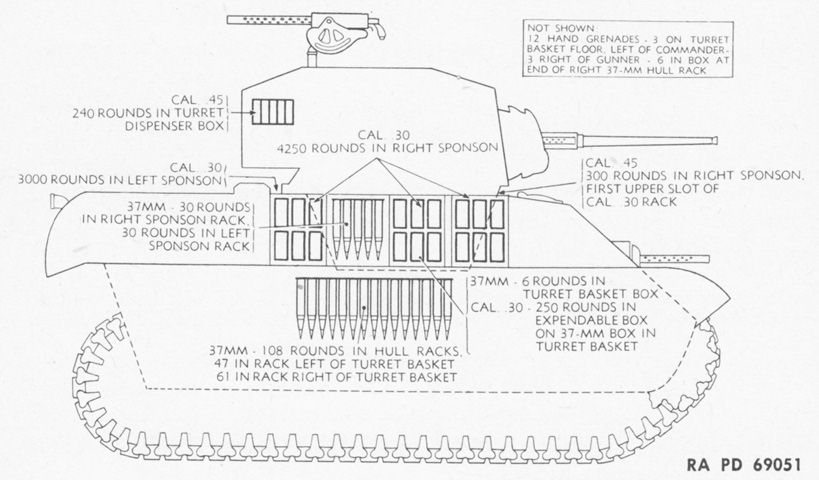
Ammunition stowage is diagrammed in this sketch. (Picture from TM 9-727 Light Tanks M3A1 and M3A3.)
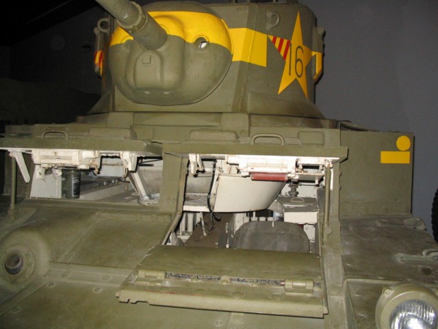
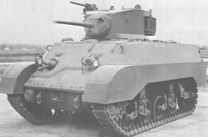
This is a later-production M3A1, as evidenced by the lack of holes for the sponson machine guns, as well as a dearth of rivets on the hull. The driver's and assistant driver's doors are open, and it is evident that the assistant driver would have a very tough time exiting the vehicle under duress, since the bow machine gun takes the place of a second door in the hull. The driver could open a door in the front hull plate as well as the door with his vision devices, but the assistant driver must exit through the turret. The driver's seatback is apparent, as is the turret basket. The propeller shaft can be seen running between the drivers. The turret seats, as well as the traversing mechanics, seem to be missing from this vehicle.
The turret interior layout is diagrammed here. (Picture from TM 9-727 Light Tanks M3A1 and M3A3.)
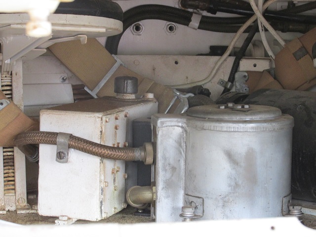
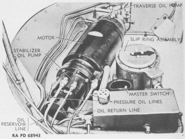
This vehicle does have the turret traversing gear installed. The commander's seat is visible at the upper left of the image. The box directly below his seat is the hydraulic oil pot, and the cylindrical structure connected to the large braided hose is the slip ring assembly. Atop the slip ring was an arrow that pointed toward the hull front no matter the turret's orientation.
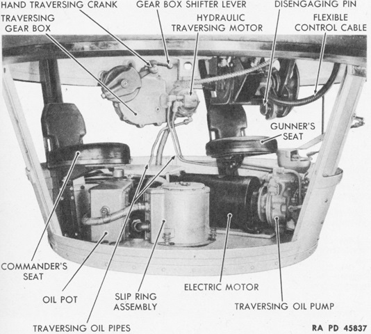
The crowded nature of the turret basket can be seen. The gearbox shifter lever activated either the manual or hydraulic traverse systems: when pushed towards the turret wall, manual traverse was selected, and when pushed away from the turret wall, the hydraulic system was selected. (Picture from TM 9-727 Light Tanks M3A1 and M3A3.)
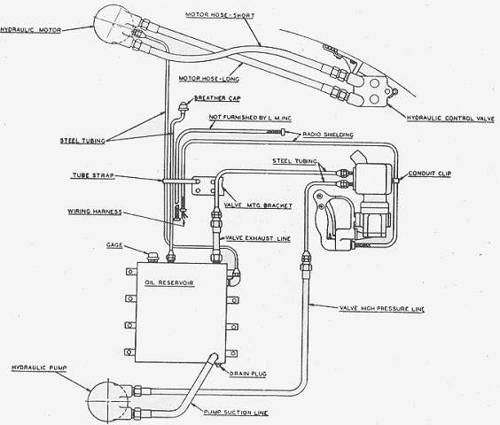
The Logansport turret traverse mechanism is diagrammed here. (Picture from Handbook on M2A4, M3 and M3A1 Light Tanks.)
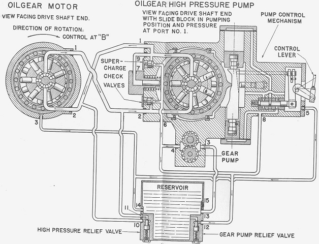
A competing turret traverse mechanism was manufactured by Oilgear. (Picture from Handbook on M2A4, M3 and M3A1 Light Tanks.)
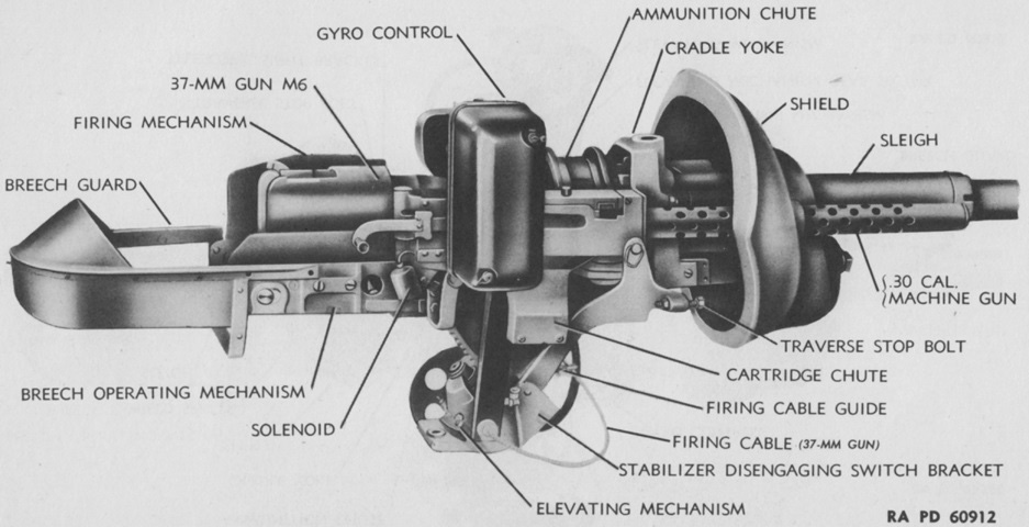
A stabilizer-equipped gun mount M23 is shown here from the right. (Picture from TM 9-250 37-mm Gun M6, Mounted in Combat Vehicles.)
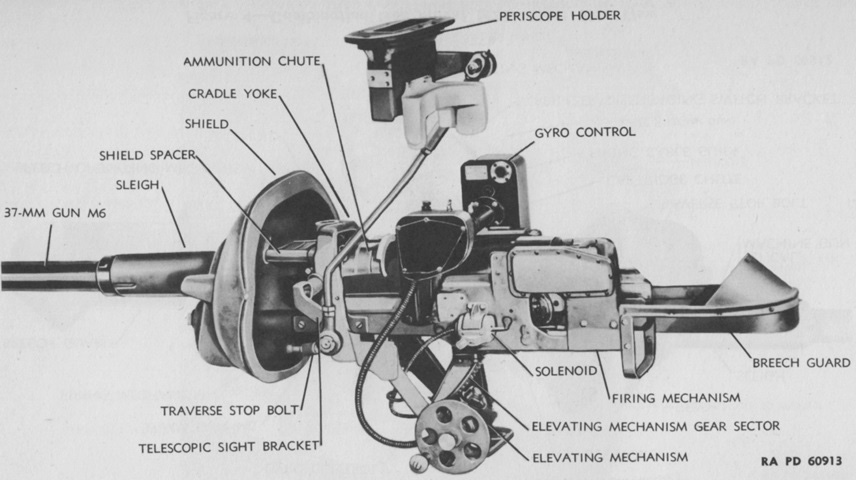
The opposite side of the gun mount is the subject of this picture. (Picture from TM 9-250 37-mm Gun M6, Mounted in Combat Vehicles.)
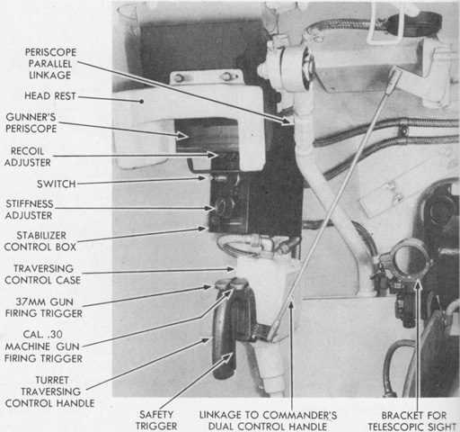
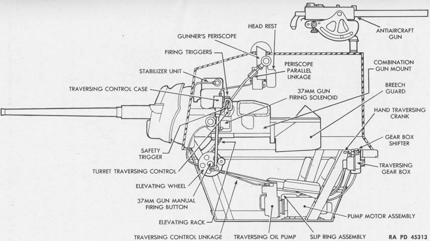
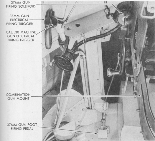
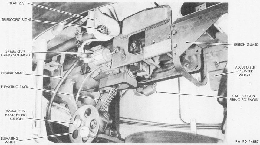
The gunner's controls are shown here. The turret traversing control handle was turned clockwise to traverse to the right, and vice-versa. The safety trigger on the handle needed to be squeezed to enable the firing of the guns, either electrically via the triggers on the handle or manually via a trigger on the elevation wheel. (Picture from TM 9-727 Light Tanks M3A1 and M3A3.)
The lower portion of the gunner's position is shown here. (Picture from TM 9-727 Light Tanks M3A1 and M3A3.)
Components of the stabilizer system mounted around the gun mount are labeled in this image. (Picture from TM 9-727 Light Tanks M3A1 and M3A3.)
The stabilizer assemblies on the gun mount are detailed here. (Picture from TM 9-727 Light Tanks M3A1 and M3A3.)
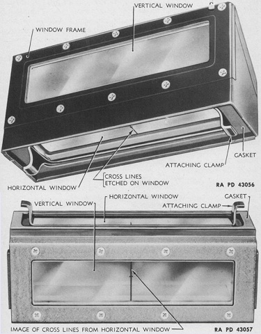
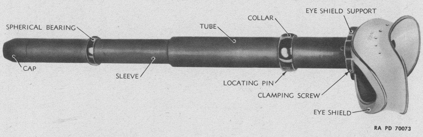
The head and elbow assemblies of the gunner's periscope M4 are at the top and bottom of the image, respectively. Cross lines were etched onto the horizontal window to be used as rough sighting aids in an emergency. (Picture from TM 9-727 Light Tanks M3A1 and M3A3.)
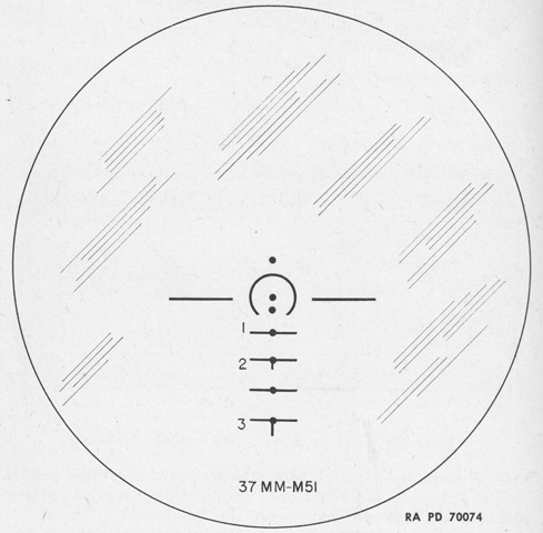
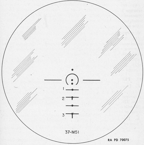
The telescope M40 was mounted on right side of the body of the periscope M4 between the upper and lower horizontal windows, with elevation and deflection adjustment mechanisms built in the periscope body. The M40 was a 1.44x erect-image telescope with a 9° field of view, and its reticle is sketched above. The range markings were calculated using the armor-piercing shot M51, as noted at the bottom of the reticle. The top dot was for zero range and deflection, and was at the reticle's geometric center. The arc below this dot had a 5-mil radius, and the dot in the center of the arc was for 600 yards (550m) range. The dot below this was for 1,000 yards (910m), and the horizontal lines below this dot represented 1,500, 2,000, 2,500, and 3,000 yards (1,400, 1,800, 2,300, and 2,700m). (Picture from TM 9-727 Light Tanks M3A1 and M3A3.)
This is the interior portion of a turret pistol port. (Picture from TM 9-727 Light Tanks M3A1 and M3A3.)
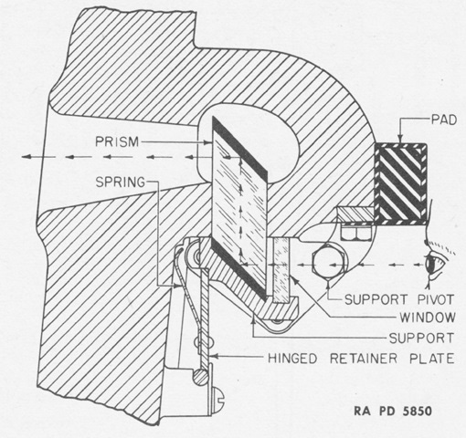
The principle of the protectoscope found in the turret pistol ports is drawn here. A pocket was designed to catch any incoming fire or fragments, protecting the eyes of the observer. Both the prism and window could be replaced without the use of tools. (Picture from TM 9-727 Light Tanks M3A1 and M3A3.)
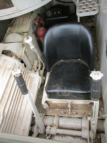
Compared to the view into the driver's compartment on the M3, the turret basket of the M3A1 dominates the space behind his seat and makes the cushioned propeller shaft housing unnecessary.
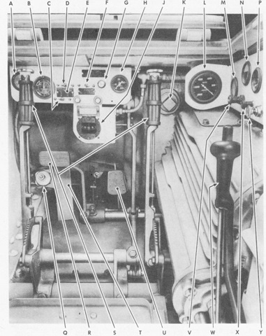
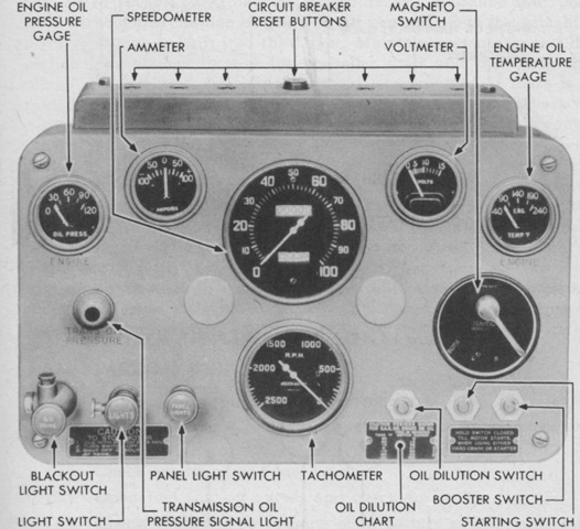
The front of the driver's compartment is shown here. A. Transmission oil pressure gage. B. Engine hour meter. C. Oil dilution switch. D. Starting switch. E. Oil dilution chart. F. Booster switch. G. Hand throttle. H. Engine oil pressure gage. J. Compass. K. Brake adjusting aperture plug. L. Tachometer. M. Engine oil temperature gage. N. Ammeter. P. Voltmeter. Q. Siren button. R. Clutch pedal. S. Steering levers. T. Footrest. U. Foot throttle. V. Light switch. W. Gearshift lever. X. Headlight dimmer switch. Y. Priming pump.
The oil dilution switch operated a valve below the engine compartment door sill that allowed gasoline from the fuel pump to mix with the engine oil inlet pipe connection at the bottom of the oil tank. This eased starting in colder temperatures. The booster switch activated a booster coil wired through the right magneto that provided a "hot" ignition spark when the engine was started. However this only applied if scintilla magnetos were installed; if Bosch magnetos were present the booster coil was not connected. (Picture from TM 9-727 Light Tanks M3A1 and M3A3.)
The rear of the Continental engine is shown in this image. (Picture from TM 9-727 Light Tanks M3A1 and M3A3.)
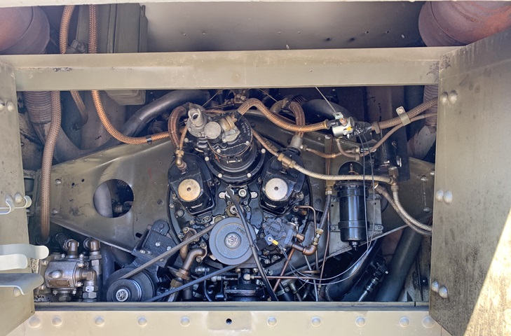
The engine can be seen here installed with the access doors open.
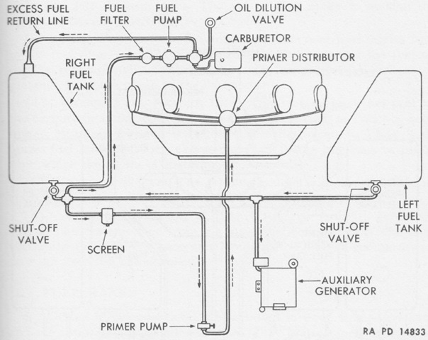
The Continental engine's fuel system is diagrammed in this sketch. The tanks were interconnected, but the right tank needed to be used until about 75% empty, as if both tanks were used the excess fuel return line could potentially overfill the right tank. (Picture from TM 9-727 Light Tanks M3A1 and M3A3.)
Transmission removal involved removing the front sloping armor after unfastening the slotted-head cap screws, hex-head bolts, and hex-head nuts that secured the plate to the hull. (Picture from TM 9-727 Light Tanks M3A1 and M3A3.)
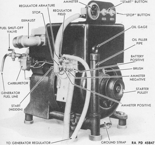
The auxiliary engine was a single-cylinder, 4-cycle, air-cooled, gasoline unit that operated a 6-pole, 12-volt, 750-watt DC generator. (Picture from TM 9-727 Light Tanks M3A1 and M3A3.)
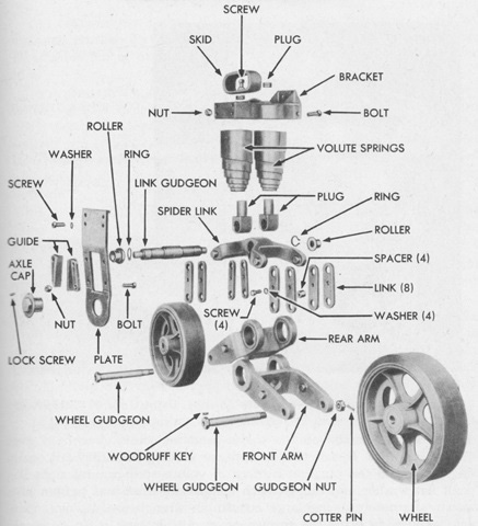
This exploded view shows parts of a bogie assembly. (Picture from TM 9-727 Light Tanks M3A1 and M3A3.)
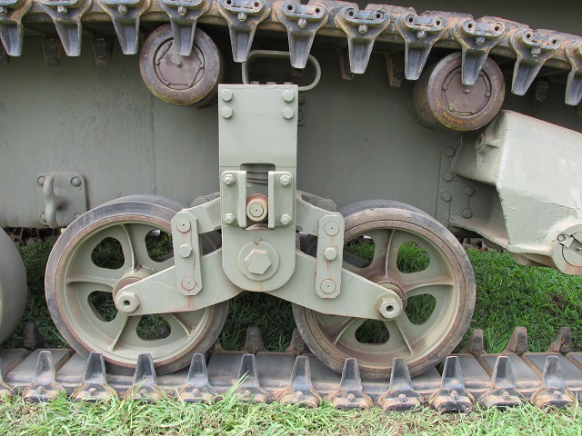
A fully-assembled bogie is shown here, as well as two track support rollers. There is a hook assembly between the suspension bogies on each side of the hull. The idler wheels were sprung by a horizontal volute spring to maintain track tension.
When rubber tracks were fitted, the trailing idler originally was an all-metal wheel, while when steel tracks were mounted the idler was to have a rubber facing. By late 1943, however, the steel wheels were being replaced by rubber-faced wheels no matter what tracks were mounted. (Picture from TM 9-727 Light Tanks M3A1 and M3A3.)

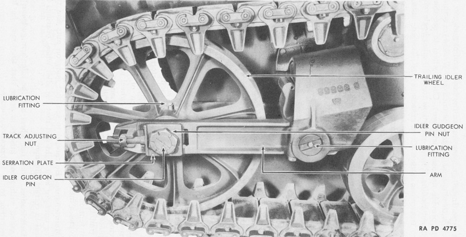
The adjustment mechanism for the trailing idler wheel is shown here. Once the large flat gudgeon nuts were loosened, the track adjusting nuts near the ends of the idler arm could be turned to adjust the idler wheel's position.
The fixed fire extinguisher secured to the bulkhead was a 10lb (4.5kg) unit that was used to suffocate fires in the engine compartment. A 5lb (2.3kg) portable extinguisher was strapped to the left side of the propeller shaft housing. (Picture from TM 9-727 Light Tanks M3A1 and M3A3.)
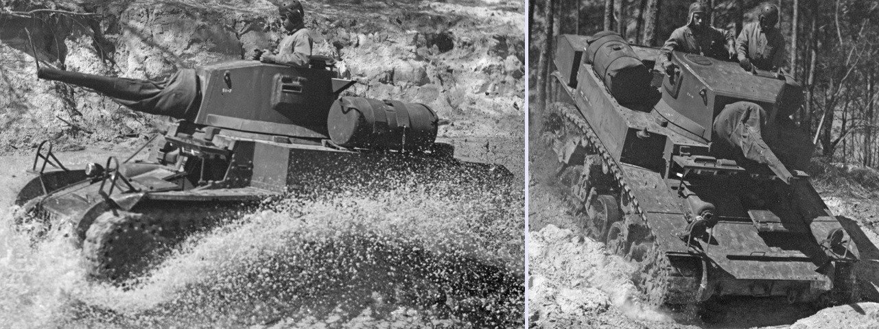
To help alleviate the M3's dismal range, two 25gal (95L) jettison fuel tanks were mounted on the rear hull beginning in late 1941. The tanks were plumbed into the engine's fuel supply via an automatic fuel transfer coupling and a self-sealing hose; a self-sealing cover also helped protect the jettison tanks. The tanks were released from the vehicle by a cable in the fighting compartment, and the vehicle's range was increased by nearly 100%. These men were engineers in the Marine Corps's 51st Composite Battalion taking part in tank training. (Pictures taken in March 1943 by Roger Smith; available from the Library of Congress.)
The entirely new hull design of the M3A3 Stuart can be discerned here. The drivers were provided with direct vision ports in the hull front, and these were closed with the plugs as seen. The frames in front of the driver are for mounting the foul weather driving hood, and a ventilator is positioned between the drivers. (Picture from Tank Data, vol. 1.)
The drivers' and turret doors are open on this machine. Although the assistant driver now had his own hatch, the drivers' doors could foul on the 37mm gun if the turret was traversed to an unlucky angle in an emergency. (Picture from TM 9-2800 Standard Military Motor Vehicles.)
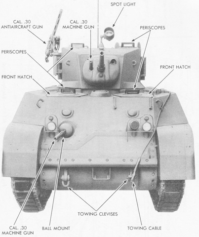
Details found on the front of the tank are labeled here. (Picture from TM 9-727 Light Tanks M3A1 and M3A3.)

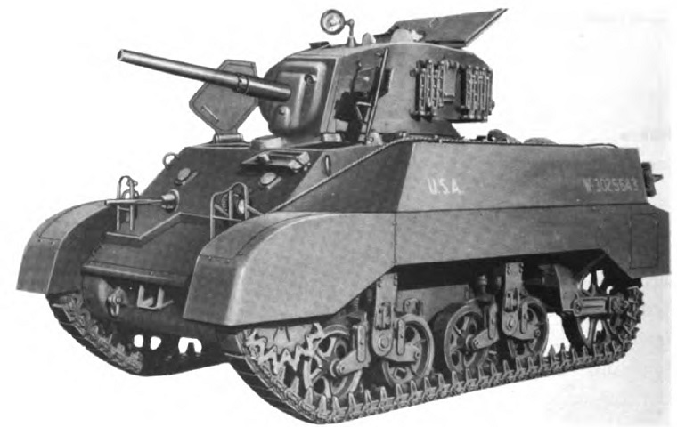
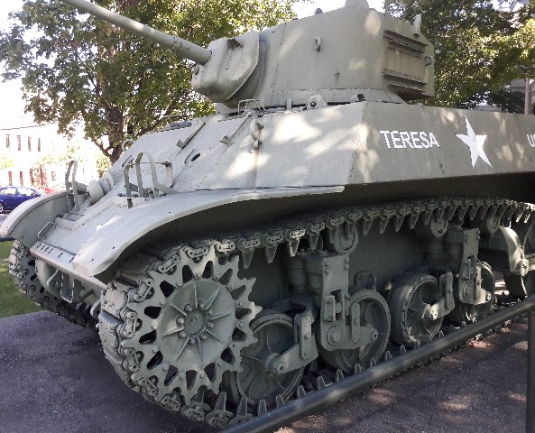
This view illustrates the sloping hull sides that also differentiate this model from the M5. The weapons on this tank are replicas, and there is a plate welded between the gun shield and the hull ventilator.
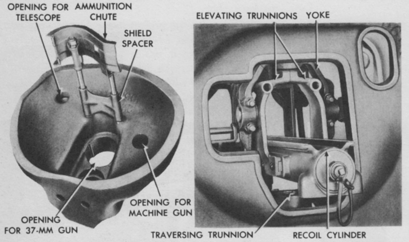
The gun shield is shown removed from the turret in the left image, and the turret front without the gun shield is on the right. The shield attached to the trunnion yokes and moved as part of the gun. (Picture from TM 9-250 37-mm Gun M6, Mounted in Combat Vehicles.)
Transmission removal now required the disassembly of more armor pieces, including the upper section front armor plate, two triangular sections of side armor, and the lower front armor plate. (Picture from TM 9-727 Light Tanks M3A1 and M3A3.)
The flat rear deck helps to differentiate it from the M5 Stuart, and the new turret features the radio bustle which was later incorporated into the turret of the M5A1. Track grousers are stored on the turret, and an antenna mount is present on the turret rear. Sandshields and a rear stowage box are mounted on this tank. (Picture from Development of Armored Vehicles, volume 1: Tanks.)
This image shows rear stowage. (Picture from TM 9-727 Light Tanks M3A1 and M3A3.)
The lower rear hull was virtually identical to the previous generations, from the engine access doors to the continued use of riveting. Above the doors, the increased width of the sponson armor can be compared with earlier tanks, which allowed the air cleaners to be inside the armor envelope and provided space for extra fuel tanks.
The tank is seen here from above. (Picture from TM 9-727 Light Tanks M3A1 and M3A3.)
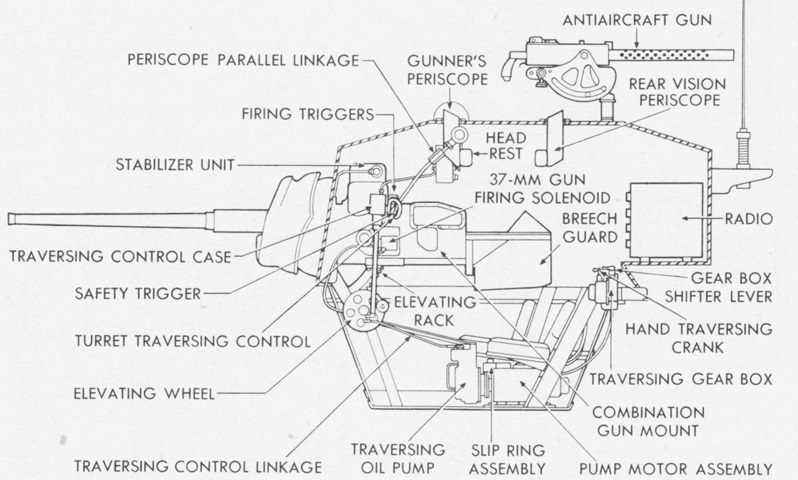
A cross-sectional view of the M3A3 is shown here. Due to the propeller shaft, the turret traverse mechanism was mounted to the floor of the turret basket. (Picture from TM 9-727 Light Tanks M3A1 and M3A3.)
Ammunition stowage is detailed in this sketch. The thirty 37mm rounds in the right sponson were omitted in command tanks. (Picture from TM 9-727 Light Tanks M3A1 and M3A3.)
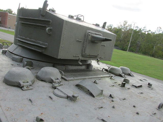
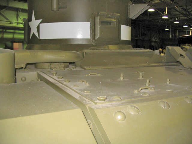
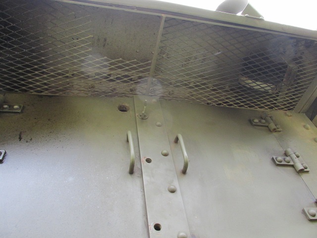
The large armored covers for the fuel fillers can be seen on either side of the air intake grille, and pioneer tool stowage occupied the rear portion of the engine deck. In front of the left-side fuel fillers is the release handle for the fixed fire extinguishers, and behind them is the armored flap that covered the opening to the engine air intake. If a backfire or other event caused a fire in the intake, this flap could be opened so that a portable fire extinguisher could be used to douse the fire. The removable plate in the turret rear eased removal of the 37mm gun. The tank's radio was mounted just inside the plate, and the mount for the radio mast base is attached to the top of the removable plate.
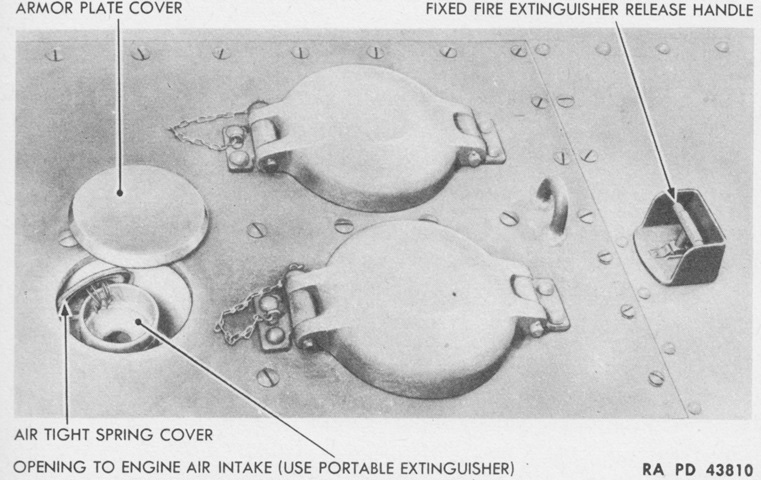
Seen from the opposite angle compared to the image above, the opening to the engine air intake for portable fire extinguisher discharge is shown ready for use. The portable extinguisher was moved in the M3A3 to the front hull at the assistant driver's right. (Picture from TM 9-727 Light Tanks M3A1 and M3A3.)
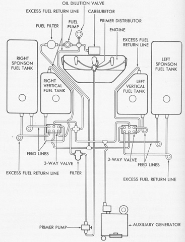
This is a schematic of the fuel system, showing the two additional horizontal sponson fuel tanks compared to earlier generations. The valving allowed fuel to be consumed from a single tank or from two tanks, one on each side. (Picture from TM 9-727 Light Tanks M3A1 and M3A3.)
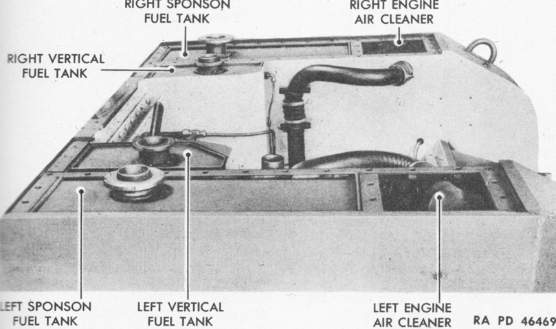
The vehicle is facing to the left in this image. The fuel tanks were mounted in wooden-lined pockets on wooden spacers, and were attached to the hull via a nut on the filter. The under-armor air cleaners are also shown here. (Picture from TM 9-727 Light Tanks M3A1 and M3A3.)
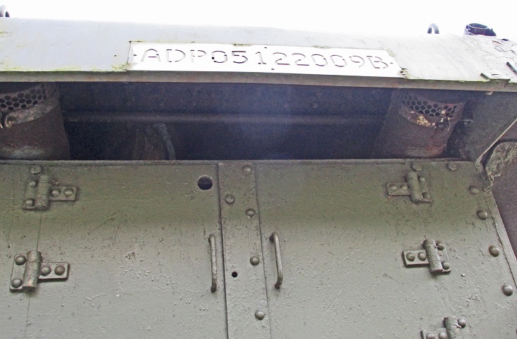
A closer view of the engine access doors is provided here, highlighting their similarity with those found on previous tanks.
Looking under the rear armor plate, the engine exhaust outlets are also found in the familiar spots.
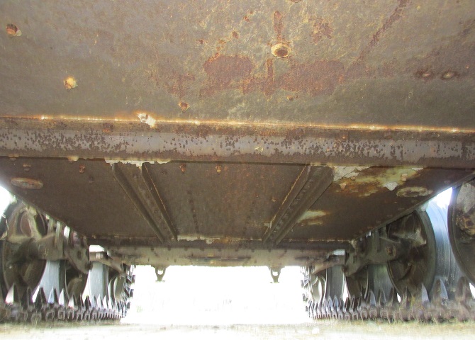
The underside of the hull is shown here, looking toward the rear of the tank. Longitudinal and transverse reinforcement angles can be seen.
The driver's instruments were now all located in a single panel to his front, which was also in view of the assistant driver. (Picture from TM 9-727 Light Tanks M3A1 and M3A3.)
A closeup of the instrument panel is provided in this picture. (Picture from TM 9-727 Light Tanks M3A1 and M3A3.)
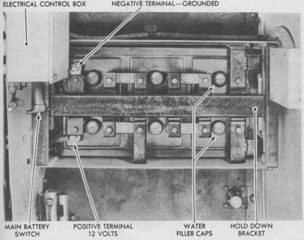
In the M3A3, the battery compartment was moved from the right sponson location of earlier tanks to behind the driver's seat. Battery access was only possible via the driving compartment. (Picture from TM 9-727 Light Tanks M3A1 and M3A3.)
The assistant driver had neither driving controls nor a sight for his machine gun, which was aimed via tracers and impacts. (Picture from TM 9-727 Light Tanks M3A1 and M3A3.)
In addition to the periscope M4 and telescope M40, the gunner in the M3A3 was provided with a telescope M70D or M54. The M54, a 3x erect-image type with a 12°19' field of view, is shown here. (Picture from TM 9-727 Light Tanks M3A1 and M3A3.)
The reticle for the M54 was similar to that of the telescope M40. (Picture from TM 9-727 Light Tanks M3A1 and M3A3.)
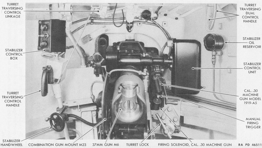
This picture shows details of the combination gun mount M23 installed in the turret. Note the sighting telescope. (Picture from TM 9-727 Light Tanks M3A1 and M3A3.)
The new turret is sectioned in this drawing, showing the utility of the new bustle in allowing the radio to be mounted. In contrast to the combination gun mount M23, the M44 featured a front periscope linkage bracket instead of the M23's front telescope mounting bracket. The telescope in the M44 was also mounted in a higher position. (Picture from TM 9-727 Light Tanks M3A1 and M3A3.)
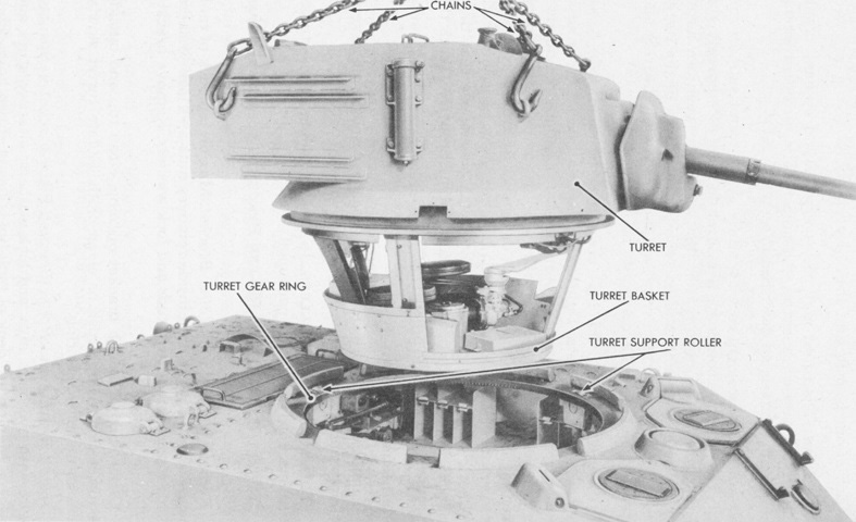
The turret is shown in the process of being removed, revealing the turret basket and crew positions. (Picture from TM 9-727 Light Tanks M3A1 and M3A3.)
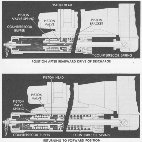
The hydrospring recoil system of the gun mount M44 is diagrammed in action. When fired, the force exerted on the breechblock by the propellant gases drove the gun to the rear by about 8" (20cm). The piston attached to the gun slowed the rearward motion via the resistance of the recoil oil as the oil flowed through holes opened by pressure exerted on the piston valve and also into the hollow portion of the piston rod that was uncovered as the rod moved away from the tapered counterrecoil buffer. The counterrecoil spring helped arrest the rearward motion and then return the gun to battery. (Picture from TM 9-250 37-mm Gun M6, Mounted in Combat Vehicles.)
A closer look at the hydraulic and electrical equipment in the turret basket is provided here. (Picture from TM 9-250 37-mm Gun M6, Mounted in Combat Vehicles.)
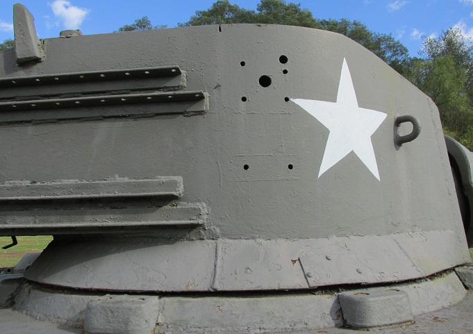
The holes for mounting the M20 antiaircraft machine gun mount are visible on the right side of the turret, along with the bilevel racks for track grouser stowage.
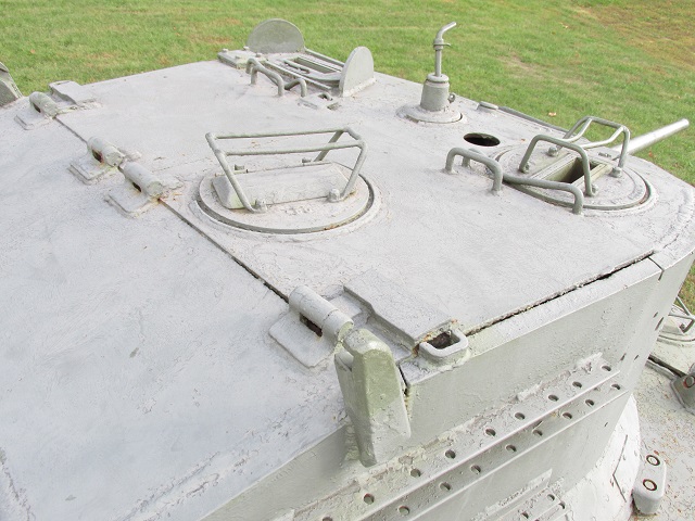
Looking at the top of the turret, the commander's two rotating periscopes can be seen on the right, and the gunner's fixed periscope can be seen in front of the far hatch. The mount for the spotlight remains on the turret roof front and center, although the light itself is absent.
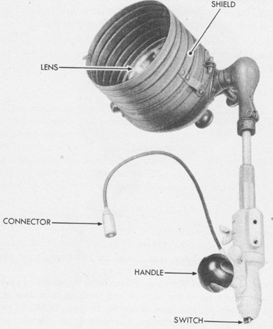
The spotlight is shown here mounted on its operating handle. It could also be removed and attached to a pistol grip with an integral 10-foot (3m) extension cord. The pistol grip had a signaling trigger-type switch so the commander could use the lamp as a signal light. (Picture from TM 9-727 Light Tanks M3A1 and M3A3.)
The driver's direct vision plug is missing from this vehicle, showing the diameter of the vision port beneath. (Picture courtesy Mark Anthony Cabrera, DO.)
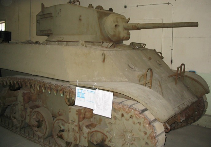
The tracks on this example are in better condition, and it has (familiar) references conveniently ziptied to the front fender. The plugs for the drivers' vision ports are in place on this tank.
