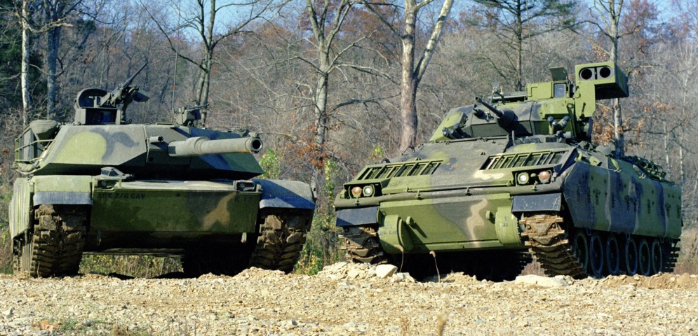
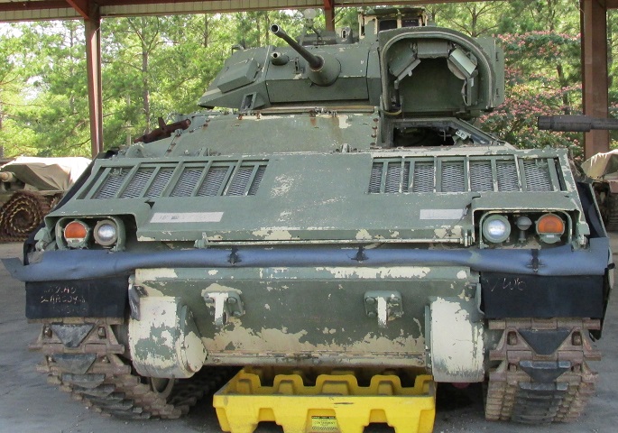
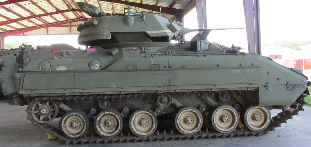
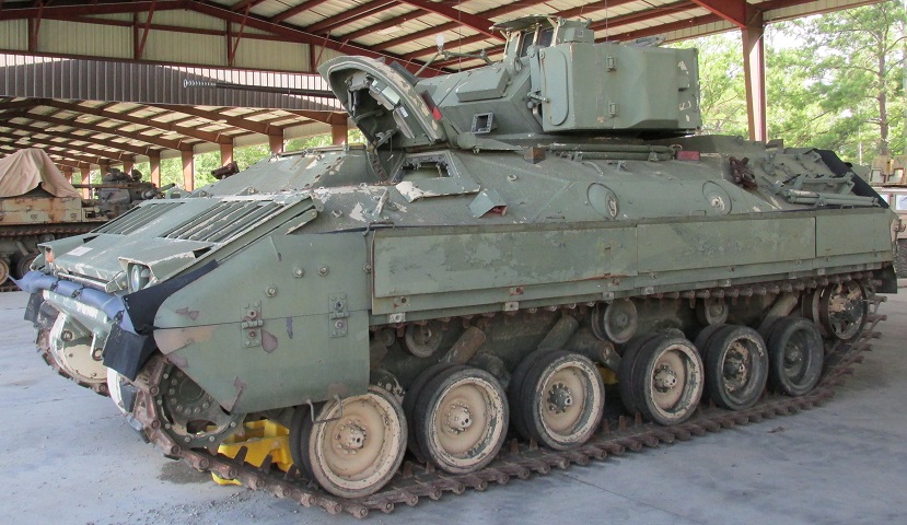
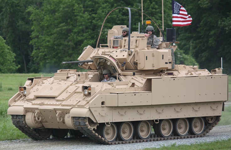
Infantry Fighting Vehicle M2 Bradley at Ft. Knox, Kentucky.
There is a distinctive space between the first three and last three road wheels on this M2 Bradley. The 7.62mm coaxial machine gun protrudes from the turret to the right of the 25mm chain gun, and the twin TOW missile launcher is positioned on the left side of the turret. The weapons' sights are contained in the armored box on the turret roof. The driver is seated in the front left, with the engine to his right, and both are behind the large folding trim vane. It was necessary to include vision slots in the trim vane so that the driver could see where he was going when the device was erected. The Bradley was also used by Cavalry units for reconnaissance as the M3, and some scouts were displeased with the vehicle's large size, which is illustrated here compared to this M1 Abrams tank. (Picture taken 1 Jan 1983 by Steve Catlin; available from the Defense Visual Information Center.)
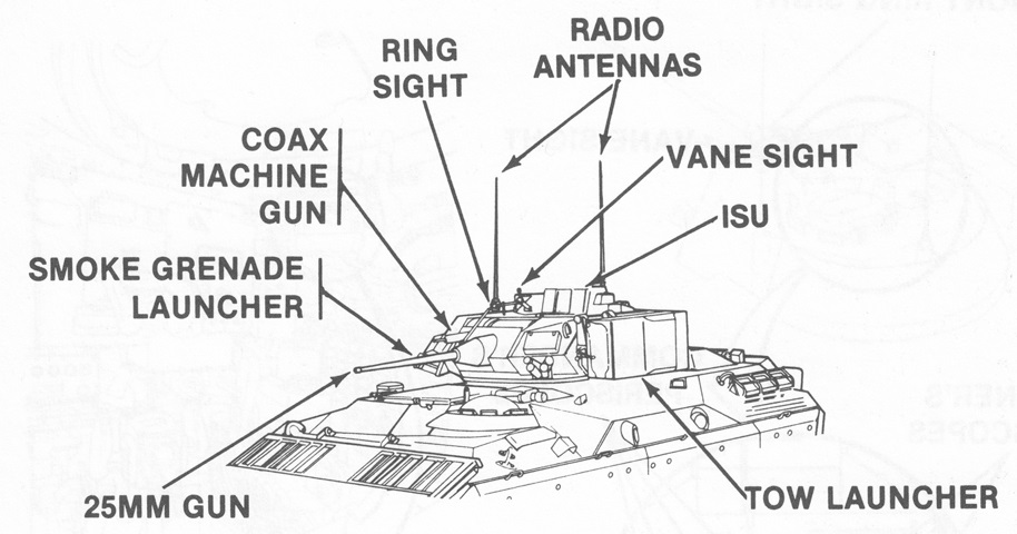
Turret details are labeled in this sketch. The ISU was the integrated sight unit that provided day and night vision to the gunner at either 4x or 12x magnification, with a relay sight extended to the commander's position. (Picture from TM 9-2350-252-10-2 C6.)
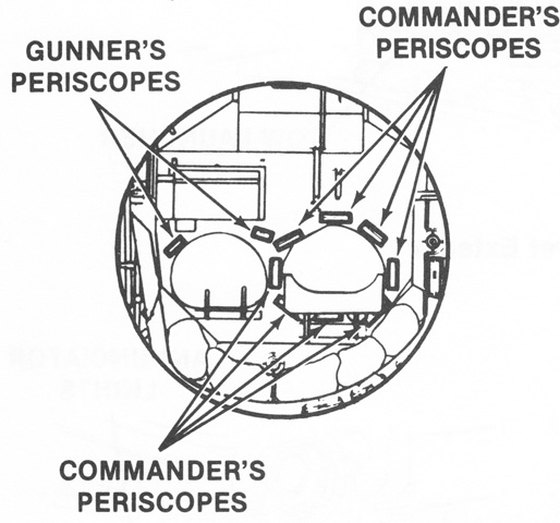
The commander was provided with eight periscopes for 360° vision while under armor, and the gunner could use two periscopes to see to either side of the ISU housing. (Picture from TM 9-2350-252-10-2 C6.)
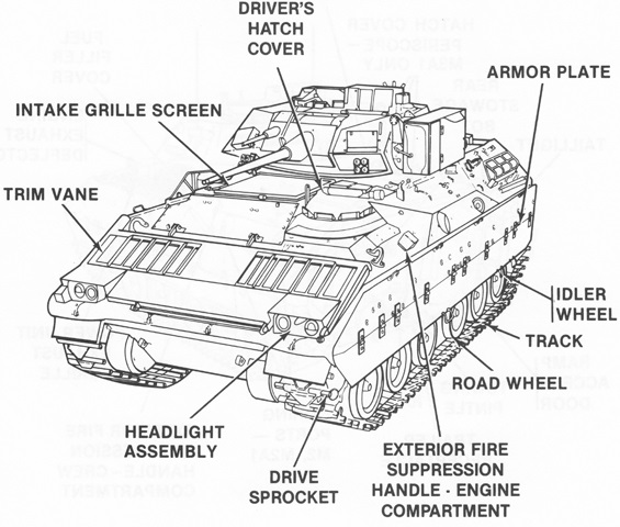
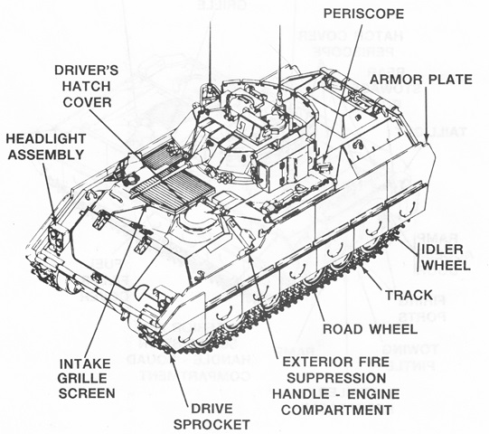
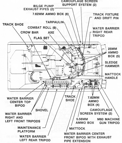
Details of the hull are labeled in this sketch. (Picture from TM 9-2350-252-10-1 C1.)
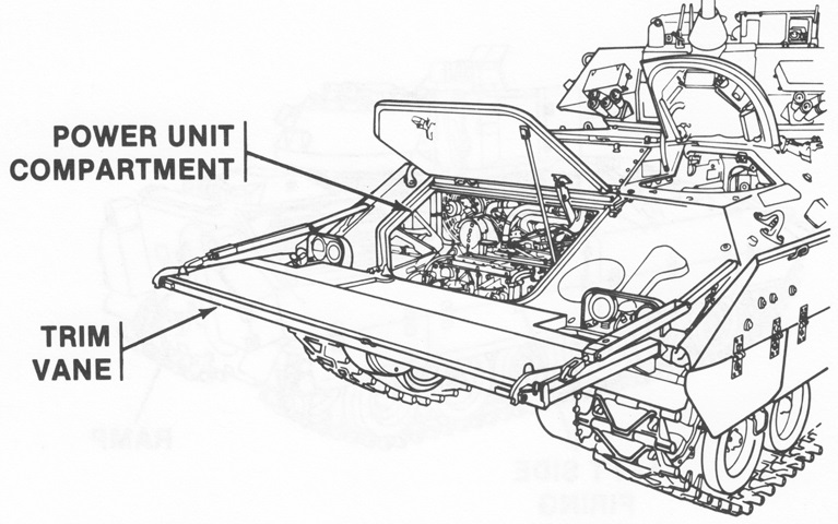
When the trim vane was lowered to the completely horizontal position, it was able to be used as a work platform for the power unit compartment. (Picture from TM 9-2350-252-10-1 C1.)
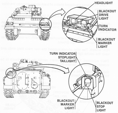
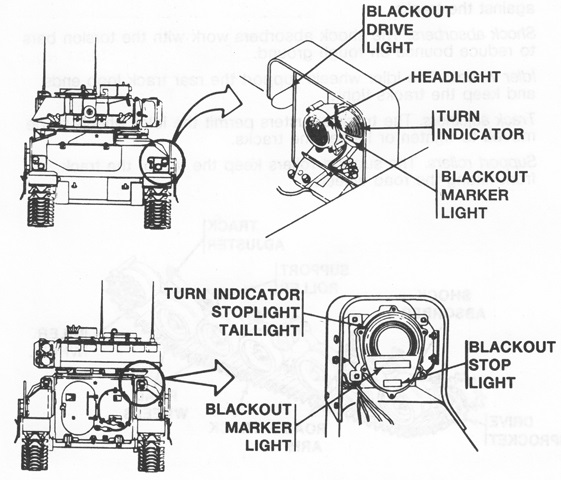
The external lighting assemblies are detailed in this drawing. (Picture from TM 9-2350-252-10-1 C1.)
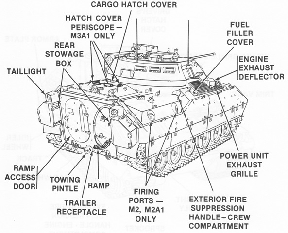
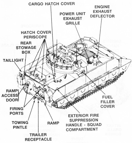
The rear of the vehicle is shown here. (Picture from TM 9-2350-252-10-1 C1.)
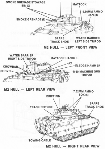
External stowage is detailed in these diagrams. (Picture from TM 9-2350-252-10-1 C1.)
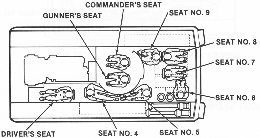
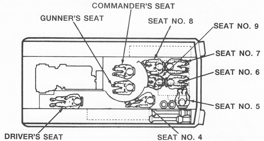
The positions of the vehicle crew and dismount squad can be seen in this drawing. The powerplant is to the driver's right, and missile reloads are stowed at the left rear corner of the hull. (Picture from TM 9-2350-252-10-1 C1.)
The driver's hatch is open on this vehicle, allowing a view of his periscopes.
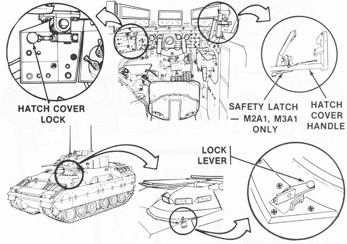
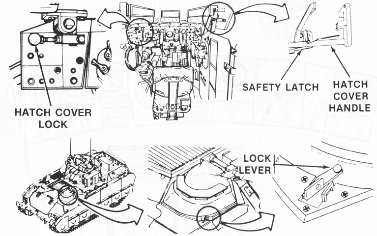
The controls for the driver's hatch are illustrated here. The hatch cover lock locked or unlocked the hatch from inside the vehicle; likewise the hatch cover handle controlled the positioning and closing of the hatch from the inside. A safety pin secured the hatch cover in place on the M2 and M3, while a safety latch performed this function in the M2A1 and M3A1. The lock lever locked and unlocked the hatch from the outside. (Picture from TM 9-2350-252-10-1 C1.)
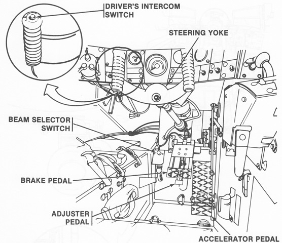
The layout of the driver's station is seen in this image. The beam selector switch toggled between the high and low headlight beams, and the adjuster pedal let the driver position the brake pedal to his liking. (Picture from TM 9-2350-252-10-1 C1.)
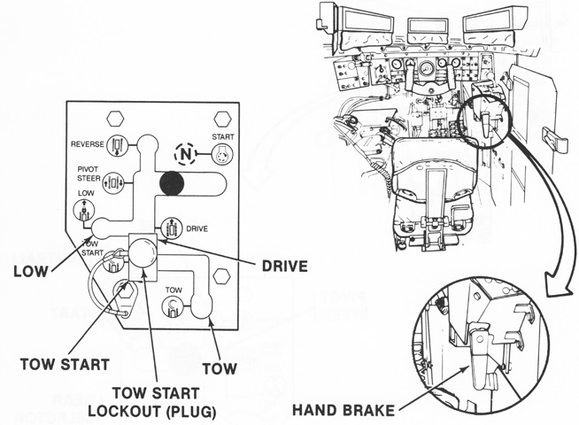
The gear selector was to the driver's right. Neutral disengaged the transmission from the engine, but not from the drive train. The start position engaged the engine starter. Pivot steer allowed the tracks to turn in different directions in order to turn the vehicle on its own center. The tow start position was used when starting the vehicle engine by having it towed by another machine. The tow start lockout (plug) prevented the gear selector from being moved to tow start from drive while the vehicle was being driven. Finally, the tow position was used when the vehicle was being towed. The parking hand brake was below the transmission gear selector; an interlock was installed between the hand brake and the gear selector. (Picture from TM 9-2350-252-10-1 C1.)
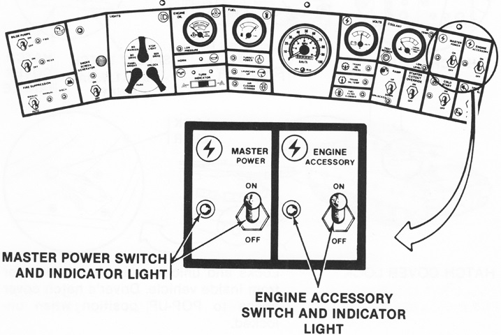
The driver's instrument panel stretched across the compartment above the steering yoke. The master power and engine accessory switches and indicator lights are labeled; directly under these were the cold start switch and indicator light to the left and the tone cancel/push to test switch to the right. The cold start switch was used to heat the engine glow plugs when the temperature was +40°F to -25°F (+4°C to -32°C). When the tone cancel/push to test switch was toggled up, it cancelled the warning tone being emitted; when pressed down it tested all instrument panel indicator lights except that for turret power. The dial to the left of the master power switch was the engine coolant temperature gage, and below this to the left was the switch to raise or lower the ramp, and to the right was the starter cutout override switch to allow the engine starter to crank longer in colder temperatures. The dial to the left of the coolant temperature gage was the voltmeter. Below this, from top to bottom, was the transmission oil pressure warning light, the transmission oil temperature warning light, and the fuel filter clogged warning light. The large dial to the left of the voltmeter was the speedometer, with integral odometer and high beam indicator light. The dial to the left of the speedometer was the fuel gage. Two interconnected fuel tanks were mounted: the upper in the right sponson beside the turret, and the lower under the turret. The gage provided the reading for the lower fuel cell. Below this, from top to bottom, was the turret power indicator light; the launcher up indicator light, which flashed when the TOW missile launcher was erected and the vehicle was moving at least 3mph (5kph); and the air cleaner clogged warning light. The dial to the left of the fuel gage was the engine oil pressure gage. Below this was the horn button, and below the horn was the turn indicator/hazard light switch. The switch in the lower right to the left of the engine oil pressure gage was the lock switch for the driving light switch. This had to be held in the unlock position to move the driving light switch to any position besides that activating the blackout marker lights. The driving light switch was the top switch, and the panel lights brightness and parking light switch was to the lower left. To the left of the light switches was the smoke screen generator switch. To the left of the smoke generator switch, from top to bottom, were the forward bilge pumps switch, rear bilge pumps switch, and the fire suppression switch. (Picture from TM 9-2350-252-10-1 C1.)
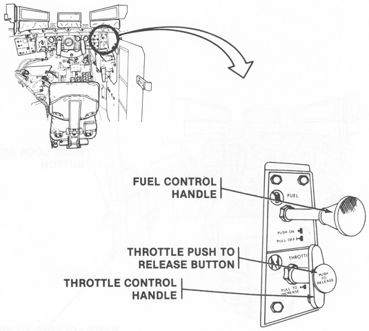
To the right of the instrument panel was the fuel and throttle control panel. The fuel control handle started and stopped fuel flow to the engine, and the hand throttle and its release were positioned below. (Picture from TM 9-2350-252-10-1 C1.)
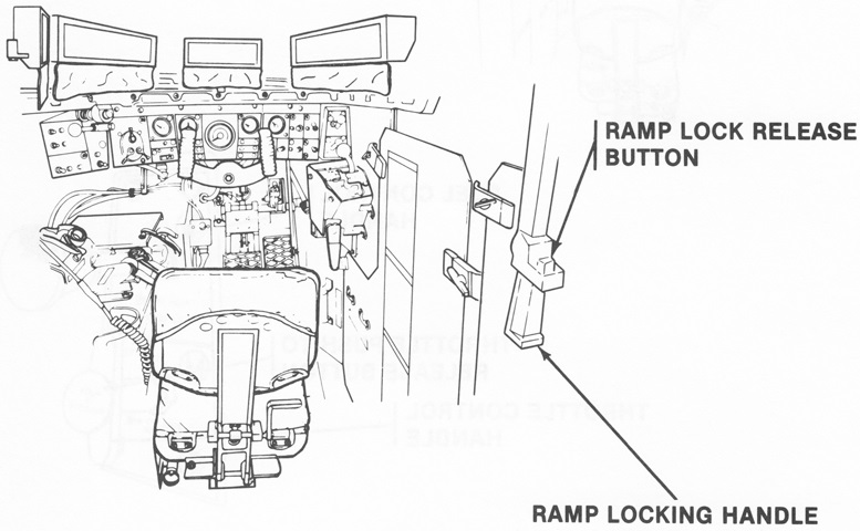
To the driver's right rear, the ramp locking handle locked the rear ramp in the raised position or unlocked it for lowering. The release button was pressed to actuate the handle. (Picture from TM 9-2350-252-10-1 C1.)
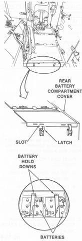
The vehicle batteries were under the floor of the tunnel behind the driver's seat. The number 4 squad seat would have to be stowed before the batteries could be checked or replaced. (Picture from TM 9-2350-252-10-1 C1.)
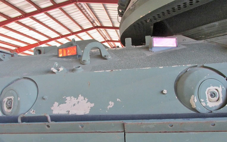
Some panels of the spaced armor skirt have been raised, and details of the suspension can be seen. The engine exhaust deflector is on the upper side hull between the forward second and third road wheels, and stowage racks for 7.62mm ammunition cans line the outside of the inward-sloping turret bustle stowage rack. An antenna mount is present in the middle of the turret's right side.
A closer view of the two right-side firing ports is provided here. Periscopes are embedded in the upper hull, and the rear roof hatch can be seen in the background. The turret bustle stowage rack featured drainage holes in its underside.
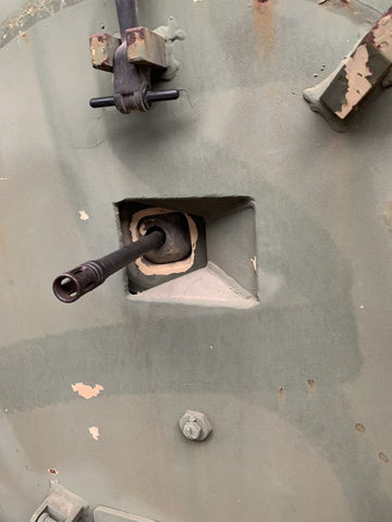
The same firing ports as above are shown with M231 firing port weapons installed. The external handle for the fixed fire extinguisher is seen under a guard ahead of the forward firing port. The armor skirt panels are still raised.
The right-side firing port in the rear ramp is highlighted in this picture, and it also has an M231 present.
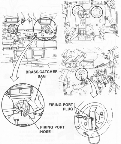
The interior sides of the firing ports are shown in this drawing. The ports were closed with a plug, and the brass catcher bag was attached to the firing port weapon when installed. The hose connected the brass catcher bags to the firing port vent system. (Picture from TM 9-2350-252-10-1 C1.)
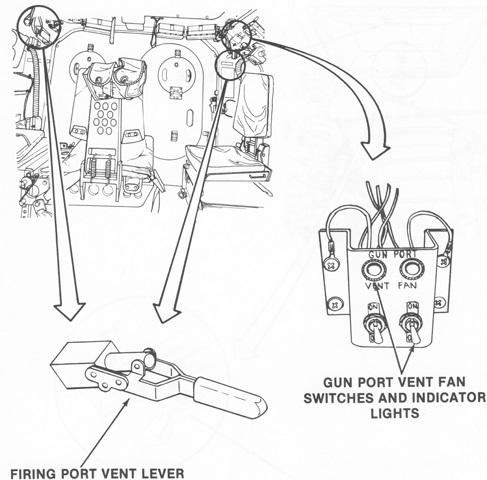
Gases produced by the firing port weapons were expelled to the outside via a vent and fan system that utilized the hoses connected to the brass catcher bags. (Picture from TM 9-2350-252-10-1 C1.)
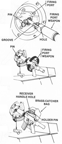
After removing the plug from the firing port, the M231 firing port weapon was inserted into the port, and the pin on the port was aligned with the groove on the barrel of the gun. The gun was then screwed in until the pin locked into the hole on the weapon. The brass catcher bag was attached to the receiver handle via a holder pin. (Picture from TM 9-2350-252-10-1 C1.)
The skirt panels are raised on the opposite side of the vehicle as well.
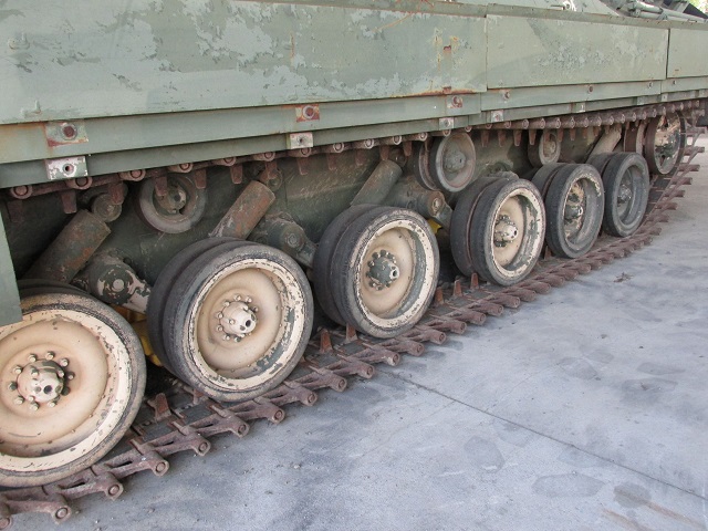
Details of the running gear are provided here, including the location of the shock absorbers and the two single and one dual track return rollers. The spaced armor on the inside of the raised skirt panels is also visible.
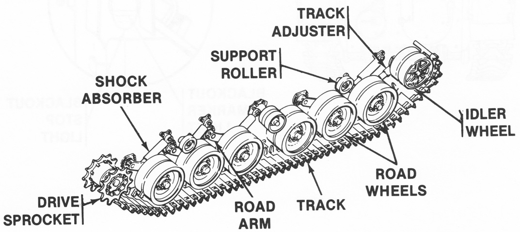
Further details and nomenclature of the suspension are drawn in this picture. (Picture from TM 9-2350-252-10-1 C1.)
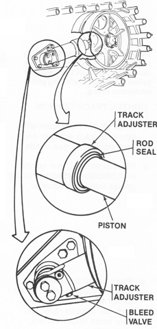
Track tension was measured at the rear support roller. It was to be able to turn freely, but an index finger was not to be able to pass between the roller and the track. To tighten track tension, grease was pumped into the lubrication fitting on the front of the idler wheel track adjuster from a lubrication gun. The bleed valve on the side of the track adjuster allowed grease to be removed when track tension was loosened. (Picture from TM 9-2350-252-10-1 C1.)
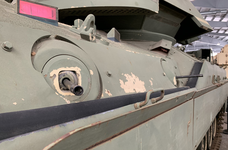
The firing ports and periscopes on the left side of the vehicle are shown here.
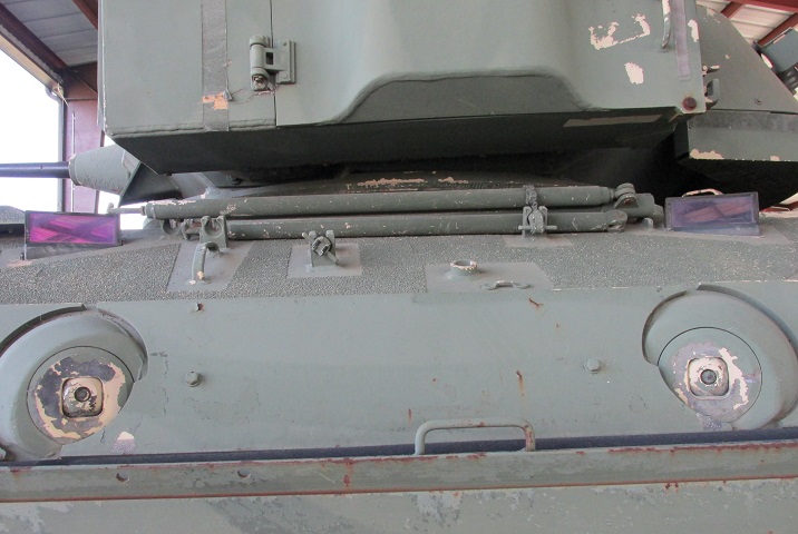
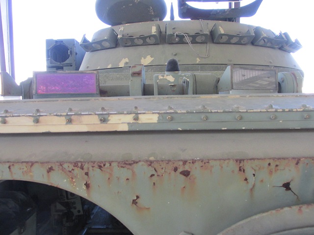
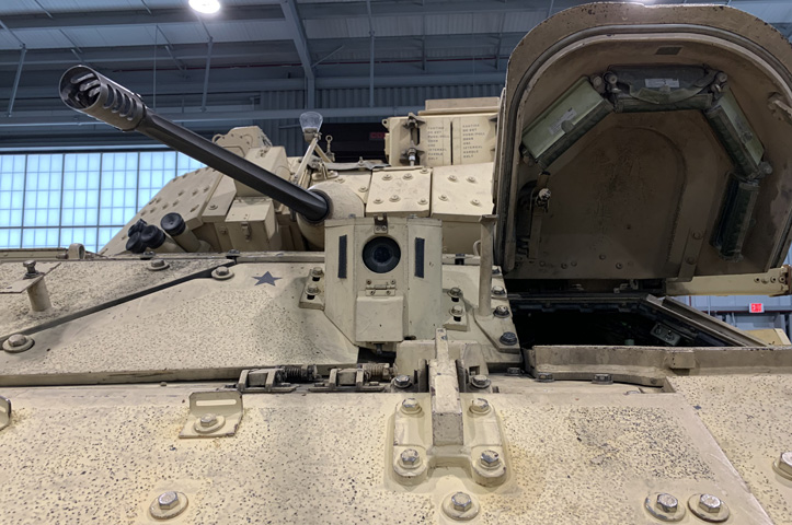
The smoke grenade launchers are not mounted on this vehicle, but the stowage box for spare grenades remains on the turret front. When the TOW launcher is raised, the plate covering the front falls below.
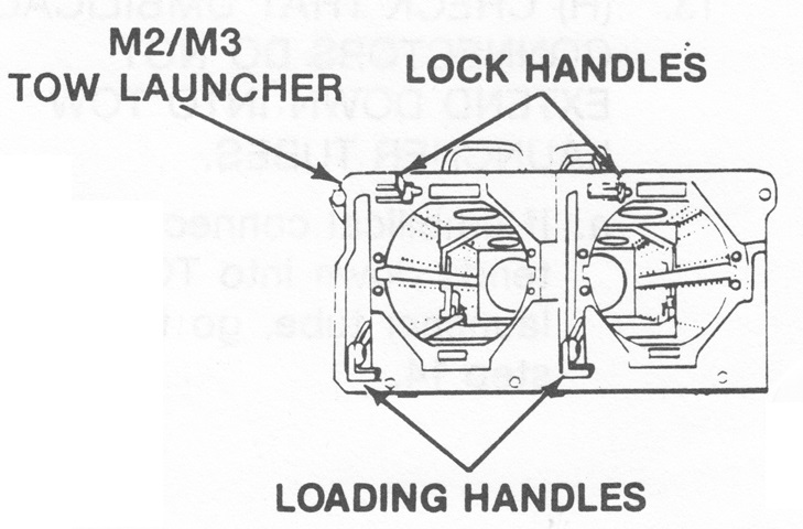
In contrast to later versions, the missile launcher of the M2 and M3 had two lock and loading handles. (Picture from TM 9-2350-252-10-2 C6.)
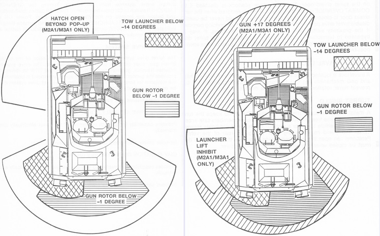
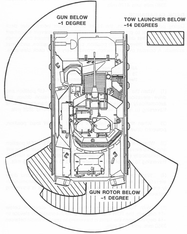
Interlocks were provided that prevented the firing of the weapons under the above conditions. As illustrated on the left, if the gun rotor was trained over the rear deck (2525 to 3825 mils) at -1° elevation or below, neither the 25mm gun nor coaxial machine gun would fire. Also, if the cargo or driver's hatch covers were open past the pop-up position, the guns would not fire. The TOW launcher would likewise not fire if aimed over the rear deck (3350 to 4175 mils) at -14° or greater depression, or if the driver's or cargo hatch covers were open past the pop-up position, or if the vehicle was moving at more than 3mph (5kph), or if the ISU was not in its high magnification setting.
Deck clearance control was also incorporated into power turret operation, shown on the right. When the turret was traversed to between 2525 and 3825 mils, the elevation drive would elevate the gun to at least -1° if the cargo hatch was in the closed or pop-up position. The TOW launcher would similarly be elevated to at least -14° when traversed between 3350 and 4175 mils. Power traverse was disabled when the cargo hatch was in the TOW load position. (Picture from TM 9-2350-252-10-2 C6.)
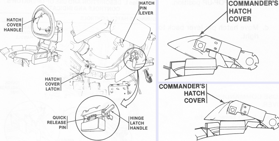
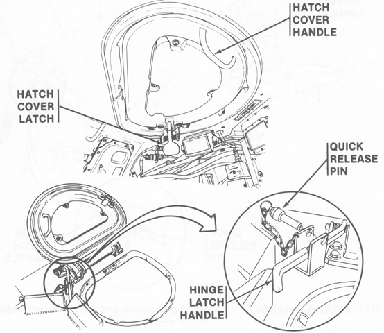
Controls for the commander's hatch are illustrated in the center. In addition to the full open/upright position drawn on the left, the commander could position the hatch cover in the pop-up position shown at the upper right for protected forward vision, or alternatively in the level position at the lower right for protected all-around vision. (Picture from TM 9-2350-252-10-2 C6.)
An overview of the commander's side of the turret is drawn in this picture. The doors to his front concealed the coaxial machine gun. (Picture from TM 9-2350-252-10-2 C6.)
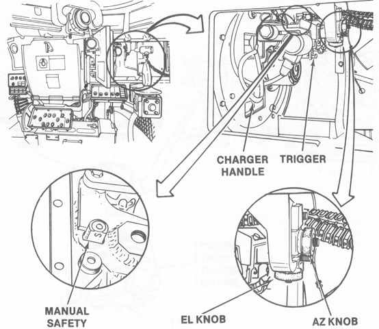
The coax machine gun access doors are open in this image, and the machine gun controls are illustrated. (Picture from TM 9-2350-252-10-2 C6.)
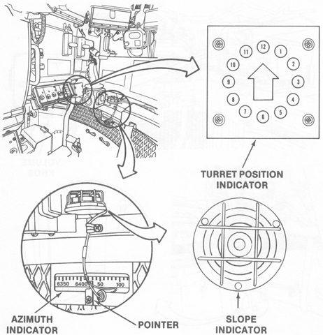
Instruments at the commander's station are shown in this sketch. The slope indicator was used to determine if the ground was too canted to safely fire a TOW missile. If the air bubble was touching the left or right sides of the outer ring, the vehicle would have to find flatter ground. The central square was the "safe zone." (Picture from TM 9-2350-252-10-2 C6.)
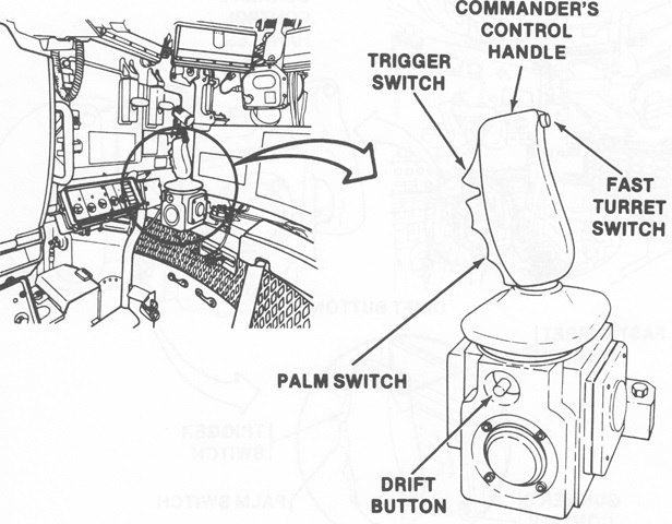
The commander's control handle controlled turret traverse as well as weapon elevation and firing. When the palm switch was squeezed, the turret drive brakes were released, the turret drive was activated, and the gunner's inputs were overridden unless a missile was in flight. The fast turret switch increased the speed of elevation and traverse, and the drift button reduced drift in the turret stabilization system. (Picture from TM 9-2350-252-10-2 C6.)
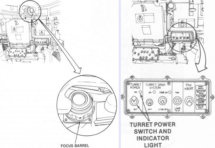
As drawn on the left, a relay sight extended to the commander from the ISU in front of the gunner. This allowed both turret crew to obtain the same sight picture. The turret control box was directly in front of the commander. To the right of the turret power switch and indicator light was the turret drive system switch and indicator light, and then the stabilization switch and indicator light. Next in line was a switch that, when in the up position, manually turned on the gun fans. The gun fans turned on automatically when this switch was in its center position. When the switch was pressed to the down position, all turret indicator lights turned on in order to perform a bulb function check. To the right of this was the TOW abort switch, which cut the command wires to a fired TOW missile and caused it to dive into the ground. On the far right were five annunciator lights: from top to bottom these indicated if the driver's or cargo hatches were open; if emergency battery power was in use, rendering the turret electrical drive nonfunctional; if the weapons were occupying a no-fire zone; if a turret drive select lever was in manual mode; and if the turret drive system was malfunctioning. (Picture from TM 9-2350-252-10-2 C6.)
The gunner's hatch controls are labeled in this drawing. (Picture from TM 9-2350-252-10-2 C6.)
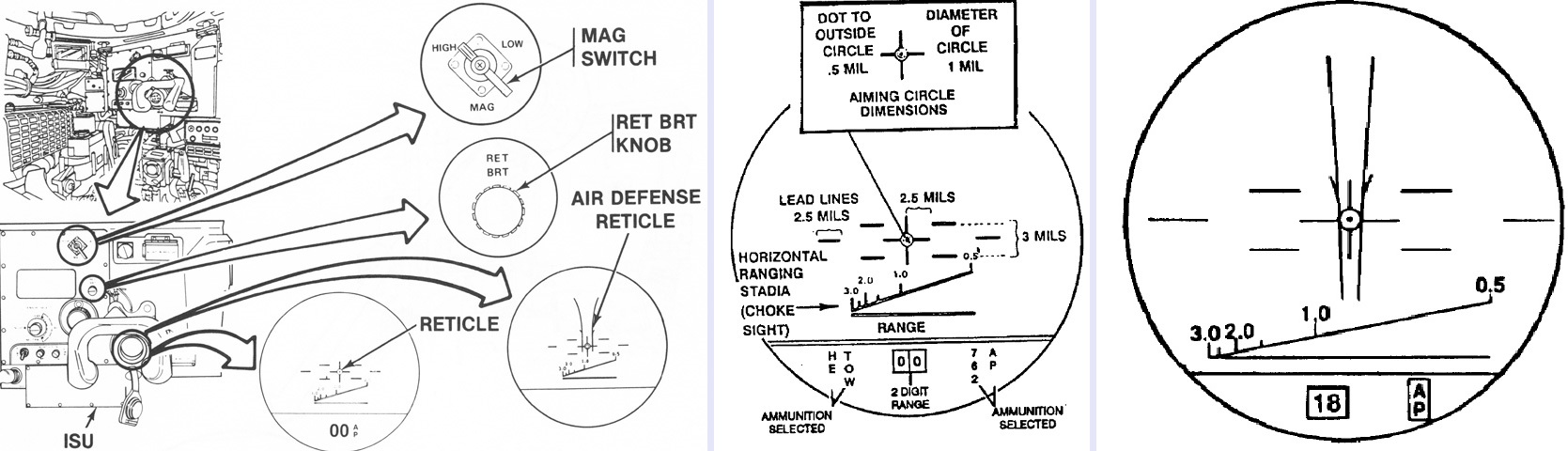
The ISU in front of the gunner is detailed in these sketches. The 1x magnification viewing window is just to the left of the reticle brightness knob, while magnification through the eyepiece could be changed between 4x and 12x. The initial reticle is diagrammed in the center, while some ISUs had the air defense reticle on the right with additional lines for choking the range of a helicopter when the sight was indexed to 1,800m. (Picture from TM 9-2350-252-10-2 C6.)
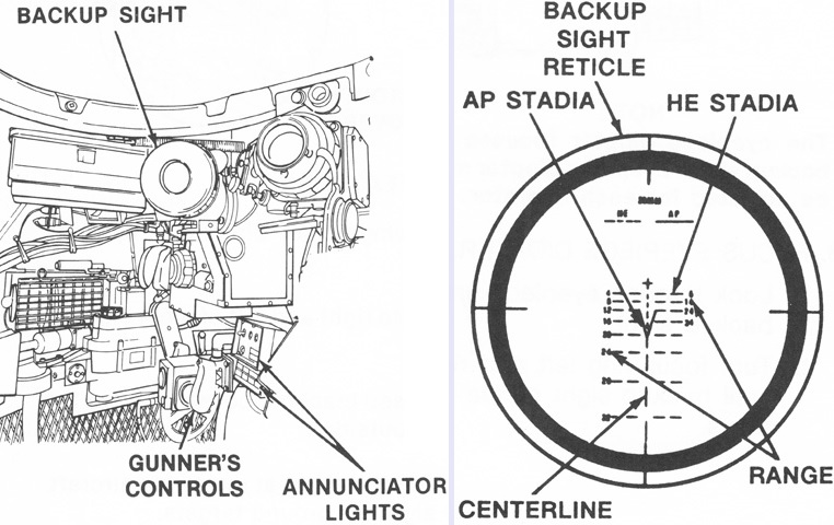
Turret crews of late M2s could also use a backup sight if the ISU was inoperable. It offered 5x magnification with a 10° field of view, and had an elevation arc of -10° to +60°. A flange joint allowed the backup sight to stowed upwards or to be maneuvered to the appropriate position for viewing. (Picture from TM 9-2350-252-10-2 C6.)
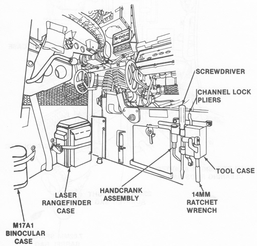
The lower portion of the gunner's side of the turret is sketched here. (Picture from TM 9-2350-252-10-2 C6.)
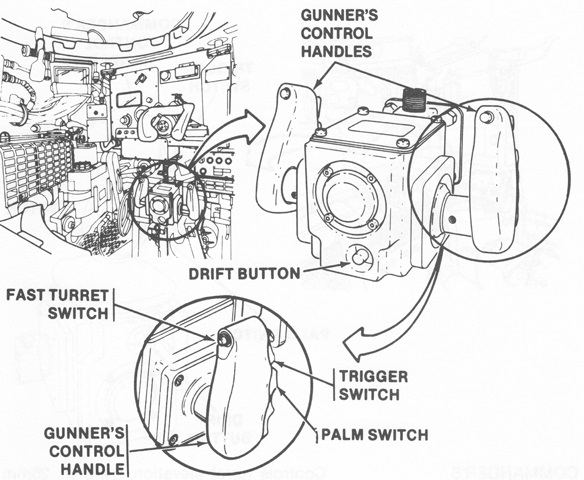
The gunner's handles had similar controls to the commander's. (Picture from TM 9-2350-252-10-2 C6.)
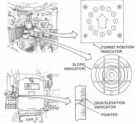
The locations of the gunner's turret position instruments can be seen here. (Picture from TM 9-2350-252-10-2 C6.)
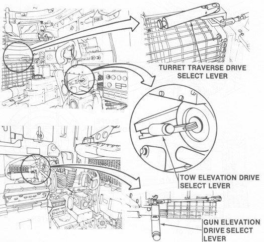
The select lever controls for the turret traverse drive, TOW elevation drive, and gun elevation drive allowed the gunner to choose between power and manual operation for these functions. (Picture from TM 9-2350-252-10-2 C6.)
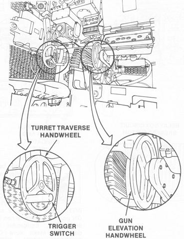
The manual elevation and traverse handwheels were below and outboard of the power control handles. The weapon trigger switch was on the traverse handwheel. (Picture from TM 9-2350-252-10-2 C6.)
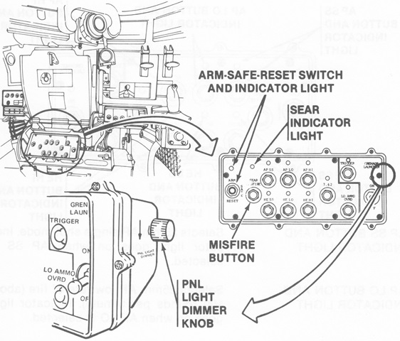
Between the gunner and commander, directly under the 25mm gun guard, was the weapon control box. The reset position of the ARM-SAFE-RESET switch cleared all weapons currently selected. The sear indicator light lit when the 25mm gun bolt was in the sear position and blinked when the bolt was in the misfire position. The misfire button returned the 25mm gun bolt to the sear position after the trigger was depressed when that weapon misfired. To the upper right of the misfire button was the AP SS button and indicator light, which was used to select single-shot 25mm armor-piercing fire. Below this was the HE SS button and indicator for single-shot high-explosive 25mm fire. To the right of the AP SS button was the AP LO button and indicator for low rate armor-piercing fire; below was the HE LO button and indicator. To the right of the AP LO was AP HI for high rate AP fire. Below this of course was HE HI. To the right of the high-rate 25mm buttons was the 7.62 button and indicator to select the coaxial machine gun. To the lower right of the 7.62 button was the LO AMMO OVRD button which allowed the 25mm or 7.62mm guns to fire after the LO AMMO indicator directly above began to flash. Above the LO AMMO indicator light was the trigger button, which fired all eight smoke grenades, and its indicator which lit when this button was pressed. Finally, behind the arrow on the right, was the grenade launcher switch and indicator which powered the smoke grenade launchers on or off. (Picture from TM 9-2350-252-10-2 C6.)
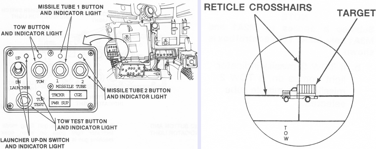
The TOW missile control box is illustrated here. The LAUNCHER UP-DN switch raised or lowered the missile launcher when either position was selected and the palm switches on the commander's or gunner's handles were squeezed. The TOW button selected TOW mode, and the TOW and TOW test indicator lights illuminated when this mode was activated. When the TOW test button was pressed, the TOW test light illuminated for the 12 seconds necessary for the test to be completed. The missile tube buttons selected their respective tubes; the indicator lights lit when the their tubes were selected and flashed when they were empty. The TRCKR light indicated a malfunctioning tracking system; the CGE light alerted to a malfunctioning command and guidance electronics system; and the PWR SUP light reported a malfunction in the missile system power supply. The TOW reticle is drawn on the right, in the process of targeting a truck. The gunner simply kept the crosshairs centered on the target and the missile guidance system worked to have the missile impact that point. (Picture from TM 9-2350-252-10-2 C6.)
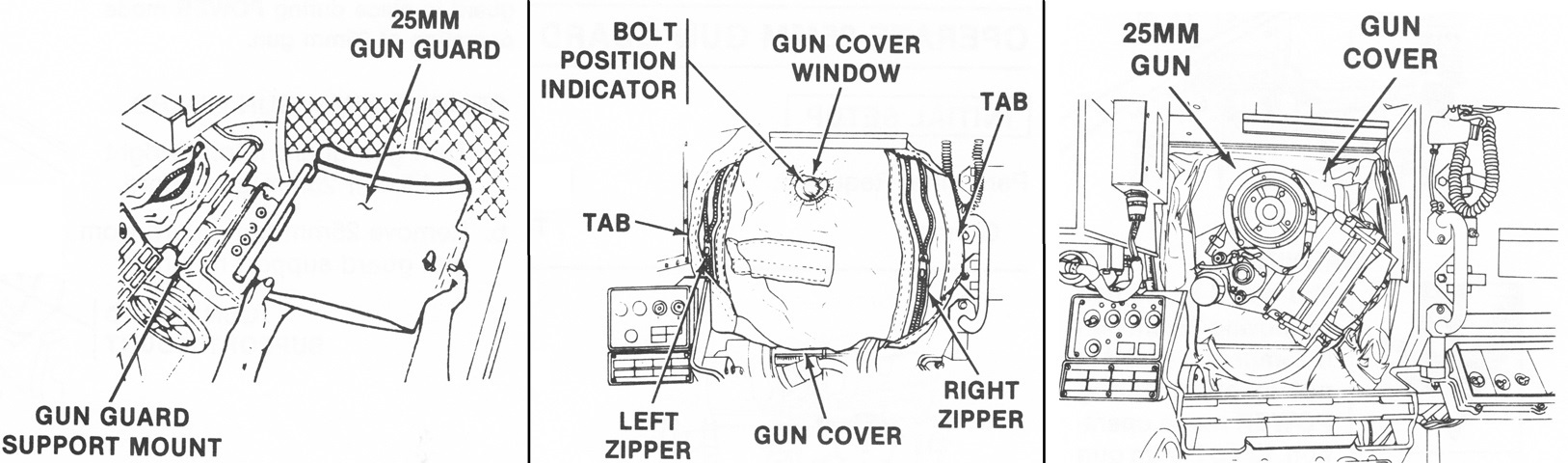
The M242 25mm gun was positioned between the gunner and commander, and access was provided by removing its guard and opening the gun cover. When the trigger was pressed, the sear solenoid was energized and released the sear pin from the master link on the gun's chain. This energized the electric motor driving the track and bolt assembly and feeder. The feeder then placed a round in front of the bolt, the bolt moved forward and locked to the breech, and the sear pin was engaged against the chain safety link. After the round was fired, the bolt was unlocked and the sear pin released, continuing the cycle. The expended casing was extracted by the bolt's rearward travel, and the rotor turned to place the casing into the ejection chute while the next round was positioned in front of the bolt. (Picture from TM 9-2350-252-10-2 C6.)
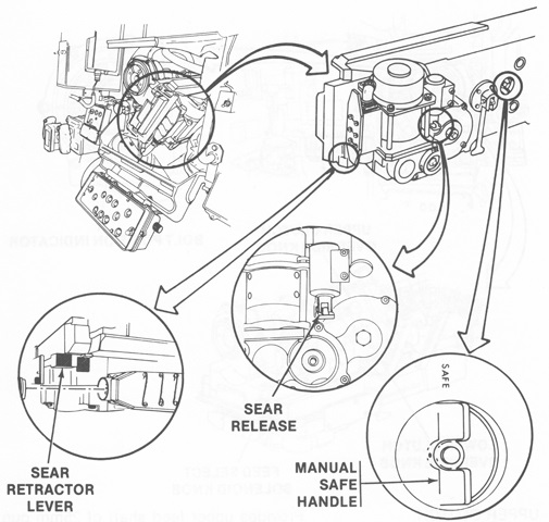
The locations are shown of some controls for the M242. The sear release allowed the sear solenoid plunger to be manually depressed in order to manually cycle the gun. The sear retractor lever allowed the sear solenoid plunger to be manually depressed and locked out in order to manually fire the gun. (Picture from TM 9-2350-252-10-2 C6.)
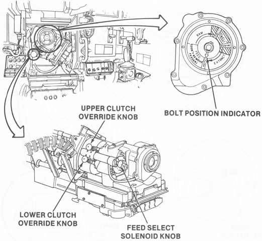
More M242 controls are shown here. The upper and lower clutch override knobs provided the upper and lower feed shafts, respectively, with a manual release so that they could be rotated backwards during unloading. The feed select solenoid knob allowed manual selection of AP or HE ammunition. (Picture from TM 9-2350-252-10-2 C6.)
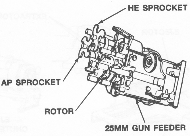
The 25mm gun feeder is shown here with the sprockets for AP and HE ammunition. (Picture from TM 9-2350-252-10-2 C6.)
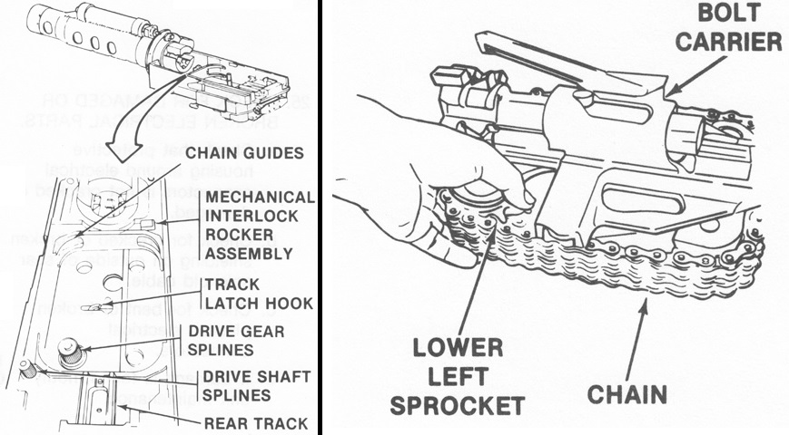
The disassembled receiver of the 25mm gun is shown on the left, and the bolt carrier and chain assembly that was inserted into the rectangular opening in the receiver is shown on the right. (Picture from TM 9-2350-252-10-2 C6.)
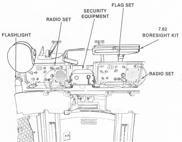
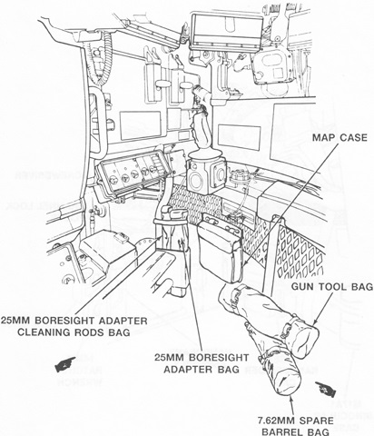
Stowage in the turret rear is illustrated in this sketch. The commander's helmet is hung on the left above the flashlight. (Picture from TM 9-2350-252-10-2 C6.)
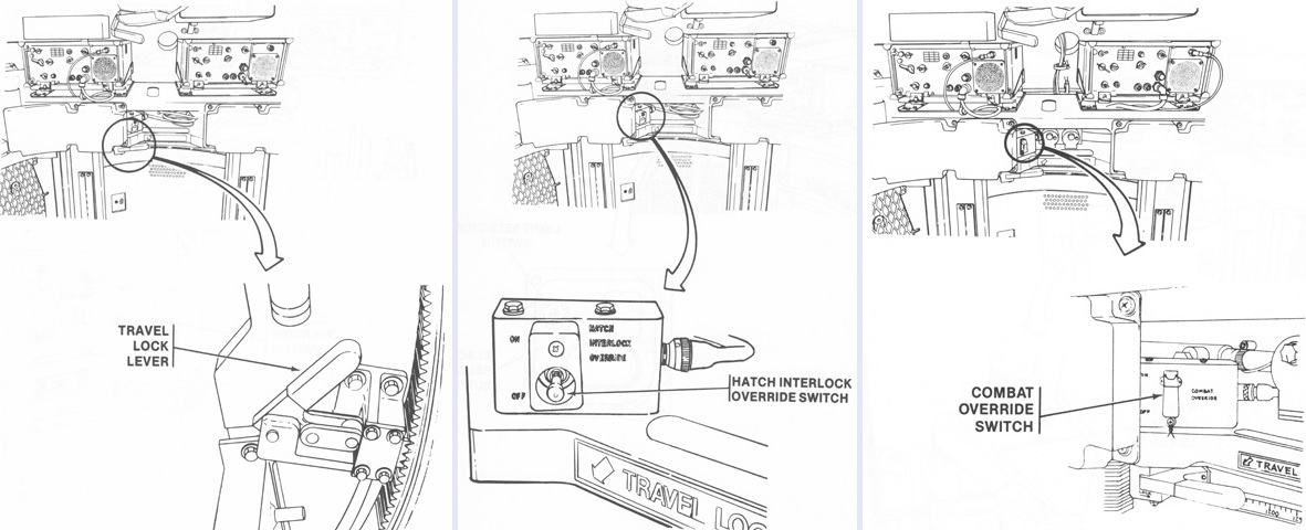
Also in the turret rear were the turret travel lock, hatch interlock override switch that would allow the turret operation in combat if the cargo or driver's hatch switches failed, and combat override switch that overrode all weapons fire control inhibitors except the 25mm gun below -1° between 2525 and 3825 mils and TOW below -14° between 3350 and 4175 mils. (Picture from TM 9-2350-252-10-2 C6.)
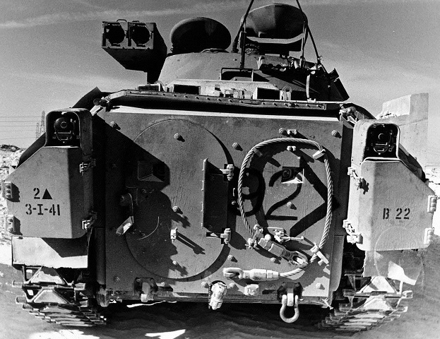
The ramp of the Bradley was flanked on each side by a rear stowage box, above which were mounted the vehicle's taillights. A towing pintle is centrally located under the ramp, and towing shackles are mounted on each side of this. A towing cable is stowed on the ramp, and in the center of the loop made by the cable is a firing port. Another firing port is in the left taillight's shadow in the oval ramp access door. The periscopes in the rear roof were not distributed evenly: two periscopes were on the vehicle's left side while a single periscope was provided on the right. (Picture taken 20 Nov 1990 by SPC Randall R. Anderson; available from the U.S. Army Center of Military History.)
The rear periscopes and the stop for the roof hatch are highlighted in this image.
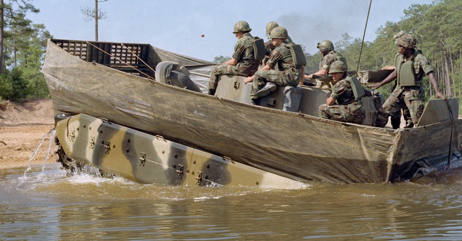
The water barrier is erected on this vehicle, and it has just completed crossing Victory Pond. (Picture taken 13 Jun 1983 by SPC5 Bobby Mathis; available from the Defense Visual Information Center.)
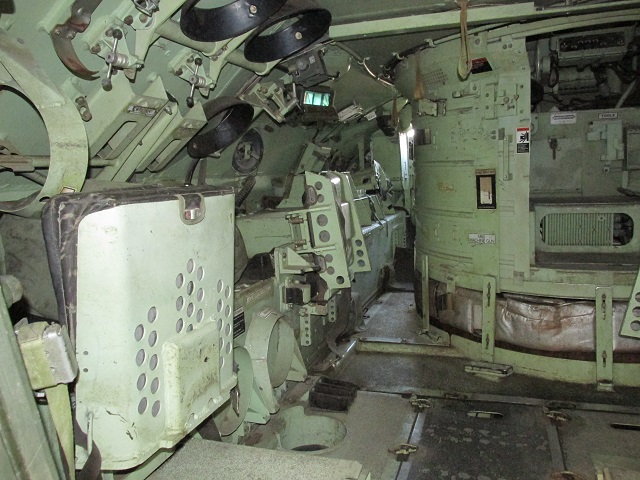
The left side of the passenger compartment is shown here. The tunnel to the driver's position is visible to the left of the turret basket, and seats for two dismounts are folded up on the left. A third man would sit between the driver and the turret basket. A periscope can be seen to the upper left, and a firing port is below it. The black discs near the ceiling and green discs near the holes in the floor as well as on the hull wall secured TOW missile reloads. Rations were stowed in the rectangular racks above the nearest seat.
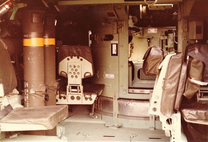
Some of the passenger seats are folded down in this machine, and TOW reloads can be seen to the left. (Photo by Richard S. Eshleman.)
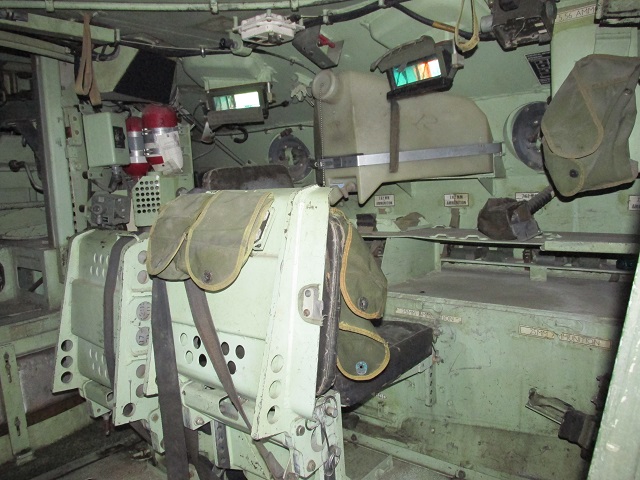
This picture is of opposite side of the passenger compartment. More individual seating for the dismounts can be seen, as well as the two firing ports and periscopes. Red fire extinguisher bottles are in the front right corner, and a plastic water tank is mounted on the hull wall. The red handle for activating the fire extinguishers is shrouded above the water tank. Ammunition for 7.62mm machine guns was stowed on the shelf under the water tank, and 25mm ammunition was stowed in the chest to the bottom right.
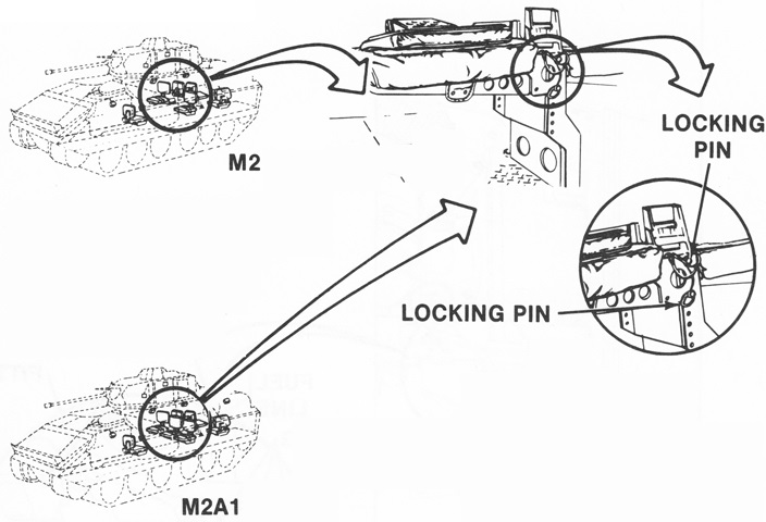
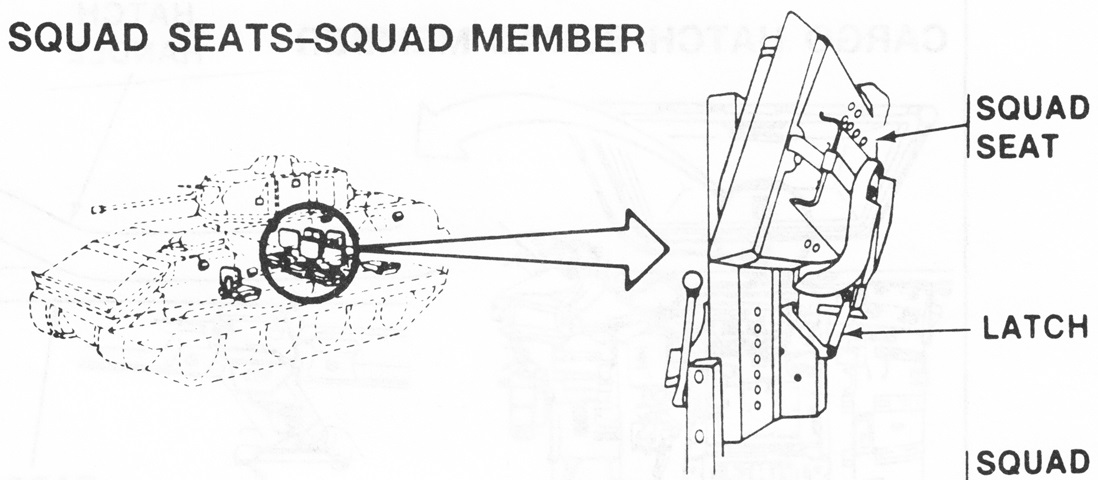
The squad seats in the M2 and M2A1 were secured by locking pins. (Picture from TM 9-2350-252-10-1 C1.)
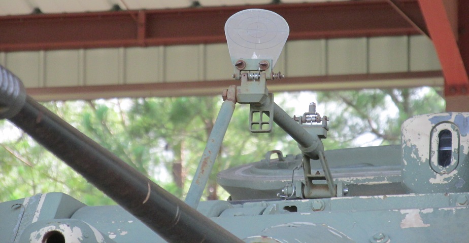
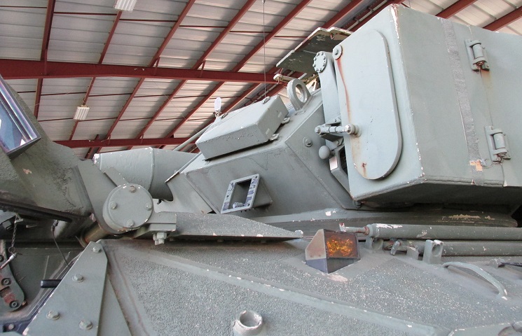
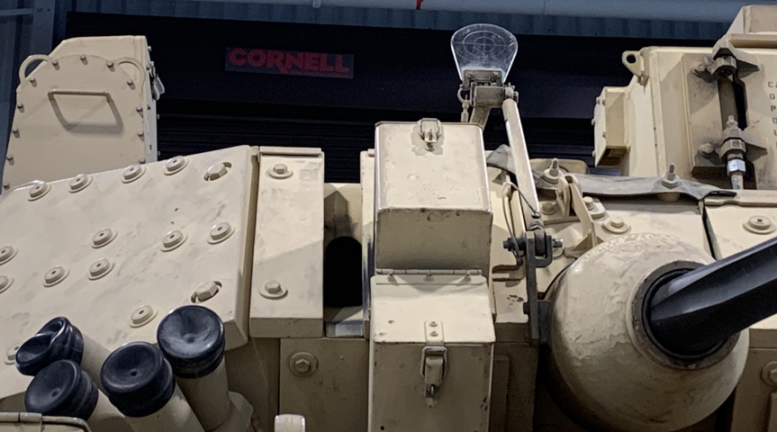
The commander's ring sight is detailed here, connected to the gun mantlet armor via an articulated arm. This allowed the commander to quickly aim at targets such as low-flying aircraft by lining them up with the plastic crosshairs and an aperture sight, which is missing on this vehicle. The mount for the aperture sight can be seen at the end of the horizontal arm near the commander's position.
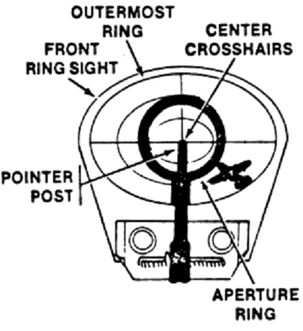
Lining a target up with the ring sight is diagrammed here. (Picture from TM 9-2350-252-10-2.)
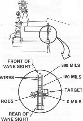
The commander was also provided with a vane sight which helped determine azimuth and elevation of a target. The rods of the rear sight were aligned with the wires of the front sight and the target. If the rods aligned with the bottom wires and the center of the target, it was at 0 mils elevation. Alignment with the middle wires indicated 180 mils of elevation, and the top wires indicated 360 mils of elevation. (Picture from TM 9-2350-252-10-2 C6.)
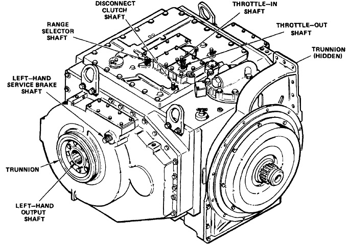
The left rear of the HMPT-500 transmission is sketched here. Its dry weight was 1860lb (844kg), it was 31.17" (79.17cm) long, 40.0" (102cm) wide, and 28.5" (72.4cm) tall. (Picture from TM 9-2520-270-34.)
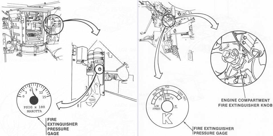
The crew compartment (left) and engine compartment (right) fire extinguishers can be seen. The crew compartment was protected by two fixed 5lb (2.3kg) Halon extinguishers and two portable 2.75lb (1.25kg) Halon extinguishers. The engine compartment was serviced by a single 7lb (3.2kg) Halon extinguisher. The fire suppression system was manually activated for the engine compartment via a knob at the driver's position or a handle on the hull exterior to the left of the driver. The crew compartment fire suppression system could be activated either automatically or manually via handles on the right side of the hull exterior and on the right side of the passenger compartment near the roof. (Picture from TM 9-2350-252-10-1 C1.)
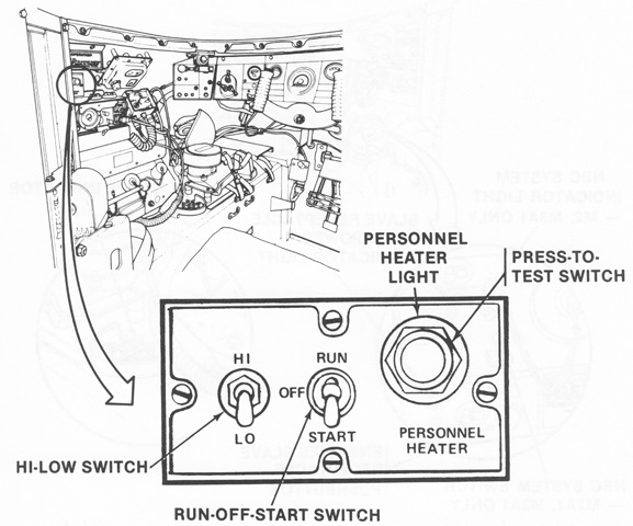
The diesel-fueled personnel heater was controlled by a box situated to the driver's left. (Picture from TM 9-2350-252-10-1 C1.)
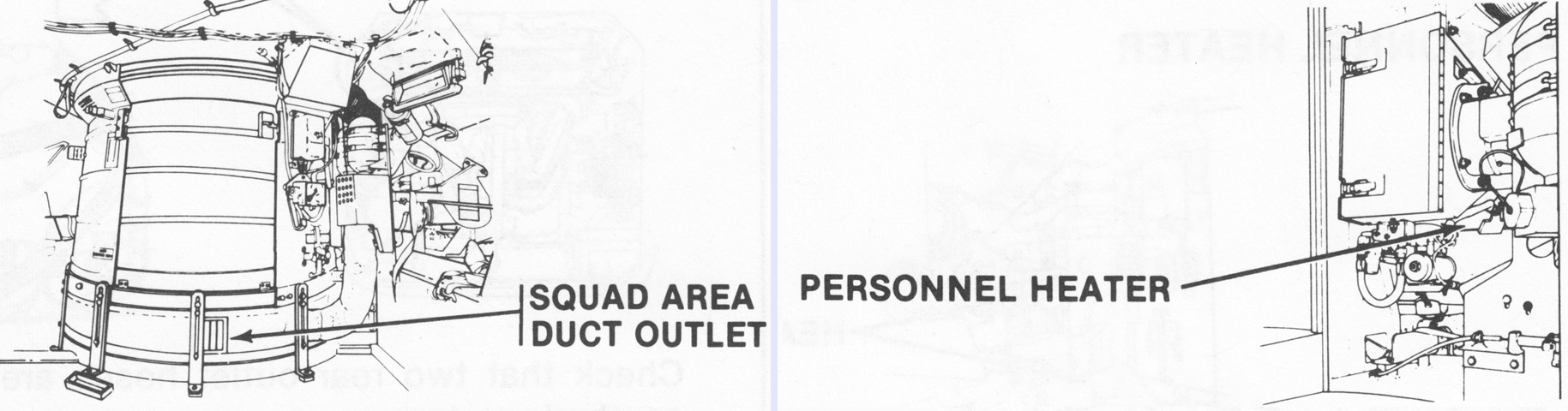
The ducting for the heater ringed the base of the turret basket. In the right-hand image, the heater can be seen in its location to the right of the turret basket. (Picture from TM 9-2350-252-10-1 C1.)
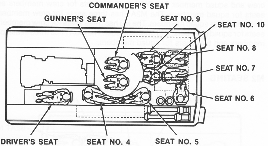
The seventh dismount can be seen in this diagram of the crew positions. (Picture from TM 9-2350-252-10-1 C1.)
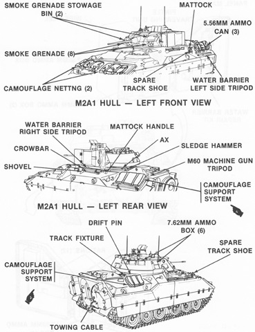
Revised external stowage is detailed in these sketches. (Picture from TM 9-2350-252-10-1 C1.)
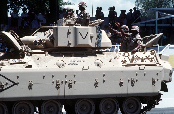
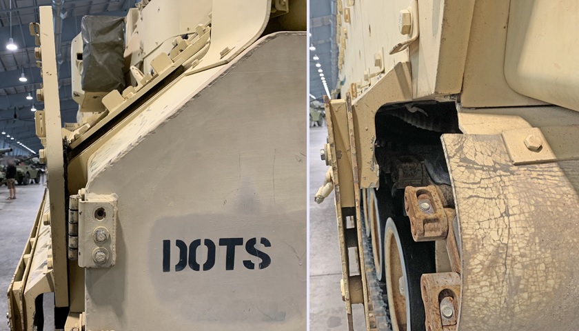
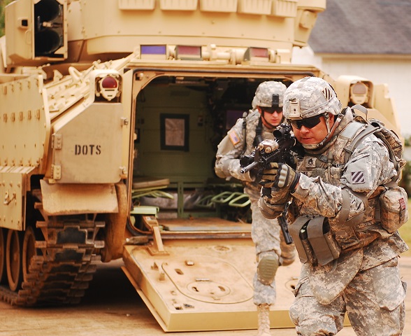
The side firing ports are clearly visible on this vehicle. The rear cargo hatch is open, allowing the soldiers to wave to the crowd watching the parade. The guard for the external fire extinguisher handle for the engine compartment is located below the panel labeled with the driver's name. This vehicle lacks the boxes for smoke grenade stowage on the turret front visible on the vehicle above. The turret interlocks were modified for the M2A1 Bradley, and the changes were: if the driver's hatch was opened beyond the pop-up position, no weapons would fire over an arc of between 4972 to 25 mils traverse. If the cargo hatch was in the vertical or full-open positions, the TOW launcher would not fire, and the guns would not fire over an arc of between 2125 to 4375 mils traverse. Modifications to the deck clearance controls included the automatic elevation of the gun rotor to +17° when traversed between 2275 and 4225 mils if the cargo hatch was in the vertical or full open positions; elevation of the gun rotor to +17° between 5125 and 0350 mils if the driver's hatch was open beyond the pop-up position; and elevation of the TOW launcher to -14° when traversed between 2275 and 4225 mils. (Picture taken 8 Jun 1991 by LCPL Contreras; available from the Defense Visual Information Center.)
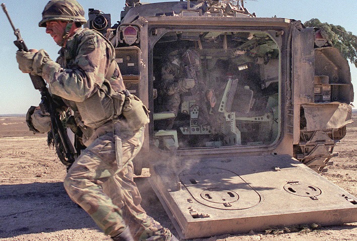
The rear ramp is lowered on this vehicle, allowing the dismounts to exit and permitting a glimpse into the troop compartment. There were seven troops in the passenger compartment, and each had their own seat. One sat facing inboard in the vehicle's left rear corner, two pairs of soldiers sat back-to-back in the vehicle's right rear corner, and two soldiers sat back-to-back to the left of the turret. The stowage boxes on either side of this vehicle's rear ramp are missing their covers, and appear damaged. The periscopes behind the rear cargo hatch can also be seen. (Picture taken 27 Jan 1986 by William U. Rosemund; available from the Defense Visual Information Center.)
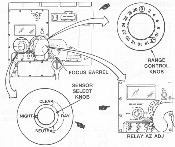
The ISU is detailed in this picture. The range control knob set the range of the 25mm gun from 0 to 3000m. The sensor select knob filtered the light entering the ISU. NIGHT activated the night vision system; CLEAR was used during normal daylight conditions; while NEUTRAL filtered bright sunlight and protected the eyes against laser emissions. The RELAY AZ ADJ adjusted the electronic alignment reticle to the TOW reticle in azimuth. (Picture from TM 9-2350-252-10-2 C6.)
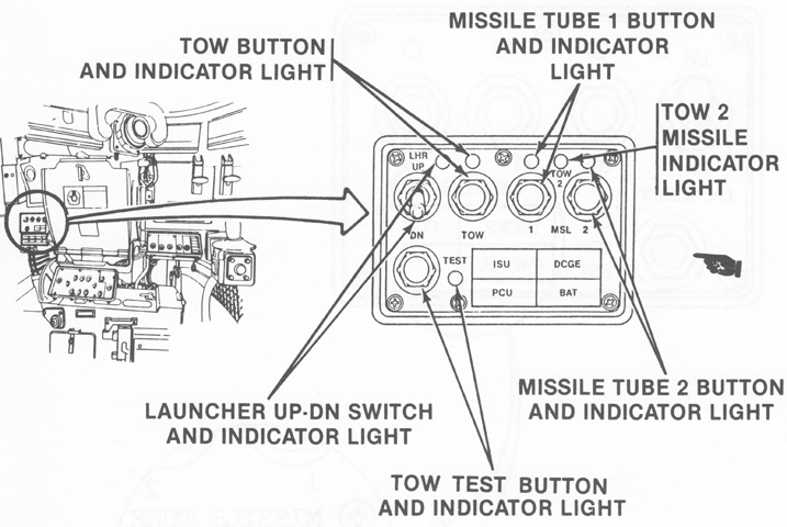
The TOW control box was slightly modified in the new vehicle. An indicator light was added for when TOW 2 missiles were loaded in the selected tube. The TOW 2 necessitated the use of night vision power in order to ensure proper tracking of the missile. The annunciator lights at the bottom right revealed failures in the ISU, the digital command guidance electronics (DCGE), power control unit (PCU), and batteries (BAT). (Picture from TM 9-2350-252-10-2 C6.)
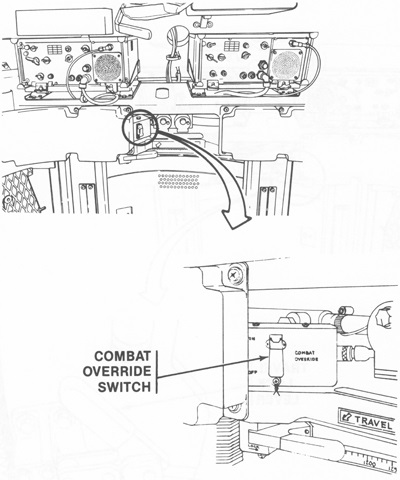
The combat override switch was similar to the earlier hatch interlock override switch in that it permitted turret operation in combat if the driver's or cargo hatch switches failed. It would automatically return to the off position when the turret power was turned off. (Picture from TM 9-2350-252-10-2 C6.)
The missile launcher on the M2A1 had single lock and loading handles in contrast to the pair of each found on earlier vehicles. (Picture from TM 9-2350-252-10-2 C6.)
Schematics of the basic TOW missile and the Improved TOW are shown in this image. (Picture from FM 23-1 Bradley Gunnery.)
This drawing shows the difference between TOW 2 and TOW 2A. (Picture from FM 23-1 Bradley Gunnery.)
The interior of the TOW 2B is sketched here. Note the two downward-firing warheads at the front of the missile. (Picture from FM 23-1 Bradley Gunnery.)
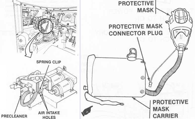
The driver's NBC equipment is shown on the left, and the M25A1 protective mask is on the right. The mask's connector plug was inserted into a receptacle found at the combat vehicle crewman helmet's microphone jack. The heater controls for the NBC system can be seen in the left image just above the "PRECLEANER" arrow. The heater was to be used during cold weather to prevent facial frostbite caused by cold filtered air. The system would not protect from carbon monoxide. (Picture from TM 9-2350-252-10-1 C1.)
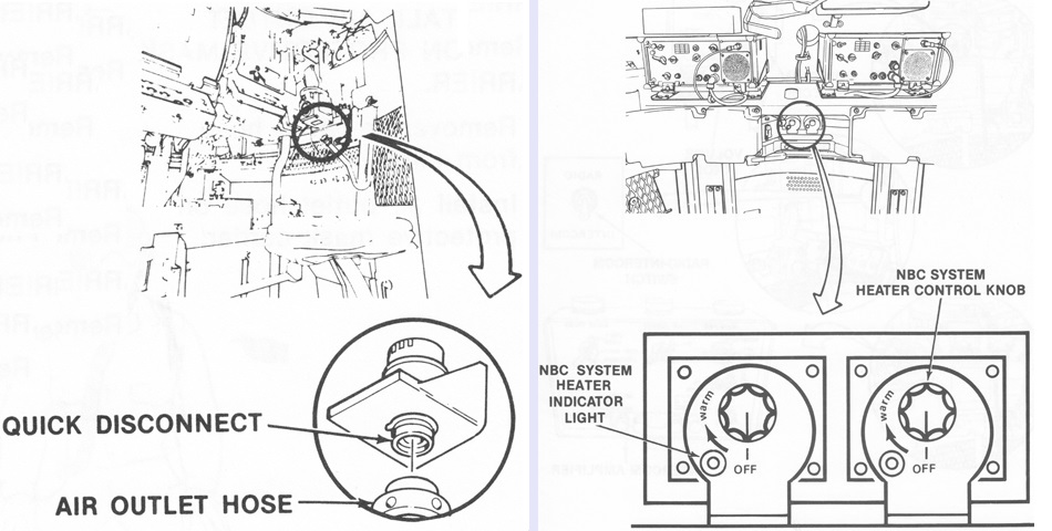
The turret crew were both provided with outlets for the NBC system to which they could attach their own M25A1 masks. Their individual NBC heater control knobs are shown on the right. (Picture from TM 9-2350-252-10-2 C6.)
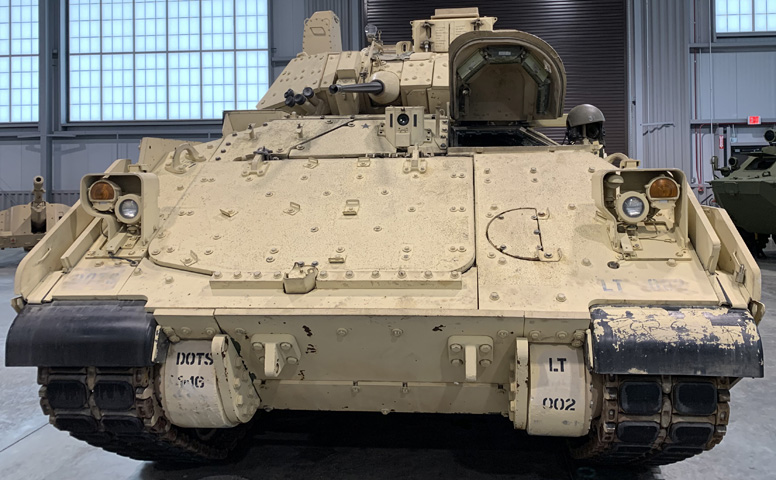
The enhanced side armor skirts and lack of a trim vane are immediately apparent when compared with earlier vehicles. (Picture from TM 9-2350-284-10-1 C1.)
The ramp firing ports were retained, but the side ports were blocked by the additional armor. (Picture from TM 9-2350-284-10-1 C1.)
External stowage is detailed in this image. (Picture from TM 9-2350-284-10-1 C1.)
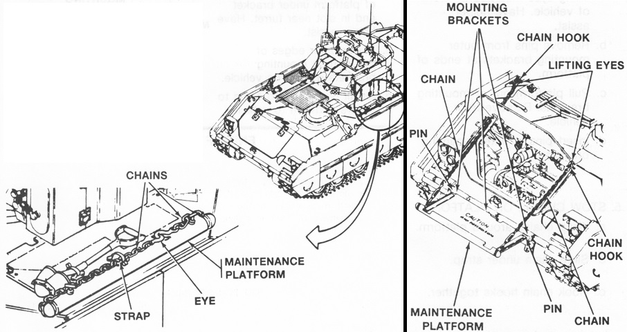
With the omission of the trim vane, a maintenance platform was stowed on the left side of the hull to enable work to be done on the engine and powertrain. (Picture from TM 9-2350-284-10-1 C1.)
The revised external lighting can be compared with that found on earlier vehicles. (Picture from TM 9-2350-284-10-1 C1.)
The M2A2 returned to the six-man dismount squad originally carried by the M2, but all were now seated in the rear compartment instead of placing one man behind the driver. (Picture from TM 9-2350-284-10-1 C1.)
All of the squad seats except seat number 5 changed to locking latches instead of locking pins. Seat 5 retained the locking pin system. (Picture from TM 9-2350-284-10-1 C1.)
The cover over the driver's periscopes can be seen in this illustration of his hatch controls. (Picture from TM 9-2350-284-10-1 C1.)
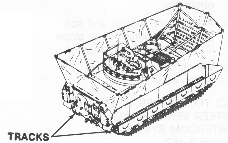
The water barrier is depicted erected; note that the tall side armor skirts were external to the barrier. (Picture from TM 9-2350-284-10-1 C1.)
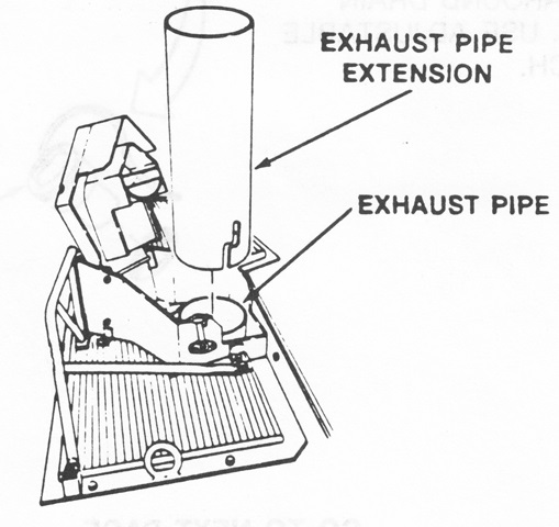
An extension to the exhaust pipe was added when swimming operations were undertaken. (Picture from TM 9-2350-284-10-1 C1.)
The fire control zones for the M2A2 are drawn above. If the driver's hatch was open beyond popped, TOW missiles would not fire and the 25mm and 7.62mm guns would not fire over the driver's hatch between 4975 and 25 mils. If the cargo hatch was in the TOW load position, no turret weapons would fire. If the cargo hatch was in the vertical or full-open positions, the TOW launcher would not fire, and the 25mm and machine guns would not fire over the rear deck between 2125 and 4375 mils. (Picture from TM 9-2350-284-10-2 C6.)
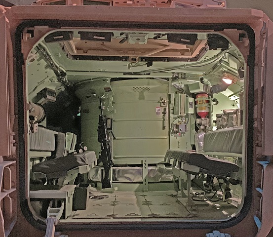
Peering into the passenger compartment of this restowed M2A2 Bradley, the improved dismount seating arrangement is immediately apparent versus earlier vehicles. Six of the infantry squad sat on inward-facing benches, with the seventh man in the tunnel to the driver's compartment. A TOW missile reload can be seen above the left-hand backrest, and the periscopes in the rear hull roof can be seen above and below the armor.
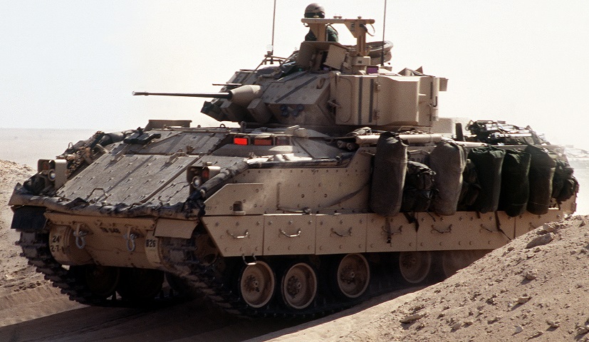
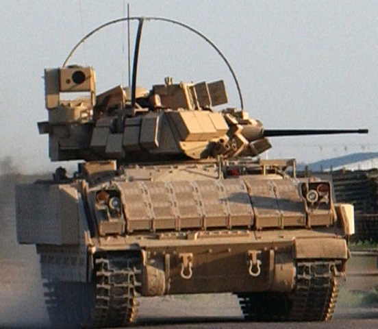
The applique and spaced armor is apparent on the front and sides of this M2A2ODS, and the attachment points for the applique armor tiles pockmark the surface of the vehicle. The trim vane on the hull front slope has been deleted, and the engine access hatch is now visible. The 7.62mm coaxial machine gun lacks the barrel shroud like the M2 example above. Smoke grenade stowage was again moved, to the boxes visible on each side of the 25mm gun on the underside of the turret front. The platform above the gunner's sight housing was for a missile countermeasure device that ended up not being fielded. Note also the new headlight clusters compared to earlier vehicles. With the armor upgrades, the vehicle has lost its trim vane, but it retained its water barrier, rolled up around the perimeter of the hull. (Picture Picture taken by PFC Tracey Hall-Leahy; available from the National Archives.)
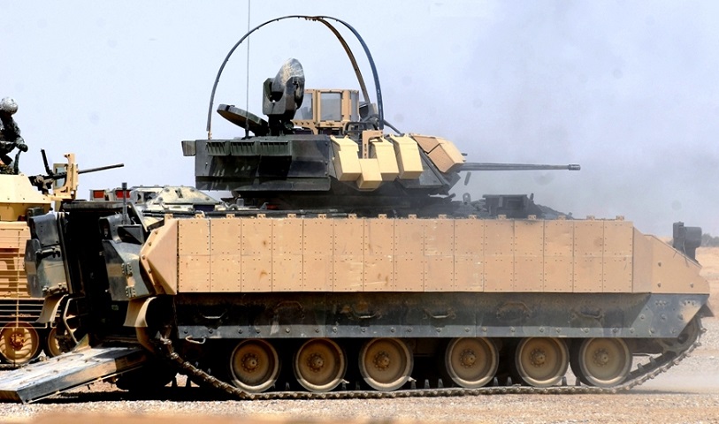
This vehicle, firing its 25mm gun, is fitted with enhancements like ERA tiles, a shield for the commander, and the dome tent over the turret roof that was intended to prevent strikes with overhead power lines. Empty shell casings can be seen bouncing below the gun barrel. (Picture taken 13 Sep 2008 by PFC Michael Schuch; available from the Defense Video & Imagery Distribution System.)
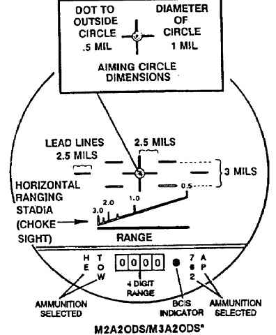
The gunner was provided with a laser rangefinder in the M2A2ODS which provided a 4-digit range readout from 200m to 9990m in 5-meter increments and automatically applied superelevation. Again, the air defense reticle is not represented in this image. (Picture from FM 23-1 Bradley Gunnery.)
ERA tiles and the dome tent are present on this machine, and a view of the front of the CIV can be had. Note that the headlight clusters have been moved to atop the added armor. (Picture taken 19 Jun 2006 by SPC Cal Turner; available from the Defense Video & Imagery Distribution System.)
This vehicle has been fitted with new double-pin tracks with replaceable rubber pads. The driver's thermal camera is visible on the front hull to his front right. (Photo by Richard S. Eshleman.)
The CIV is in its stowed position on this vehicle, and the driver's hatch is open.
A closer look is given at the driver's thermal camera. Note the heavily fluted barrel on the 25mm gun.
The aperture ring for the commander's ring sight is visible behind the front ring sight. The opening for the coaxial machine gun is outboard of the smoke grenade stowage boxes, although the gun is not present. Just above the 25mm gun and adjacent to the arm for the commander's ring sight, an arm is visible attached to a flap that sealed the chute from which empty 25mm ammunition cases were ejected.
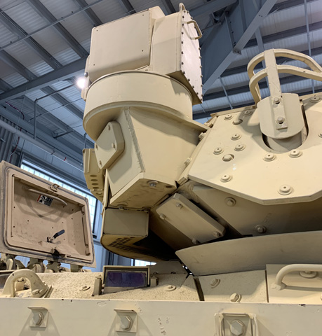
The commander's independent viewer was aimed down when not in use. An antenna guard is on the turret side ahead of the CIV, and the troop compartment hatch is open. The hatch lacks periscopes, since these remained mounted in the hull.
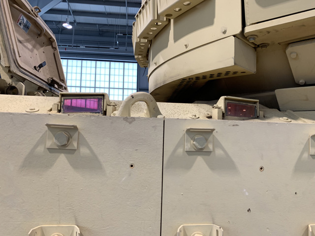
Although the firing ports were covered by the additional armor, the periscopes in the passenger compartment sides were retained.
The applique side armor and spaced armor skirt can be compared on the left and right, respectively. A stowage box is on the right in the left-side image, and the taillight guard is bolted to the top of the stowage box.
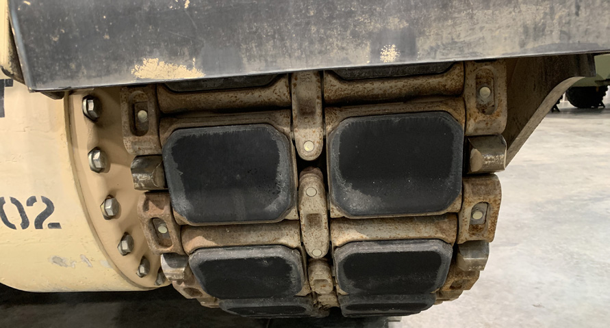
Details of the new double-pin track can be seen in this picture. The drive sprocket teeth are visible engaging the end connectors, and the final drive housing bolts are unpainted.
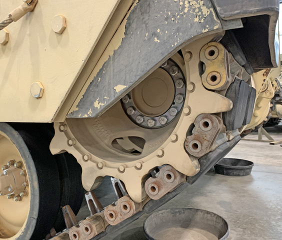
The drive sprocket for the new tracks is highlighted here.
Compared to the M2A1 above, the entryway of the M2A3 is free of folding seats, making mounting and dismounting the vehicle easier for the infantry. The squad was provided with a folding bench attached to each wall of the passenger compartment, and these can be seen through the open ramp. The seventh man was positioned facing to the rear in the tunnel behind the driver. Here, squad leader SSG Benjamin Jones (foreground) and his men are undergoing military operations in urban terrain training. (Picture Picture taken 23 Sep 2011 by SPC Erik Anderson; available from DefenseImagery.mil.)
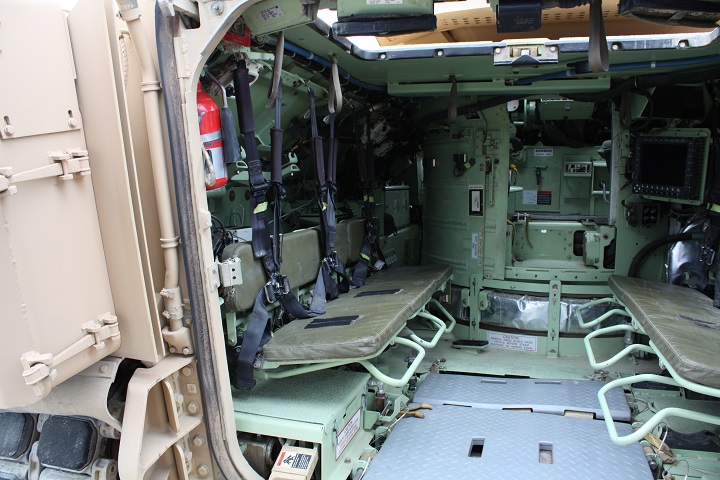
A view into the passenger compartment is provided here. The roof hatch is open, and periscopes can be seen in the roof just inside the door. Energy-absorbing benches and footrests have been installed, along with restraints for the squad. The flat-screen display for the squad leader can be seen in the front right of the compartment. (Photo by Richard S. Eshleman.)
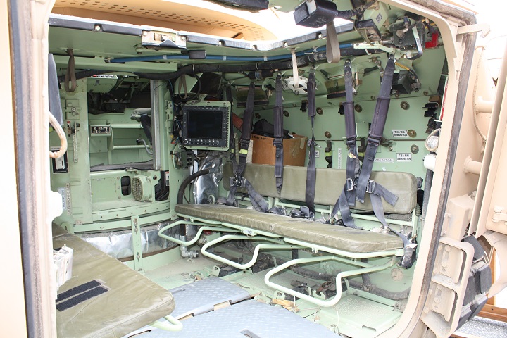
Another view into the passenger compartment shows more detail of the rear armor arrangement, turret basket opening, and squad leader's display. (Photo by Richard S. Eshleman.)
