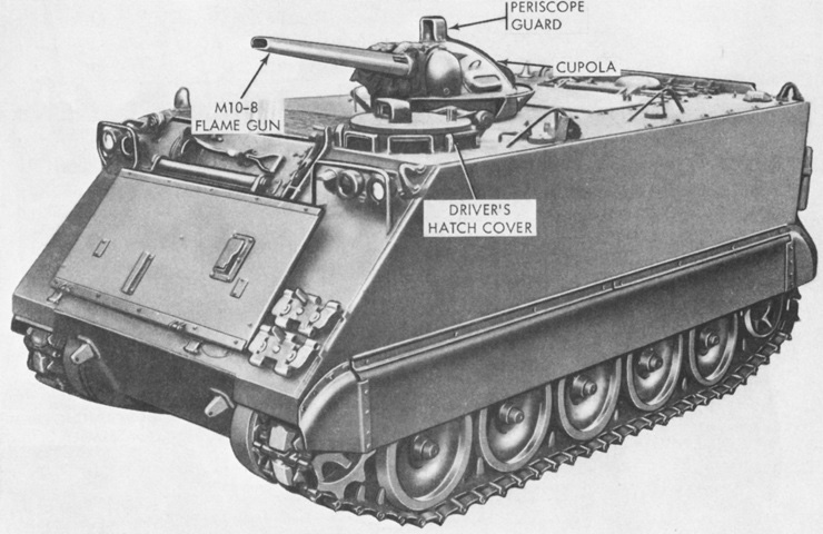
Self-propelled Flame Thrower Carrier M132.
The usual machine gun cupola on this vehicle has been replaced by the M8 flame gun cupola group. The coaxial machine gun is hidden by the flame gun barrel. (Picture from TM 9-2300-224-10.)
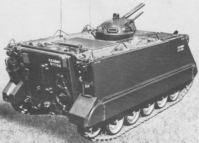
The machine gun is visible from this angle. (Picture from TM 3-1040-209-35P.)
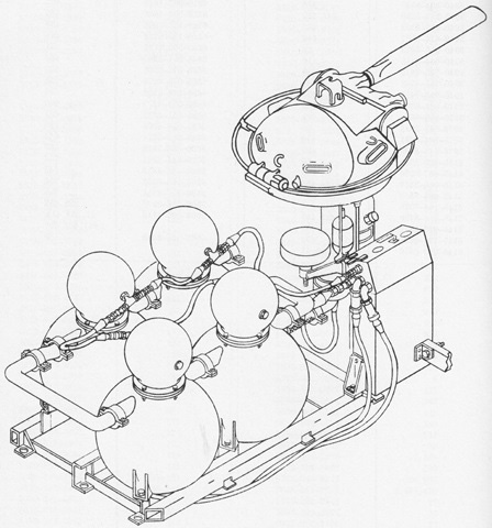
A schematic of the M10-8 main armament flame thrower is sketched here. The larger flame fuel tanks pressurized at 325psi (22.8kg/cm²) supported smaller compressed air tanks at 3,000psi (210kg/cm²). Both the fuel tanks and air tanks were connected in series and finally to the cupola group's rotating joint. The air tanks fed air to the fuel tanks via the pneumatic control unit. In addition to the standard fixed fire extinguisher, two more 10lb (4.5kg) fixed extinguishers were housed in a cabinet on the floor to the right of the flame gun operator. Both of these extinguishers were actuated by a single control handle. (Picture from TM 3-1040-209-35P.)
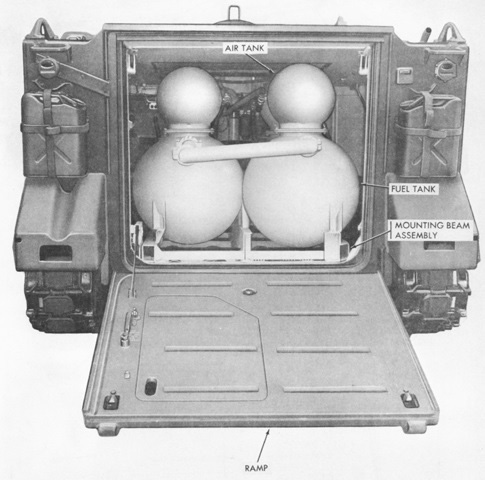
The size of the fuel and air tanks can be appreciated with this interior view. (Picture from TM 9-2300-224-10.)

A partially exploded view of the flame gun assembly is presented here. (Picture from TM 3-1040-209-35P.)
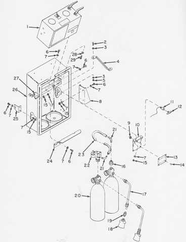
Parts of the pressure control and CO2 fire extinguisher cabinet assembly next to the flame gun operator are shown in this drawing. The two fire extinguishers were operated by the single handle labeled number 12. (Picture from TM 3-1040-209-35P.)
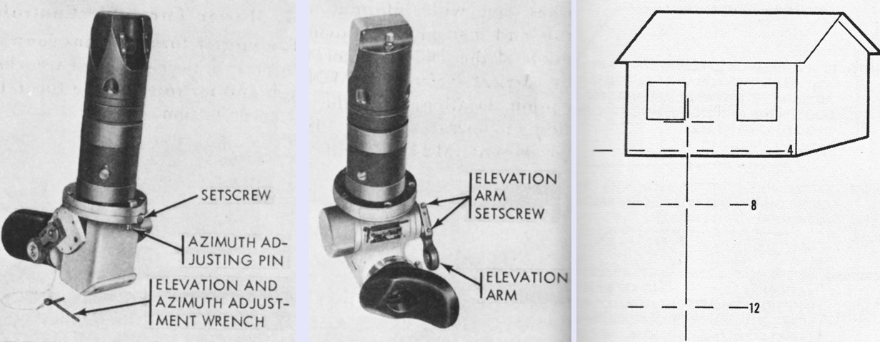
The controls for the gunner's periscope M28D are labeled in the left two images. The reticle pattern is sketched at the right using the bottom corner of a window as a boresighting reference. (Picture from TM 9-2300-224-10.)
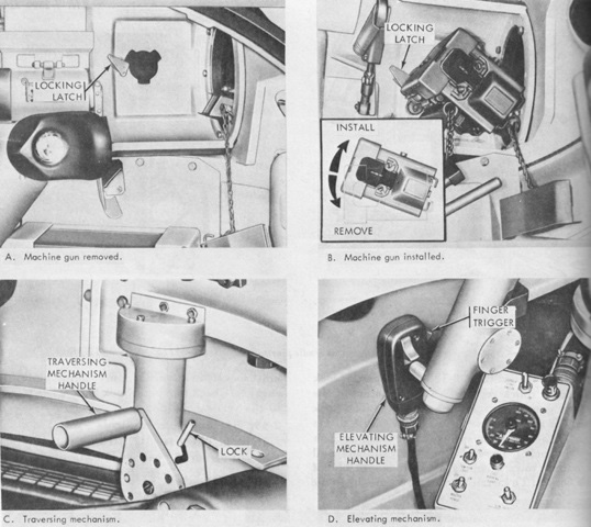
The cupola controls for the machine gun are detailed in these panels. (Picture from TM 9-2300-224-10.)
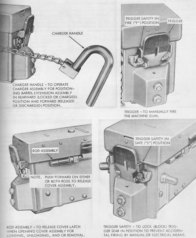
The controls on the machine gun itself are shown here. (Picture from TM 9-2300-224-10.)
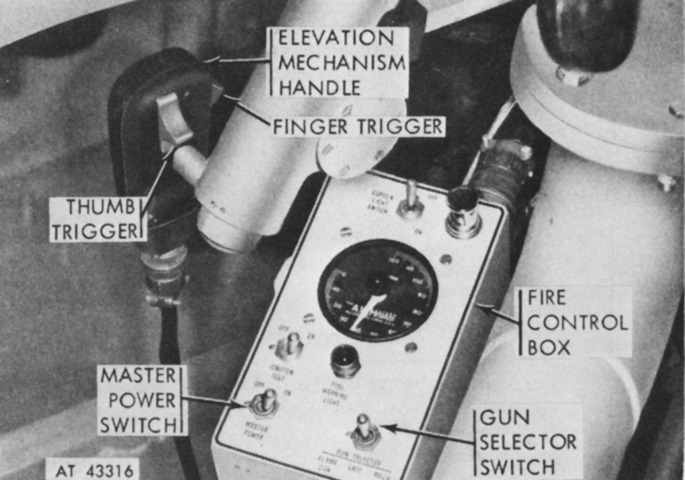
The fire control box allowed the gunner to choose between electrically arming the machine gun or the flame gun, and also enabled the gunner to put the electrical control system in a safe condition. (Picture from TM 9-2300-224-10.)
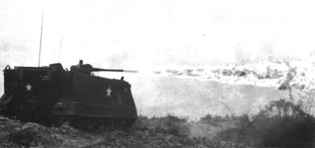
In Vietnam, the M132 was also used to destroy foliage and antipersonnel mines, as illustrated here. (Picture from Mechanized and Armor Combat Operations in Vietnam.)
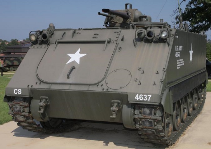
The position for the smaller coaxial machine gun is visible to the flame gun's right. The guard for the M28D sighting periscope can be seen on the cupola's crown. The trim vane is also absent, granting us a view of the powerplant compartment front door. (Picture courtesy 8Hussar Ottawa.)
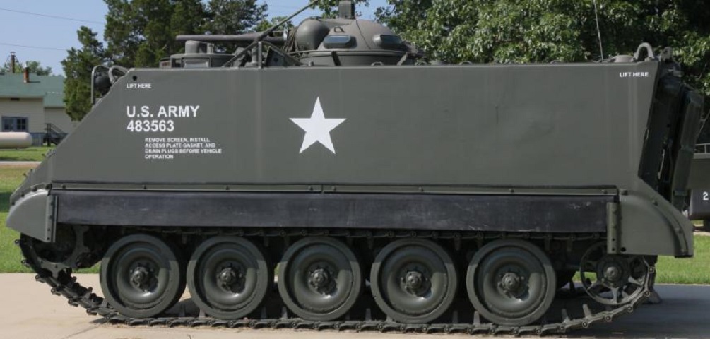
The base of the cupola was ringed with four vision blocks, two of which can be seen here. (Picture courtesy 8Hussar Ottawa.)
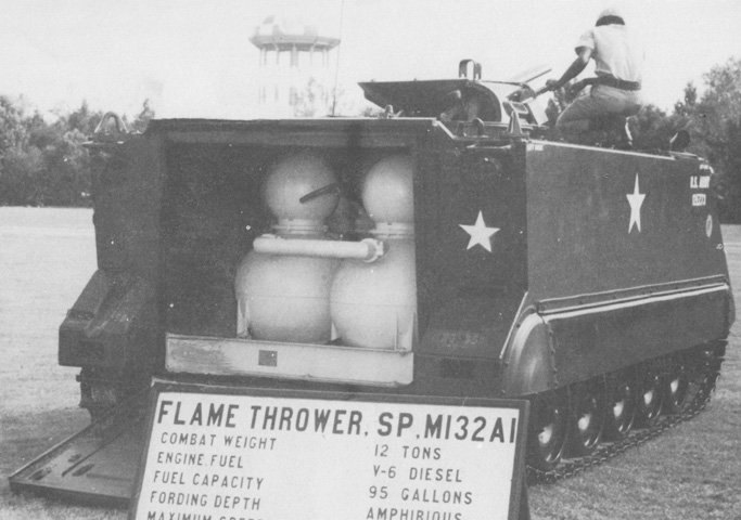
The voluminous tanks and plumbing are visible through the open rear ramp, and the cupola door is also open. The sighting periscope is not present. (Picture from Tactical Vehicles.)
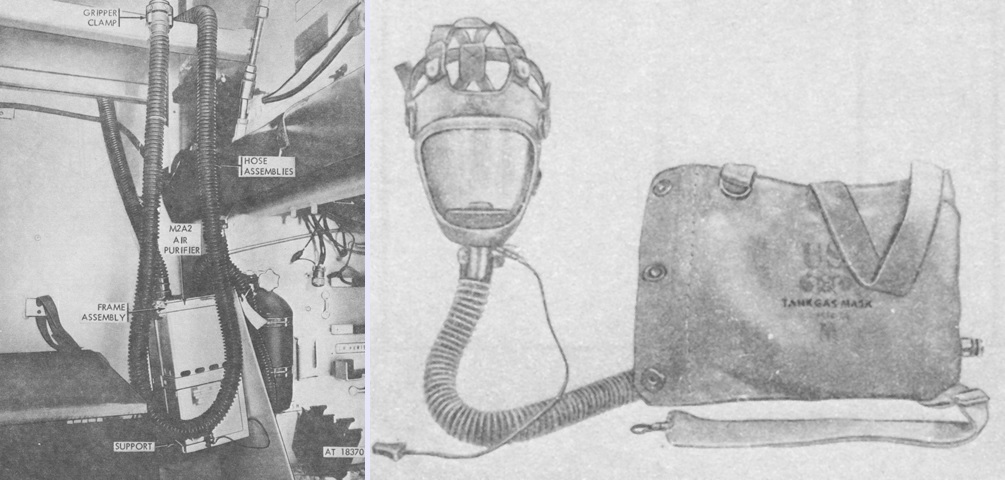
The M8A3 gas-particulate filter unit is shown installed on the left, and an M14A1 tank gas mask is displayed on the right. The air purifier M2A2 weighed 20 ¼lb (9.185kg), and was 13 x 7 ½ x 6" (33 x 44.5 x 15cm). (Picture from TM 9-2300-257-10.)
