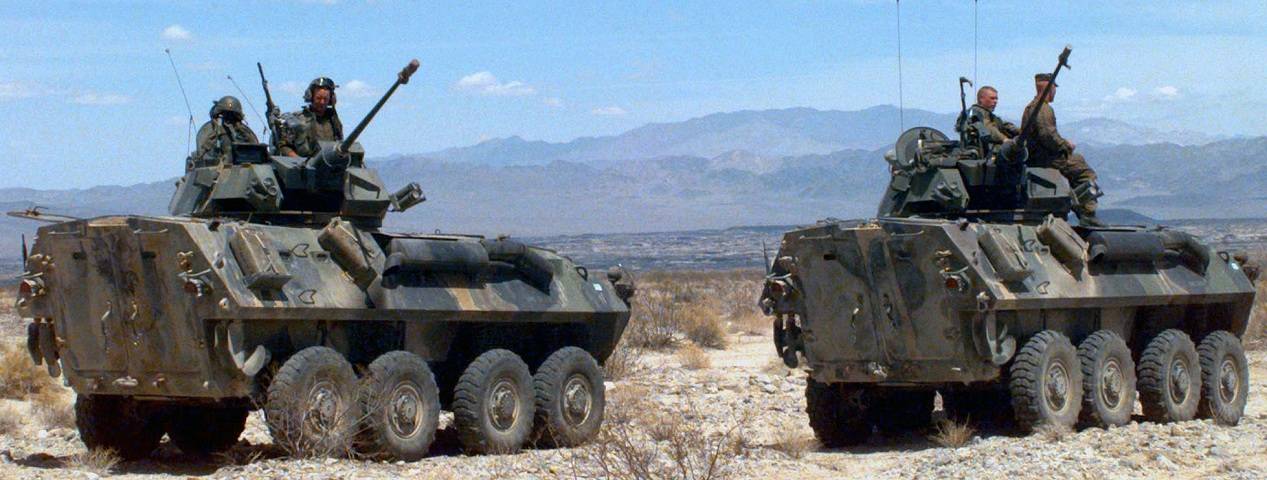
LAV-25 at the Marine Corps Air Ground Combat Center.
These two LAV-25s have their turrets trained to their rears. The turret machine guns on the commander's hatches are visible on both vehicles, as are the large double rear doors to their passenger compartments. Each of the rear doors has a vision block installed, and there are also vision blocks in the passenger compartment between the water cans. The left-hand rear roof hatch is open on the left vehicle. The engine exhaust with the large muffler is routed along the right side of the hull, and the propellers and rudders for water operation can be seen above and behind the rear wheels. Two four-round smoke grenade launchers are mounted on each vehicle's turret. These vehicles were with Alpha Company, 2nd Light Armored Reconnaissance Battalion during Combined Arms Exercise 5-97. (Picture taken 19 Apr 1997; available from the National Archives.)
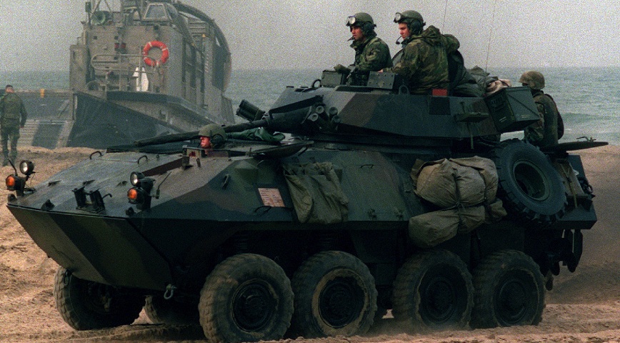
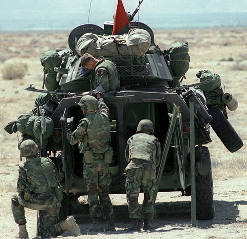
A marine is sitting on the open rear roof hatch on this vehicle. The emergency hatch is visible on the upper hull side between the front and rear axle sets. The driver and turret crew were provided with ATGM wire cutters to prevent injury from wires strewn across the battlefield. They are both folded down on this vehicle, on the front hull in front of the driver's hatch and on the turret front above the 25mm gun. The head assembly for the thermal sight is on the turret's left side, in front of the gunner's position. Periscope gun sights are in front of the commander on the turret's right side. The self-recovery winch fair lead can be seen on the prow of the hull; the winch itself was located under a hatch just behind the fair lead. A large trim vane for water operations was stowed on the lower part of the front hull. This vehicle was part of Delta Company, 1st Light Armored Reconnaissance Battalion, and was taking part in Exercise Kernel Blitz '99. (Picture taken 24 Apr 1999; available from the National Archives.)
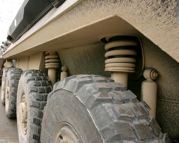
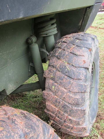
Details of the suspension are shown in this image. Each wheel was provided with a shock absorber, and the springs on the front wheels are visible from the outside. One of the rear propellers can be seen as well, and the large engine muffler resides on the right side of the vehicle. This vehicle is waiting in line at a wash station before coming back to Okinawa from the Amphibious Ready Group Exercises 2004. (Picture taken 21 Mar 2004; available from the National Archives.)
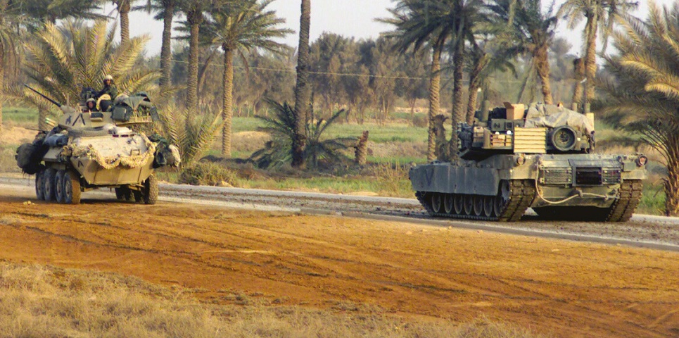
This image provides a size comparison between the LAV-25 and an M1A1 tank from Charlie Company, 1st Tank Battalion, during Operation Iraqi Freedom. (Picture taken 31 Mar 2003 by SGT Paul L. Anstine, II; available from the National Archives.)
The open rear doors and roof hatches can be seen on this vehicle, from which minefield guide stakes are being unloaded. The thickness of the rear doors and roof can be noted. (Picture taken 5 Aug 1997 by Pvt Jay M. Dostal; available from the National Archives.)
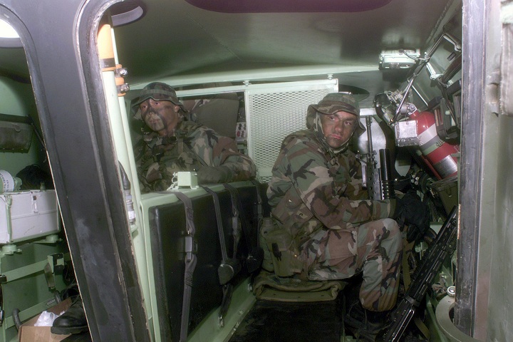
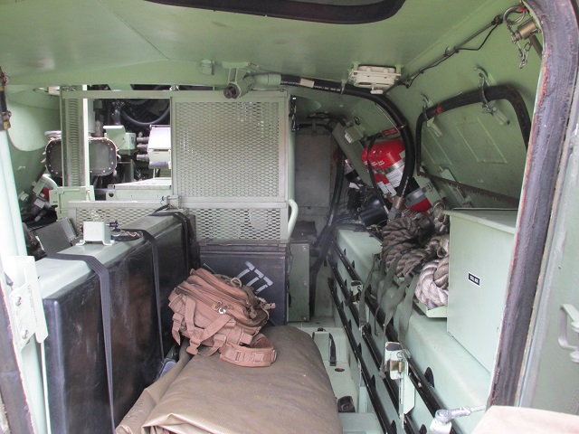
The interior of the passenger compartment is illustrated in this image. Six troops could be accommodated sitting back-to-back on the two bench seats. Red fixed fire extinguishers can be seen towards the front on the right, and the vertical fuel filler pipe is partially hidden by the center armor between the open doors. The roof hatches can just be seen, and daylight is coming through the open left-hand hatch. This vehicle was part of Charlie Company, 3rd Light Armored Reconnaissance Battalion, and was taking part in Exercise Kernel Blitz 2001. The marines pictured are HM Dan Ocampo on the left and LCPL Burns on the right. Behind them, CPL Michael Probst sits in the vehicle's gunner's seat. (Picture taken 26 Mar 2001 by LCPL Brent T. Harvey; available from the National Archives.)
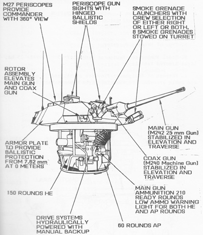
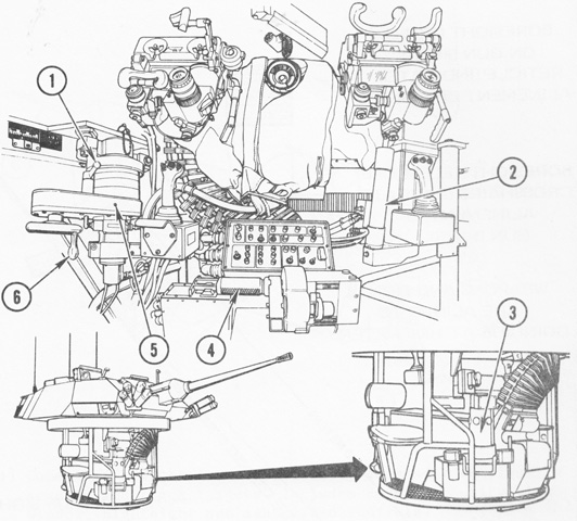
Features of the turret are outlined in this sketch. This is an early vehicle constructed before the gunner's thermal sight was added. (Picture from TM 08594A-10/1 Operator's Manual Light Armored Vehicle LAV-25 (2320-01-123-1602) Turret PN 7566200-021.)
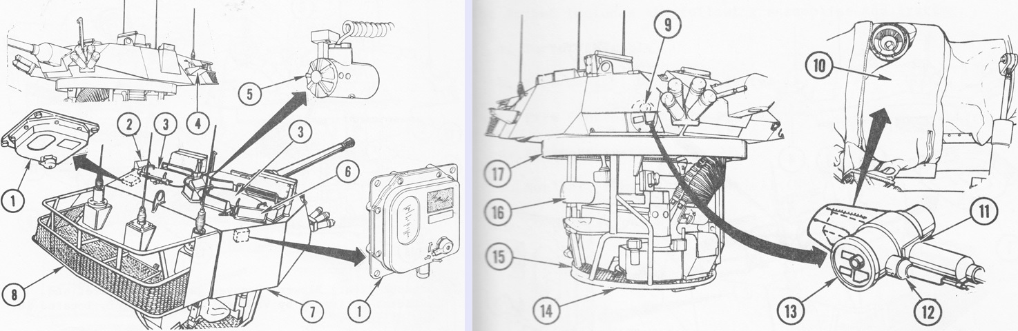
More turret details are drawn above. 1. Domelights. 2. Gunner's M27 periscope. 3. Turret hatches. 4. Grenade stowage shelf. 5. Detachable utility light (inside turret above and between gunner and commander). 6. Commander's M27 periscopes (7). 7. Armor shell. 8. Bustle rack. 9. Exhaust (vent) blower. 10. Weapon enclosure bag. 11. Main gun mount. 12. Coax gun mount. 13. Rotor assembly. 14. Slip ring. 15. Basket assembly. 16. Seats (2). 17. Turret support bearing. (Picture from TM 08594A-10/1 Operator's Manual Light Armored Vehicle LAV-25 (2320-01-123-1602) Turret PN 7566200-021.)
The turret interior is drawn. 1. Turret manual or power drive select lever. 2. Elevation drive. 3. Hydraulic power supply. 4. Manual elevation handcrank. 5. Traverse drive. 6. Manual traverse handwheel. (Picture from TM 08594A-10/1 Operator's Manual Light Armored Vehicle LAV-25 (2320-01-123-1602) Turret PN 7566200-021.)
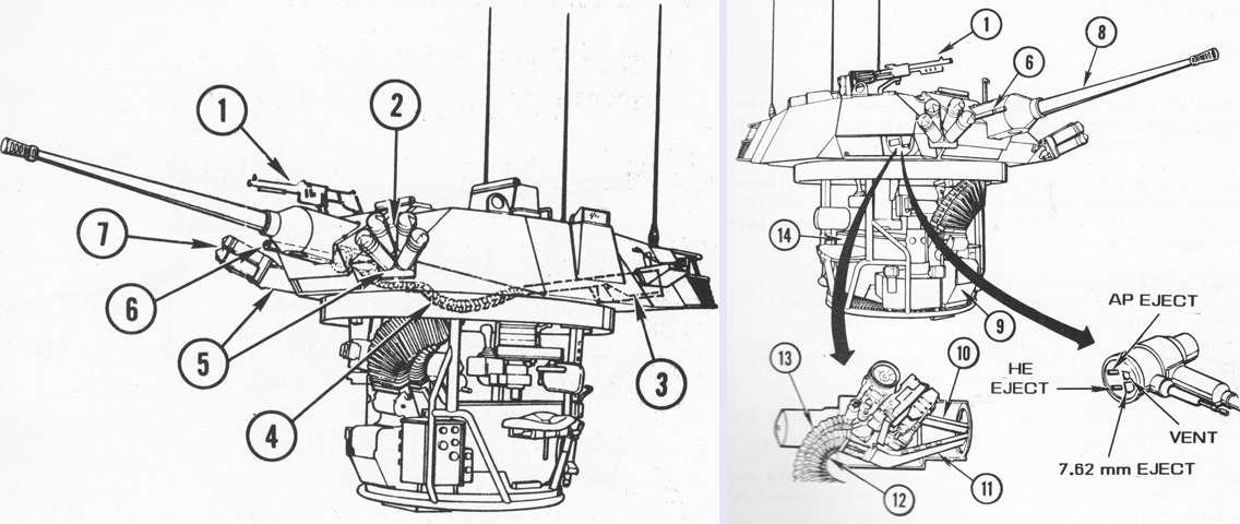
The armament is detailed here. 1. Pintle mounted 7.62mm M60 machine gun. 2. Left L8A1 smoke grenade launcher. 3. Coax gun ammo ready box and feed chute. 4. Coax gun feed chute. 5. Grenade launcher mounts. 6. Coax 7.62mm M240 machine gun. 7. Right L8A1 smoke grenade launcher. 8. 25mm M242 automatic cannon. 9. Main gun AP ammo ready box and feed chute. 10. AP link ejection chute. 11. HE link ejection chute. 12. HE feed chute. 13. AP Feed chute. 14. Main gun HE ammo ready box and feed chute. (Picture from TM 08594A-10/1 Operator's Manual Light Armored Vehicle LAV-25 (2320-01-123-1602) Turret PN 7566200-021.)
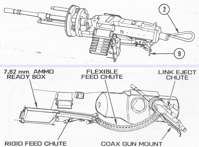
The coaxial machine gun is drawn at the top installed in its mount with the charger cable (2) and manual fire lever (9) highlighted, while at the bottom the machine gun mount is depicted in the turret with the ammunition chute attached. (Picture from TM 08594A-10/1 Operator's Manual Light Armored Vehicle LAV-25 (2320-01-123-1602) Turret PN 7566200-021.)
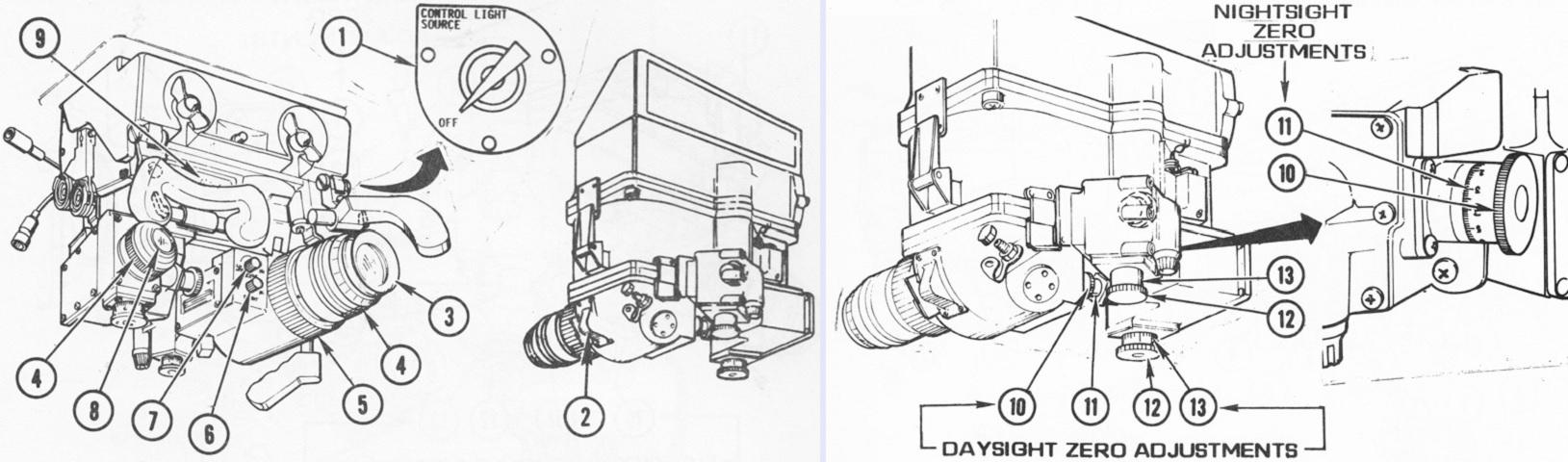
The M36/LAV sight is seen from the rear and front. 1. Daylight reticle brightness control (not part of M36/LAV assembly). 2. Nightsight power switch. 3. Nightsight eyepiece. 4. Diopter rings. 5. Nightsight focusing ring. 6. Nightsight light amplification tube adjustment control. 7. Nightsight reticle brightness control. 8. Daysight eyepiece. 9. Unity power viewing window. 10. Deflection knobs. 11. Deflection collars. 12. Elevation knobs. 13. Elevation collars. (Picture from TM 08594A-10/1 Operator's Manual Light Armored Vehicle LAV-25 (2320-01-123-1602) Turret PN 7566200-021.)
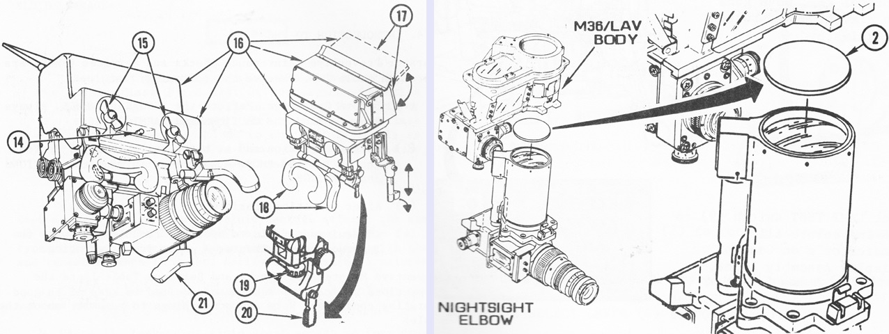
The M36/LAV is further detailed on the left, while on the right the nightsight elbow is shown being dismounted so the nightsight cover (2) can be removed. This cover was to be installed when the nightsight was not being used and before full daylight to prevent damage to the image intensifier tube. The key for the left image is: 14. Safety latch. 15. Periscope locking wing nuts. 16. Periscope mount M119. 17. Sight shield. 18. Headrest (brow pad). 19. Headrest adjusting knobs. 20. Headrest locking lever. 21. Sight shield handle. (Picture from TM 08594A-10/1 Operator's Manual Light Armored Vehicle LAV-25 (2320-01-123-1602) Turret PN 7566200-021.)
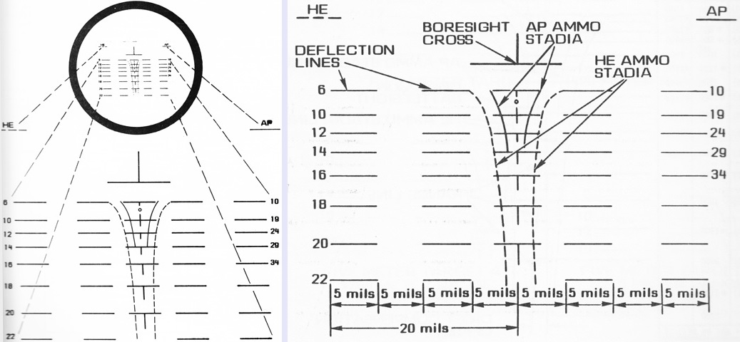
The daysight reticle pattern is sketched above. Horizontal deflection lines formed from 5-mil dashes and spaces totaled 20 mils to each side of the center range line. The numbers at the ends of the deflection lines indicated range in hundreds of meters. When properly aligned, the boresight cross indicated the centerlines of the weapons at 1,000m. The small circle under the topmost deflection line was the main gun battlesight circle. Stadia lines were used to help determine range, with the dashed stadia lines used with HE and the solid lines with AP. Range was determined by enclosing a 6-meter portion of the target between the stadia lines for the desired main gun ammunition type. Coaxial machine gun engagements instead used a 3.5-meter segment of the target. (Picture from TM 08594A-10/1 Operator's Manual Light Armored Vehicle LAV-25 (2320-01-123-1602) Turret PN 7566200-021.)
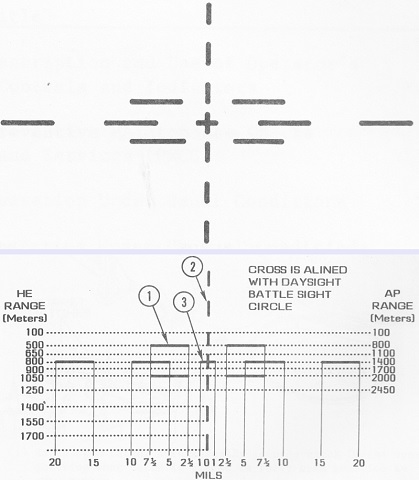
The nightsight reticle was composed of 5-mil horizontal deflection lines (1), 2-mil vertical range lines (2), and a 2-mil center cross (3). No stadia lines were present, but when the cross was placed on the center of impact at 800m, the ranges in the lower image could be used. (Picture from TM 08594A-10/1 Operator's Manual Light Armored Vehicle LAV-25 (2320-01-123-1602) Turret PN 7566200-021.)
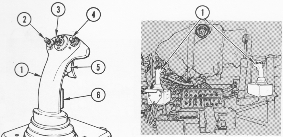
The commander and gunner were each provided with a hand control assembly that permitted control of turret azimuth, gun elevation, gun selection, main gun ammunition (HE or AP) and rate of fire (100 or 200 rounds per minute, or single shot) selection, and gun firing. The palm switch needed to be closed in order for the control handle to operate the turret or guns. If power drive was selected, only the commander's switches would work when the commander's palm switch was closed. If manual drive was selected, the commander's ammunition type, rate of fire, and gun selection switches would override the gunner's when the commander's palm switch was closed. The trigger had a guard that needed to be lifted before the trigger could be squeezed. Note also the weapon enclosure bag around the gun mount in the right drawing; this channeled turret exhaust air through and around the gun receivers in order to remove propellant gases from the vehicle interior.
1. Hand controls. 2. Main/coax switch. 3. 200/100/SS switch. 4. HE/AP switch. 5. Trigger. 6. Palm switch. (Picture from TM 08594A-10/1 Operator's Manual Light Armored Vehicle LAV-25 (2320-01-123-1602) Turret PN 7566200-021.)
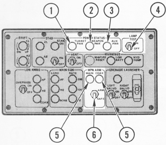
The control display assembly (CDA) was centered between the turret crewmen. 1. Turret power indicator. 2. Weapon power indicator. 3. Auxiliary power (gun sights, dome lights, NBC heaters) indicator. 4. Lamp test switch. 5. Main/coax armed indicators. 6. Weapon arm/safe switch.
The knob at the upper left is the elevation drift adjustment control, and below this is the azimuth drift adjustment. Just to the right of these are the elevation and azimuth stabilization indicators, which lit a steady red to indicate a malfunction, and flashed red to indicate the stabilization system was adjusting to the line of sight (e.g., due to fast turret movement or extreme vehicle motion). To the right of these indicators is the stabilization on indicator at the top and the stabilization on/off switch at the bottom. To the right of the stabilization switch is the turret ventilator switch. To the right of this switch is the misfire reset switch/indicator, which flashed to indicate a misfire or that the main gun bolt had stopped but was not in the sear stage. Pressing the button cycled the gun to the sear stage. To the right of this is the low battery indicator, which flashed when battery power was less than 19.5 volts. To its right is the hydraulic temperature indicator, which flashed to indicate the hydraulic system electric motor had overheated. At the lower left is the low ammo override switch, which, when placed in the spring-loaded on position, permitted firing when the selected ammunition ran low. The indicators to its right lit red to signify, from top to bottom, when approximately 12 rounds of AP, 25 rounds of HE, or 100 rounds of coax machine gun ammo remained. The column of indicators just to the right indicated, from top to bottom, AP ammo was selected, HE ammo was selected, and that the main gun bolt was in the sear position. To the right, top to bottom, are indicators for the selection of a firing rate of 200rpm, 100rpm, or single shot. The smoke grenade controls are at the lower right, with left or right salvo switches at the lower left (that could be simultaneously selected), a ready indicator above that lit green when weapon power was on and one or both grenade salvo switches were selected, and the grenade firing switch at the lower right. (Picture from TM 08594A-10/1 Operator's Manual Light Armored Vehicle LAV-25 (2320-01-123-1602) Turret PN 7566200-021.)
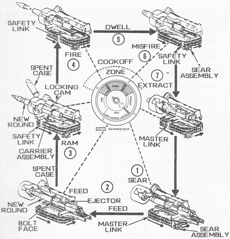
The firing cycle of the M242 is diagrammed here. The bolt position indicator in the center of the drawing would make a complete revolution for each round fired, normally starting and stopping at the SEAR position. The indicator stopping in the MISFIRE position denoted that a round in the chamber did not fire. If it stopped at any other position, the gun was jammed.
1. SEAR. The sear assembly engaged the master link and held the chain in position to begin the firing sequence. In single shot mode, the bolt remained in the sear position until the trigger was pulled. In 100rpm mode, the bolt remained in sear until a signal was received from the gun's logic. In 200rpm mode, the gun ran free and the rate of fire was determined by the speed of the driving motor. 2. FEED. The master link would move left to right across the carrier slide path to provide time for a new round to be positioned in the bolt face and for the spent casing to be positioned in front of the ejector. The feed rotor would sweep the spent case from the bolt and place the new round in the bolt face. 3. RAM. The carrier assembly would move forward, inserting the new round into the firing chamber. The spent case was ejected. The bolt was locked in the barrel when the carrier's locking cam rotated the bolt 15° counterclockwise. 4. FIRE. The firing pin was cocked and released after the bolt was locked. 5. DWELL. The master link moved right to left, providing dwell time for gases to escape down the gun barrel. 6. MISFIRE. If the round did not fire, the safety link would engage the sear assembly, stopping the chain and keeping the bolt locked. When the misfire reset button on the CDA was pressed, a 2.5-second delay was imposed before the trigger could again be activated to guard against open-bolt hangfire explosions. If the misfire occurred in single shot mode, the first trigger squeeze would return the bolt to the sear position, and firing could resume on the second trigger squeeze. The gun would resume firing at the selected rate with the first trigger pull when in 100rpm or 200rpm mode. 7. EXTRACT. As the bolt started to the rear, the locking cam rotated to unlock the bolt from the breech lugs. The bolt then continued to the rear and extracted the spent case. (Picture from TM 08594A-10/1 Operator's Manual Light Armored Vehicle LAV-25 (2320-01-123-1602) Turret PN 7566200-021.)
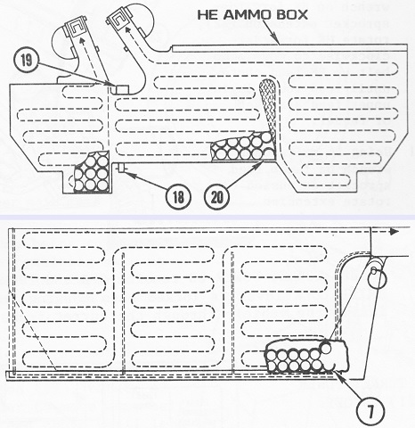
The main gun ready ammunition stowage is sketched at the top, with the smaller AP box at the left and the larger HE box to its right. At the bottom is the coaxial machine gun ammunition box, which held 400 rounds. 7. Single claw end of ammunition belt. 18. Low ammo reflector. 19. Low ammo sensor. 20. Single claw end of belt. (Picture from TM 08594A-10/1 Operator's Manual Light Armored Vehicle LAV-25 (2320-01-123-1602) Turret PN 7566200-021.)
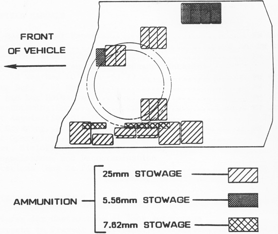
The location of stowed ammunition is the subject of this diagram. (Picture from TM 08594A-10/1 Operator's Manual Light Armored Vehicle LAV-25 (2320-01-123-1602) Turret PN 7566200-021.)
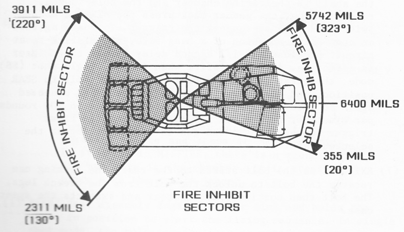
Firing inhibition zones were created around the hull hatches when the guns were fired electrically. If a rear hatch was open, the guns would not fire within 45° of the hull rear centerline, and a similar zone was set up for the driver's hatch when opened. The guns would also automatically elevate above -26 mils when traversed near an open hatch when the turret was in power mode. (Picture from TM 08594A-10/1 Operator's Manual Light Armored Vehicle LAV-25 (2320-01-123-1602) Turret PN 7566200-021.)
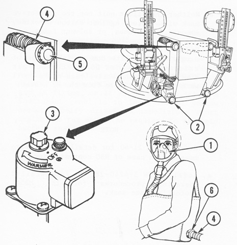
The vehicle was provided with an M13 NBC system, illustrated here for the turret crew. The system included the M1A1-19 precleaner and particulate filter assembly and M18 gas filters. Also present were the detector unit M43A1 and remote alarm M42. The system would not protect against CO, ammonia, or acid or solvent fumes. Frostbite could occur if used under arctic conditions, so the face mask hoses were not to be connected until the heaters were supplying warm air. 1. M25A1 face mask. 2. M3 heater. 3. Heater control knob. 4. Heater air hose breakaway socket. 5. Heater orifice. 6. Face mask cannister coupling. (Picture from TM 08594A-10/1 Operator's Manual Light Armored Vehicle LAV-25 (2320-01-123-1602) Turret PN 7566200-021.)
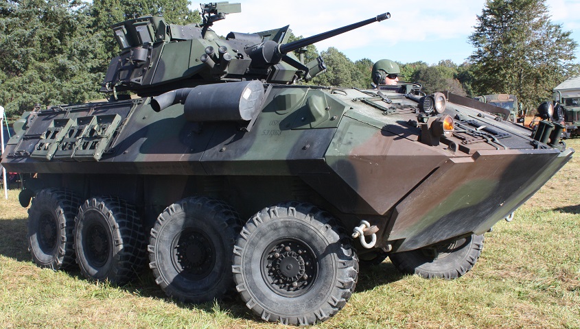
Visual differences of the LAV-25A2 compared to the vehicles above include the visibly thicker armor, larger tires, different exhaust muffler and outlet, and transparent armor for the turret crew. (Photo by Richard S. Eshleman.)
Details of the front suspension can be seen here, including the position of the spring, shock absorber, control arm, and brake line.
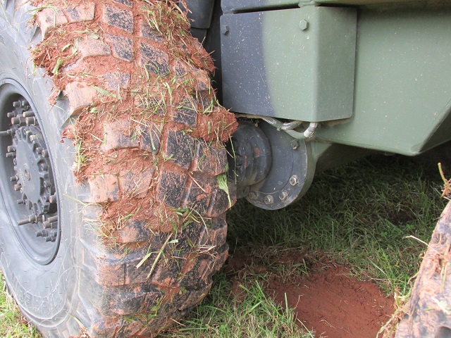
The rear torsion bar suspension is highlighted in this image.
Additional armor can be seen around the towing lug and headlight cluster. The self-recovery winch fairlead is on the opposite side of the bow in front of the left headlight cluster.
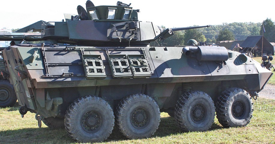
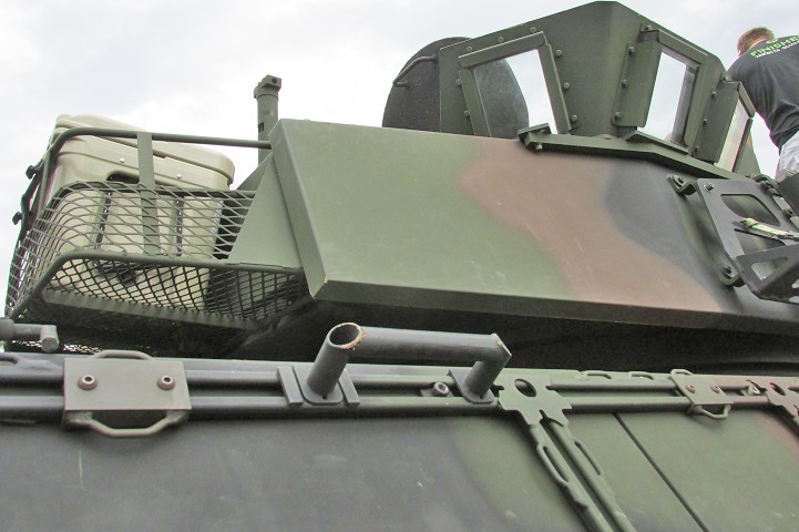
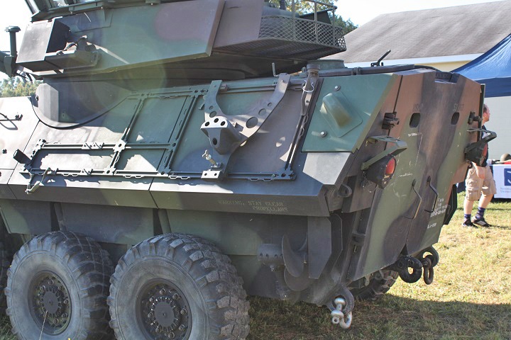
The thicker armor plates overlap the turret stowage basket, and the vision blocks in the hull side were covered. Stowage racks are mounted on the hull rear sides. (Photo by Richard S. Eshleman.)
This image provides a closer view of the turret side and transparent turret armor.
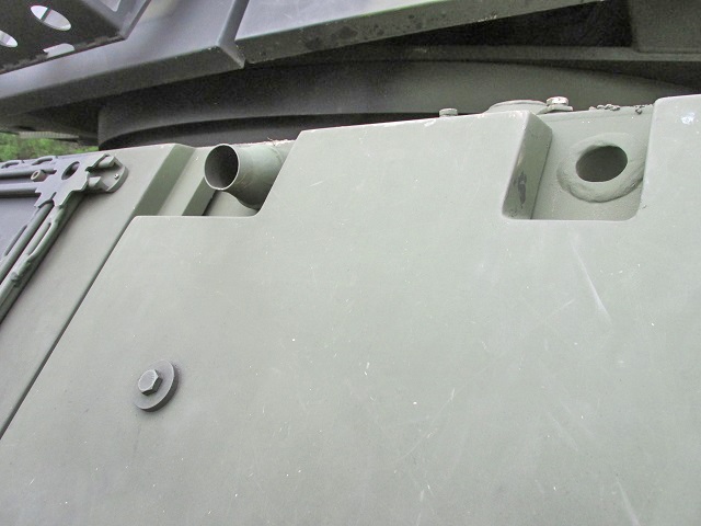
The applique armor had to leave apertures for necessities like the bilge pump outlet, for example.
The vision blocks in the rear doors are noticeably inset with the additional armor, and protection for the turret ring has been mounted on the hull side. A bracket for mounting a spare wheel can be seen on the rearmost stowage rack. (Photo by Richard S. Eshleman.)
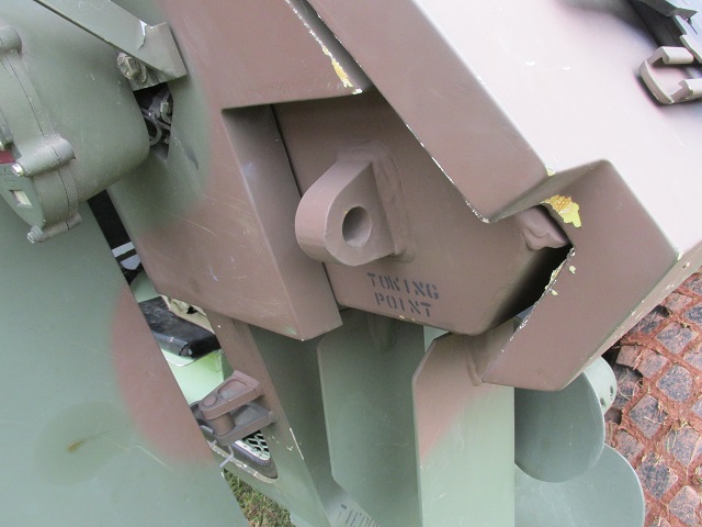
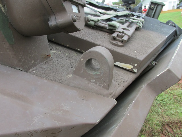
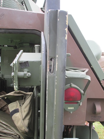
The rear towing lugs had cutouts in the applique armor as well. The rear light and its brush guard can be seen to the upper left.
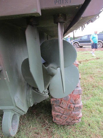
Two rudders were behind each propeller to steer the vehicle while afloat. A tie-down lug is welded to the hull below the propeller.
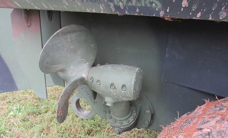
Further details of the propeller assembly are shown here.
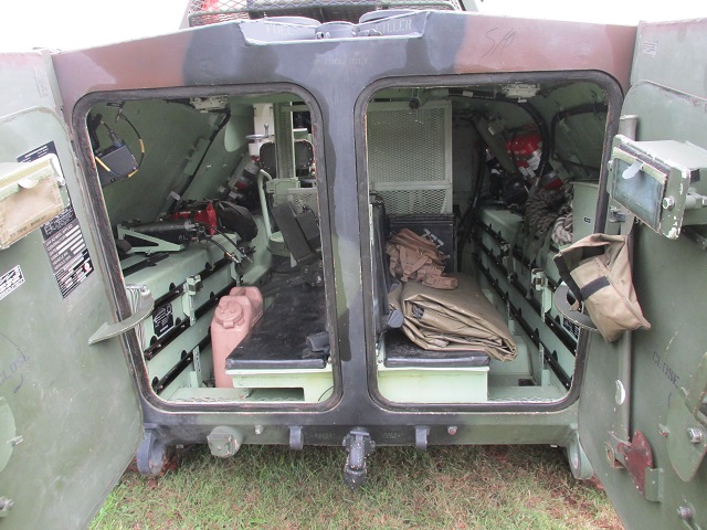
The rear doors are open on this machine. Vision blocks are installed in each of the doors, and brackets for tool stowage were provided on the right door. A towing pintle is centered below the doors, safety chain lugs flank the towing pintle, and a round intervehicle receptacle is under the left door.
An end-on view of the right door with its vision block is highlighted here.
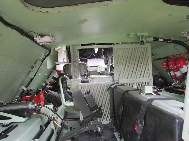
A view into another troop compartment is provided by this image. The turret floor can be seen ahead; the gunner's seat to the left is lower than the commander's on the right.
The opposite side of the troop compartment is shown here. The gunner's control can be seen in front of his seat.
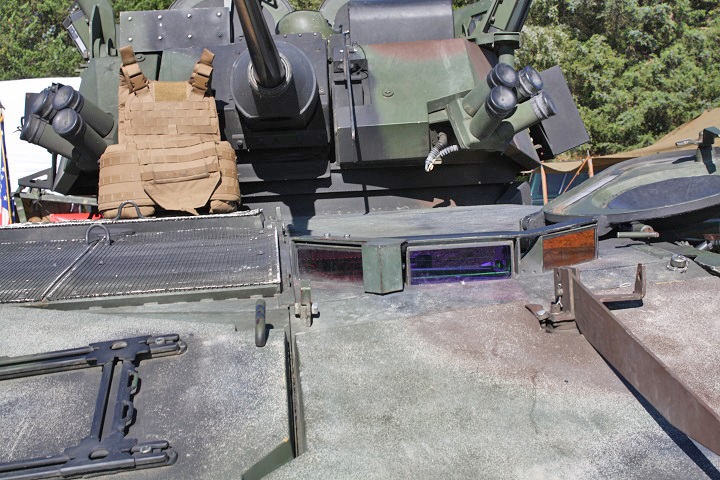
The thickness of the additional armor plating on the hull and turret can be gleaned from this image. The different turret sights can also be seen: contrasting to earlier vehicles, the gunner's now has a smooth, rounded cover plate while the commander's has a bolted, rectangular plate. (Photo by Richard S. Eshleman.)
