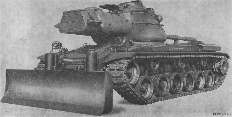
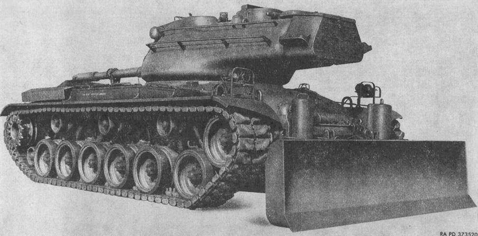
Tank Mounting Bulldozer M6.
When the M47 Patton 47 entered service, the M46 Patton's tank-mounting bulldozer M3 was modified to lower the time required to mount the assemblies as well as reduce its impact on ammunition stowage. This new version was standardized as the tank mounting earth moving bulldozer M6. (Picture from TM 9-7426 Operation and Organizational Maintenance and Field and Depot Maintenance Tank Mounting Earth Moving Bulldozer M6.)
The kit added 6,000lb (2,700kg) to the tank, including the hydraulic oil. With the main engine at 1,500rpm and the transmission in low gear, the tank's forward speed when bulldozing was 1-3mph (1.6-5kph), and the maximum recommended speed with the moldboard in the carry position was 15mph (24kph). (Picture from TM 9-7426 Operation and Organizational Maintenance and Field and Depot Maintenance Tank Mounting Earth Moving Bulldozer M6.)
The tank's angle of approach was reduced to 20° with the moldboard in the carrying position and 22° with the moldboard at its highest position. The cutting edge formed a 58° angle to the ground. At its highest position, the moldboard was 32" (81cm) above the ground, while the carrying position placed it at 31" (79cm) above the ground. The cutting edge could be lowered to 9 ¾" (24.8cm) below ground level. (Picture from TM 9-7426 Operation and Organizational Maintenance and Field and Depot Maintenance Tank Mounting Earth Moving Bulldozer M6.)
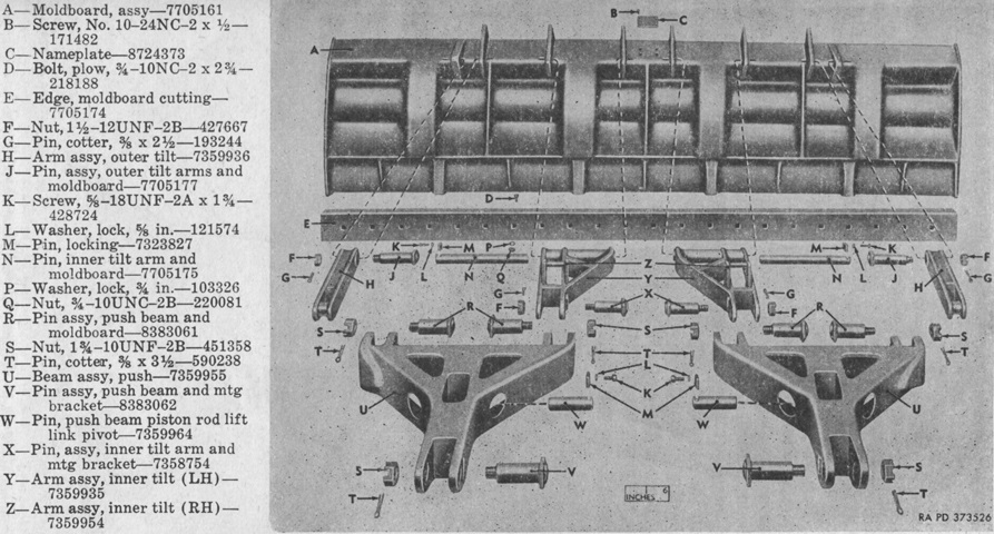
The moldboard, cutting edge, tilt arms, push beams, and attaching hardware are shown disassembled. The moldboard was 146 x 36 ¾" (371 x 93.35cm), and the cutting edge was 146 x 8 x ¾" (371 x 20 x 1.9cm). (Picture from TM 9-7426 Operation and Organizational Maintenance and Field and Depot Maintenance Tank Mounting Earth Moving Bulldozer M6.)
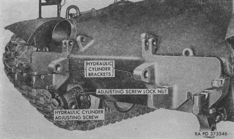
Before installation, it was necessary to remove the headlight assemblies and guards, the front fender sections, and the bow machine gun's exterior guard. The fenders would be reinstalled after modification, but the machine gun guard would be replaced by a new cover that allowed the hydraulics to be routed to the tank's exterior. Brackets for the hydraulic cylinders were welded to the hull front. (Picture from TM 9-7426 Operation and Organizational Maintenance and Field and Depot Maintenance Tank Mounting Earth Moving Bulldozer M6.)
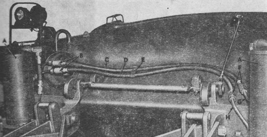
The hydraulic cylinders and exterior hoses and tubes are shown installed. A. Hydraulic cylinder. B. Hydraulic line tees. C. Left hydraulic cylinder upper hose. D. Left hydraulic cylinder lower hose. E. Hydraulic hose bracket. F. Hydraulic hose to tube reducer. G. Left cylinder upper tube. H. Left cylinder lower tube. (Picture from TM 9-7426 Operation and Organizational Maintenance and Field and Depot Maintenance Tank Mounting Earth Moving Bulldozer M6.)
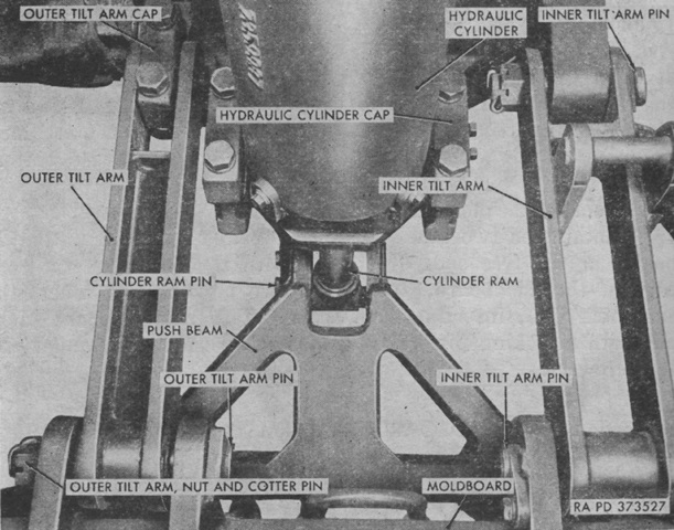
The quadrilateral linkages connecting the moldboard are detailed in this picture. (Picture from TM 9-7426 Operation and Organizational Maintenance and Field and Depot Maintenance Tank Mounting Earth Moving Bulldozer M6.)
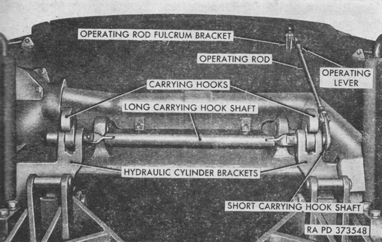
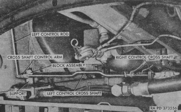
The moldboard carrying hooks, shafts, and operating lever are labeled in this image, and shielding for the hydraulic lines has been installed. Contrary to earlier tank mounting bulldozers, the carrying hooks operating lever was mounted on the outside of the hull. (Picture from TM 9-7426 Operation and Organizational Maintenance and Field and Depot Maintenance Tank Mounting Earth Moving Bulldozer M6.)
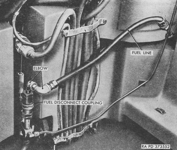
Modifications were also made to the engine in preparation for installation of the hydraulic pump. Two 90° elbows were added to the fuel line that connected the vehicle fuel tank to the inner fuel pump. (Picture from TM 9-7426 Operation and Organizational Maintenance and Field and Depot Maintenance Tank Mounting Earth Moving Bulldozer M6.)
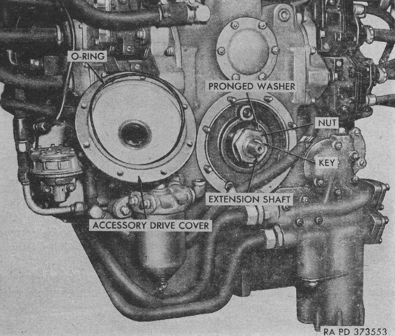
An extension shaft was installed on the main engine's power-take-off shaft in order to connect it via a flange to the propeller shaft that would power the hydraulic pump. (Picture from TM 9-7426 Operation and Organizational Maintenance and Field and Depot Maintenance Tank Mounting Earth Moving Bulldozer M6.)
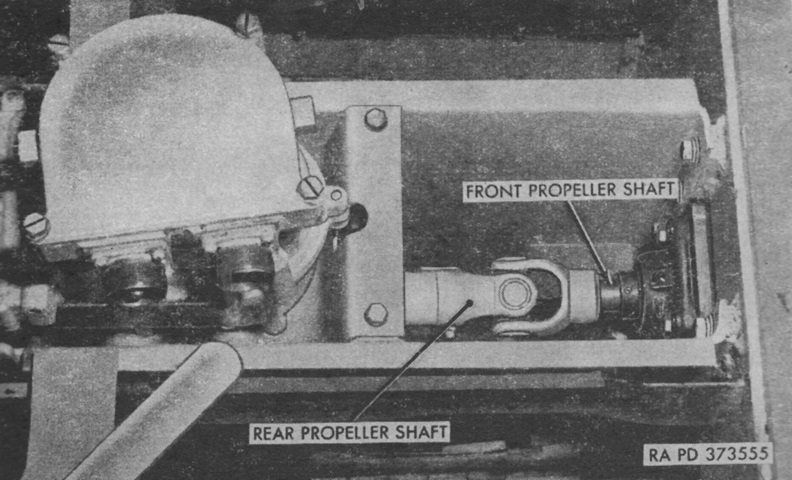
The propeller shaft that connected the hydraulic pump to the engine was composed of front and rear sections, and the joint of the two sections is shown here. The assembly on the left is the turret slip ring box. (Picture from TM 9-7426 Operation and Organizational Maintenance and Field and Depot Maintenance Tank Mounting Earth Moving Bulldozer M6.)
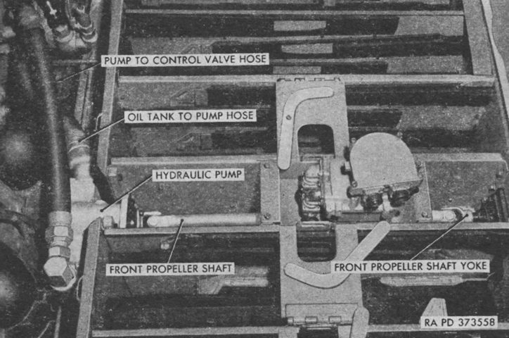
The hydraulic pump is shown installed and connected to the front propeller shaft. The fitting of the hydraulic pump bracket required cutting an opening into the front bulkhead in the shape of the bracket, and then attaching the bracket to the rear of the cut in the bulkhead. (Picture from TM 9-7426 Operation and Organizational Maintenance and Field and Depot Maintenance Tank Mounting Earth Moving Bulldozer M6.)
The control valve operating linkages were installed behind the drivers' seats and secured to the front bulkhead. The front of the hull is to the top of this image, and the driver's seat can be seen at the left behind one of the fixed fire extinguisher cylinders. (Picture from TM 9-7426 Operation and Organizational Maintenance and Field and Depot Maintenance Tank Mounting Earth Moving Bulldozer M6.)
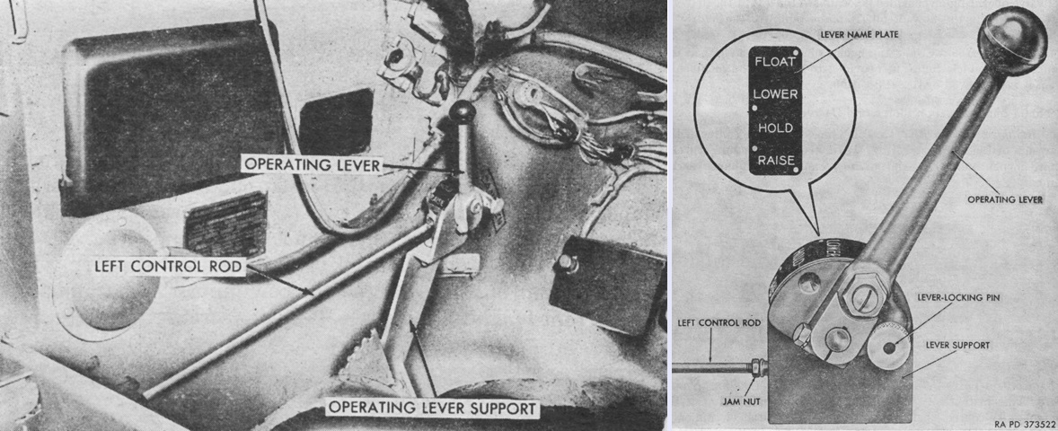
The control valve operating lever was mounted to the driver's left. A closer look at the lever is provided on the right. The lever could be placed in four positions: from front to rear, these were Float, Lower, Hold, and Raise. Lower and Raise executed their respective actions on the moldboard. Hold caused the moldboard to be locked at its current height. Float allowed the moldboard to be moved by external forces. If elevated when Float was selected, the moldboard would slowly settle onto the ground due to gravity. (Picture from TM 9-7426 Operation and Organizational Maintenance and Field and Depot Maintenance Tank Mounting Earth Moving Bulldozer M6.)
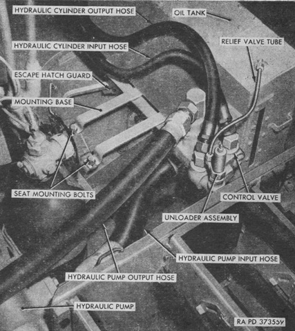
The hydraulic oil tank was installed on the assistant driver's side, using the hull pads for his seat. The tank was filled with 14 ½gal (54.9L) of seasonal transmission oil. (Picture from TM 9-7426 Operation and Organizational Maintenance and Field and Depot Maintenance Tank Mounting Earth Moving Bulldozer M6.)
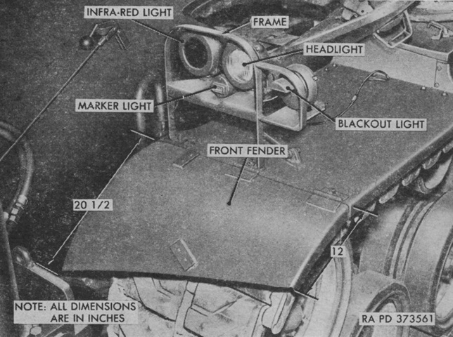
The front fenders were modified as shown, with the inner edge being 20 ½" (52.1cm) long and the outer 12" (30cm) long. New extended headlight frames were placed on the two inner fender hinges, and the headlights were reinstalled. (Picture from TM 9-7426 Operation and Organizational Maintenance and Field and Depot Maintenance Tank Mounting Earth Moving Bulldozer M6.)
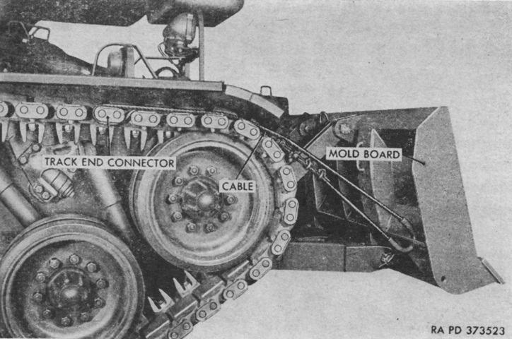
Rather than the hydraulic jacks found in previous tank mounting bulldozers, emergency lift cables were found on each rear side of the moldboard. In case of hydraulic failure, these cables were to be looped over an end connector on each track, and the tank would then reverse until the moldboard was high enough that the carrying hooks could be engaged. (Picture from TM 9-7426 Operation and Organizational Maintenance and Field and Depot Maintenance Tank Mounting Earth Moving Bulldozer M6.)
