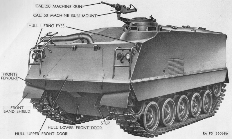
Armored Personnel Carrier M75.
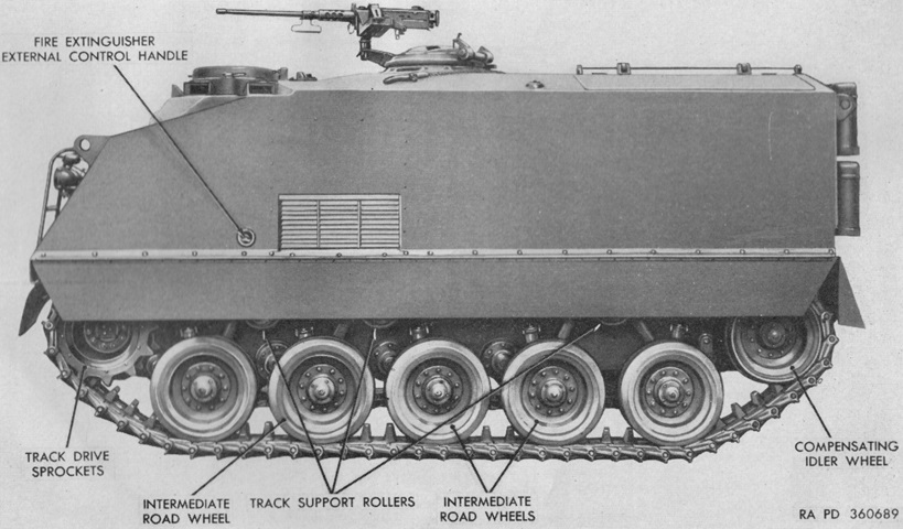
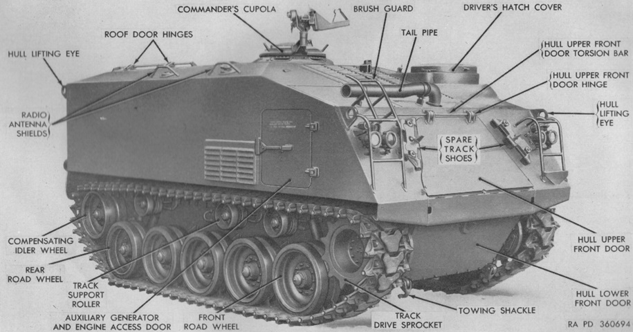
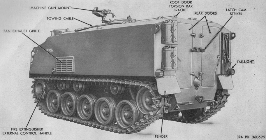
This machine is one of the earlier vehicles that retained sand shields and recesses for the external fire extinguisher controls, which can be seen just ahead of the fan exhaust grille on the side. The right headlight brushguard has been extended to protect the engine exhaust pipe, however. (Picture from TM 9-7418 C2 Operation and Organizational Maintenance Armored Full Tracked Personnel Carrier M75.)
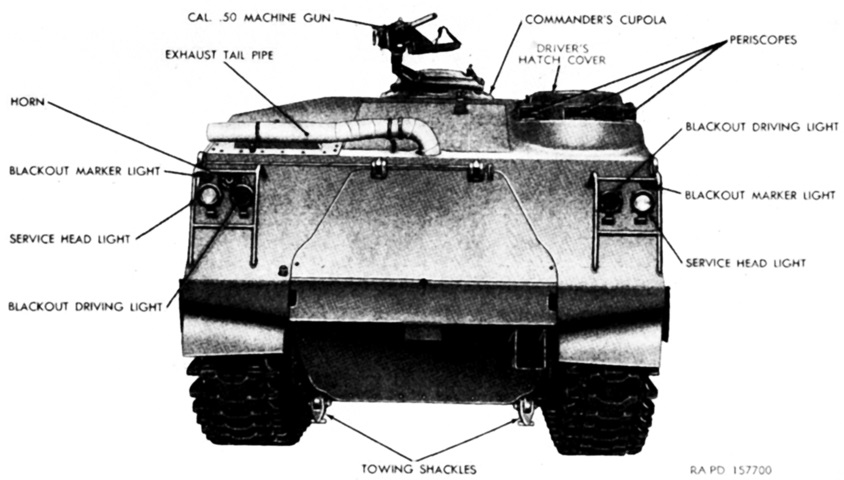
The early-production vehicle without the extended brush guard can be seen here head-on. (Picture from TM 9-755B Full-Track Armored Personnel Carrier T18E1.)
The left side of an early machine is shown in this image. (Picture from TM 9-7418 C2 Operation and Organizational Maintenance Armored Full Tracked Personnel Carrier M75.)
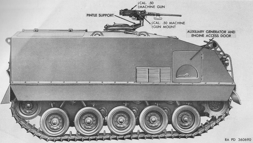
The auxiliary generator and engine access door as well as the four visible shock absorbers are hallmarks of an early-production machine. (Picture from TM 9-7418 C2 Operation and Organizational Maintenance Armored Full Tracked Personnel Carrier M75.)
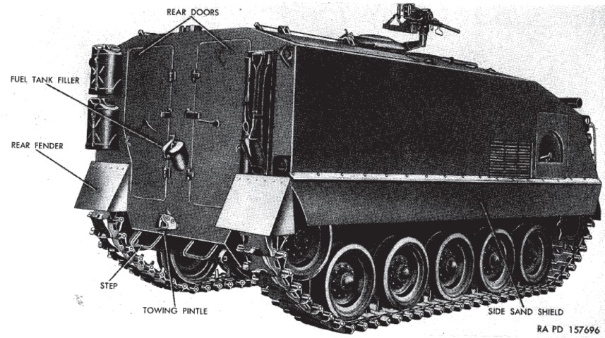
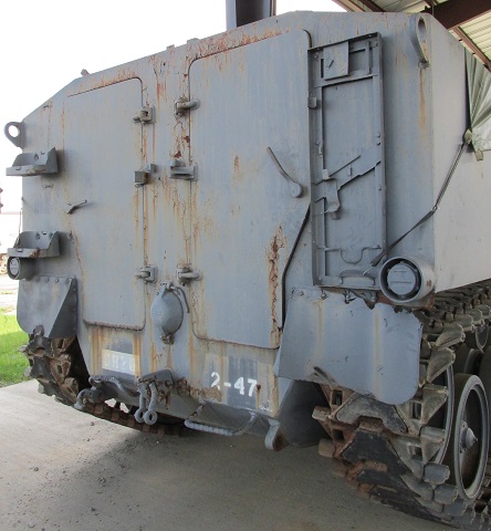
The two rear doors for infantry entry and exit are obvious in this rear view. Stowage for water cans and pioneer tools can also be seen on the vehicle's rear. Towards the front of the vehicle, the semicircular indentation housing a handle is the auxiliary generator and engine access door. This early machine features the spout-type rear fuel filler and the taillights, exterior fire extinguisher handles, and handle for the side engine access doors are all placed in indentations in the armor. Note the early placement of the handles for the rear doors. (Picture from TM 9-755B Full-Track Armored Personnel Carrier T18E1.)
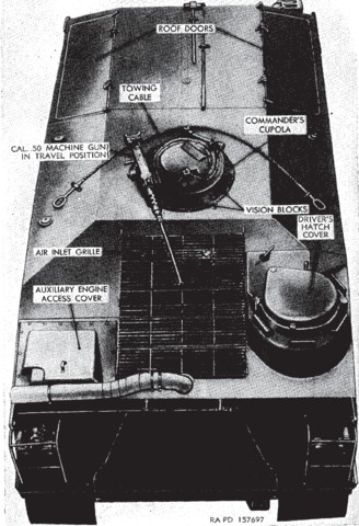
This upper view is of an early-production vehicle. The brush guard does not protect the engine exhaust pipe, and behind the exhaust pipe on the vehicle's right is the auxiliary engine access cover that was not needed on later vehicles that lacked the auxiliary generator. (Picture from TM 9-755B Full-Track Armored Personnel Carrier T18E1.)
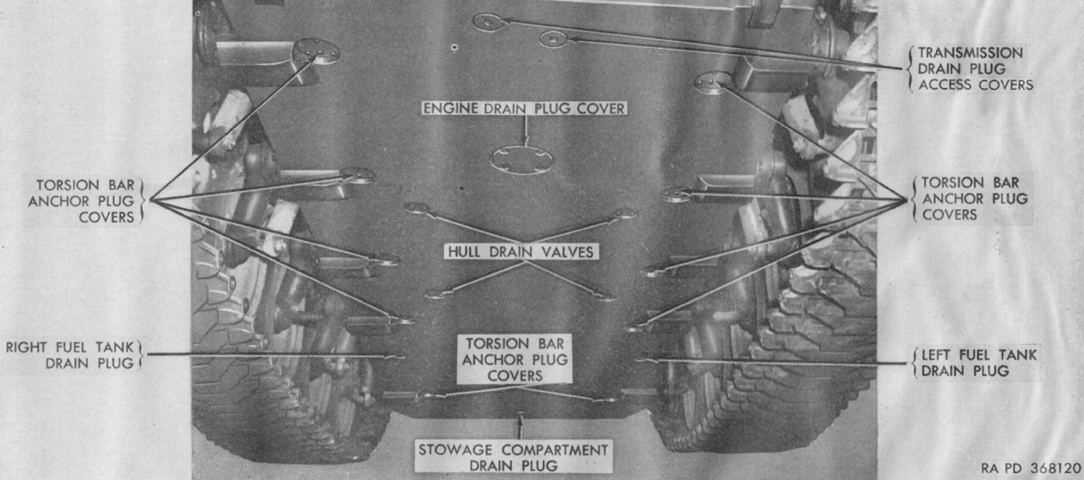
Early vehicles had drain valves in the engine compartment floor and the hull floor under the personnel compartment, as seen here. Later machines had two drain holes with plugs in the lower front of the hull. (Picture from TM 9-7418 C2 Operation and Organizational Maintenance Armored Full Tracked Personnel Carrier M75.)
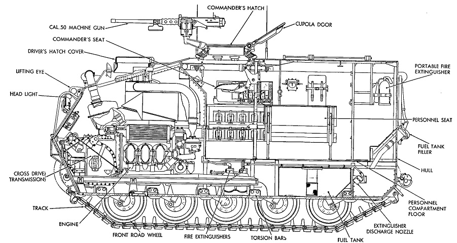
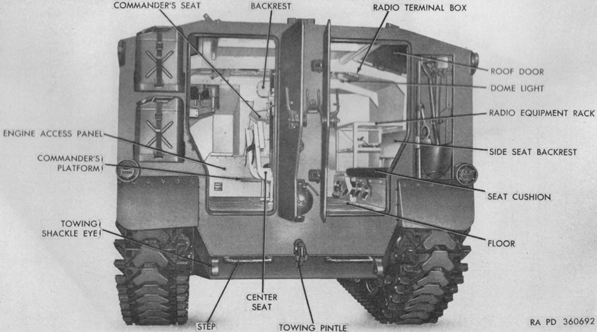
A cross-section of an early production machine is sketched here. (Picture from TM 9-755B Full-Track Armored Personnel Carrier T18E1.)
The older style auxiliary generator and engine access door has been replaced by a flat plate. (Picture from TM 9-7418 C2 Operation and Organizational Maintenance Armored Full Tracked Personnel Carrier M75.)
The revised fuel filler cover and taillight mounting can be seen on these examples. The mechanism for the rear doors has also been moved outboard of the centered mechanism found in earlier vehicles. Stowage is present on the vehicle on the right, and the securing straps for the fluid cans have worn into the paint.
Like the taillights, the fire extinguisher external control handle housing protrudes from the hull in this example. (Picture from TM 9-7418 C2 Operation and Organizational Maintenance Armored Full Tracked Personnel Carrier M75.)
With the deletion of the auxiliary generator and engine, the access panel behind the main engine exhaust pipe was also replaced by a flat plate. (Picture from TM 9-7418 C2 Operation and Organizational Maintenance Armored Full Tracked Personnel Carrier M75.)
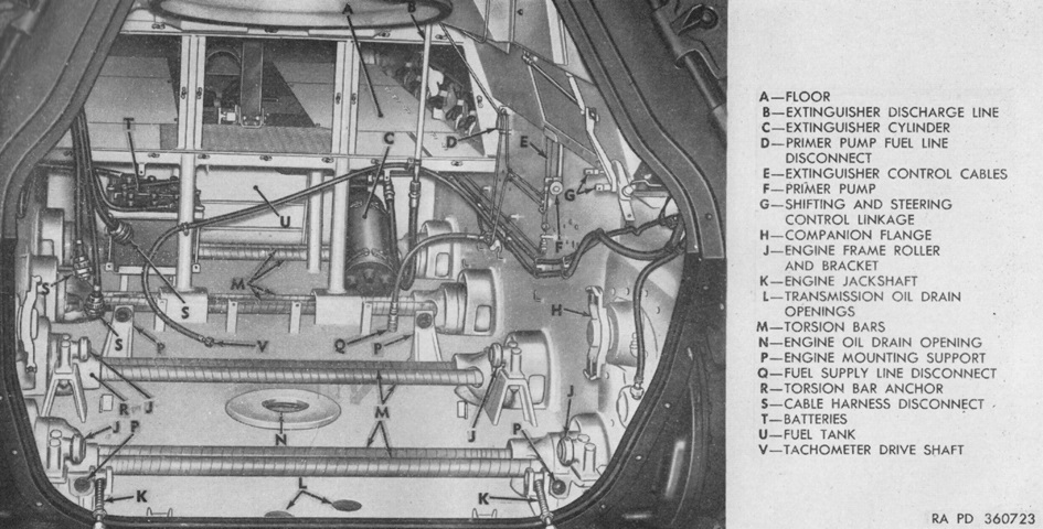
An interior view through the open rear doors of a late-production machine is provided here. (Picture from TM 9-7418 C2 Operation and Organizational Maintenance Armored Full Tracked Personnel Carrier M75.)
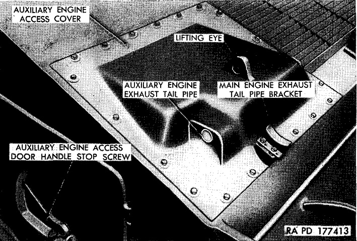
The cover for the auxiliary engine is the focus of this image. (Picture from TM 9-755B Full-Track Armored Personnel Carrier T18E1.)
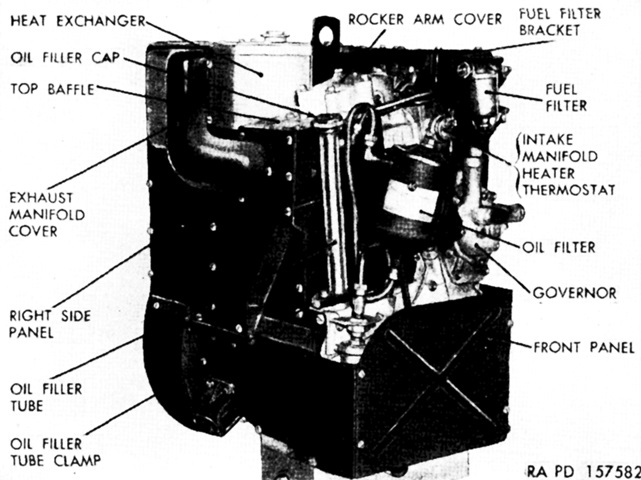
The auxiliary engine was a General Motors A-41-1 41in³- (670cm³)-displacement, 14.5-horsepower, single-cylinder, constant speed (3,100rpm), air-cooled, 4-cycle gasoline engine. Bore and stroke were 3.625" and 4" (9.208cm and 10cm), respectively, and its compression ratio was 6.6:1. It weighed 370lb (170kg) dry. The starter-generator was a Delco Products Division A-85-85 28 volt, 300 ampere, type II, direct-current, shunt-wound type with an automatic carbon stack regulator. It had an 8.4 kilowatt output. (Picture from TM 9-755B Full-Track Armored Personnel Carrier T18E1.)
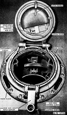
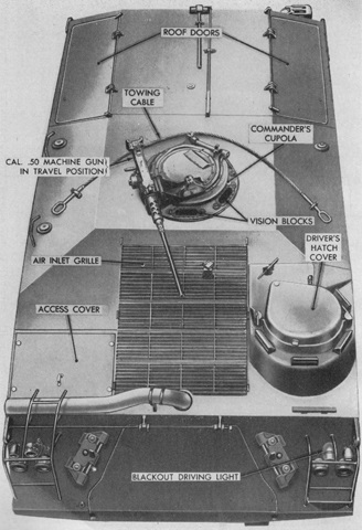
The commander's M2 cupola was provided with six stationary vision blocks for use when his door was closed. The pilot hole for the cupola was 29.75" (75.57cm) across, with the bolt circle being 31.50" (80.01cm) in diameter. The cupola weighed ~775lb (~352kg) with the machine gun and 105 rounds of ammunition mounted. When the machine gun was mounted, the door could only be opened when the weapon was placed in the travel position, which is illustrated in the view above. (Picture from TM 9-755B Full-Track Armored Personnel Carrier T18E1.)
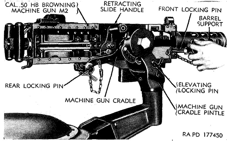
Details of the commander's machine gun mount are shown in this picture. (Picture from TM 9-755B Full-Track Armored Personnel Carrier T18E1.)
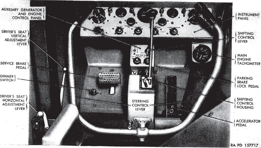
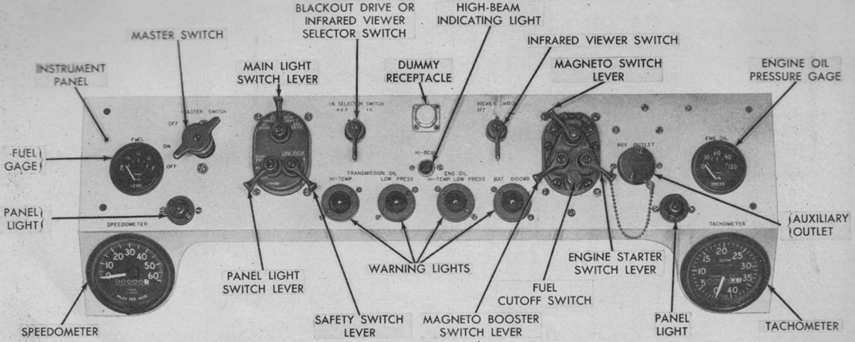
The large steering control lever pivoted as one unit, and driver's legs were placed between the arms of the control. The driver also had a horn switch just to the right of the right-hand steering lever arm. The large dial in the center of the instrument panel is the speedometer. (Picture from TM 9-755B Full-Track Armored Personnel Carrier T18E1.)
The driver's auxiliary generator and engine control panel disappeared with the deletion of that assembly. (Picture from TM 9-7418 C2 Operation and Organizational Maintenance Armored Full Tracked Personnel Carrier M75.)
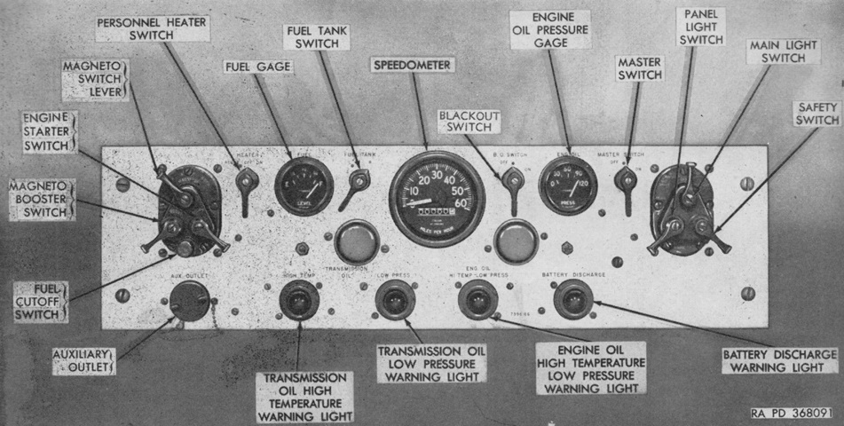
The driver's early instrument panel is labeled here. (Picture from TM 9-7418 C2 Operation and Organizational Maintenance Armored Full Tracked Personnel Carrier M75.)
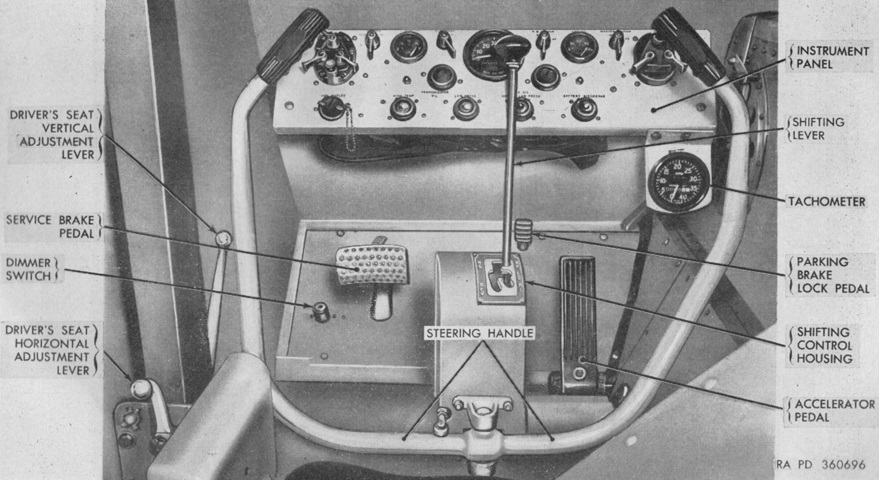
The driver's late instrument panel is labeled here. (Picture from TM 9-7418 C2 Operation and Organizational Maintenance Armored Full Tracked Personnel Carrier M75.)
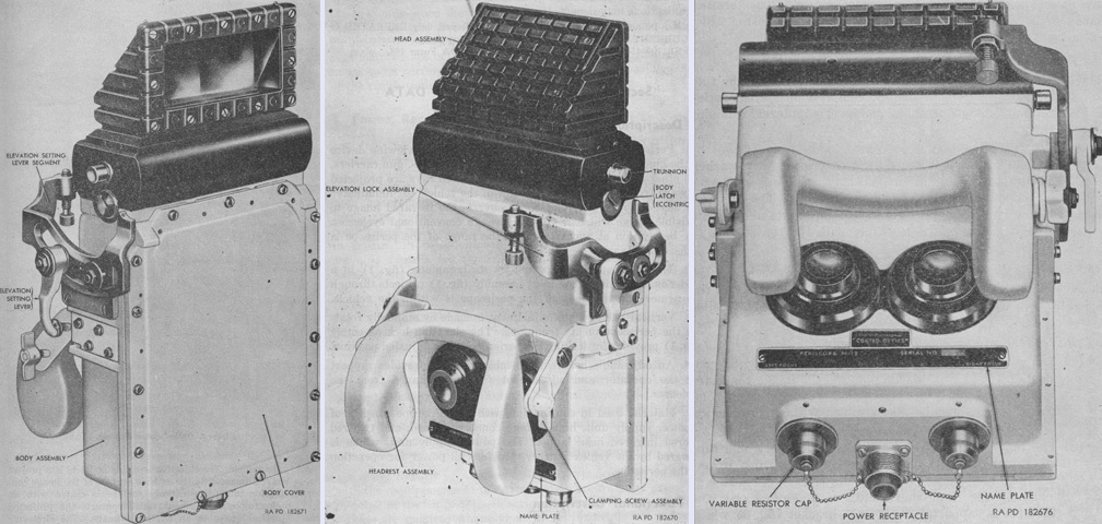
As seen in the late instrument panel, vehicles with serial numbers 377-1006 and 1327-1736 had a driver's hatch cover that was fitted with a quick-release assembly for an infrared periscope M19, seen here from the front, rear, and bottom. The 1x magnification M19 operated at 16,000 volts, had a 26.8° field of view, and had an 18-20 yard (16-18m) focal point. It was 6" (15cm) long, 8⅛" (20.64cm) wide, 15¼" (38.74cm) tall, and weighed 15lb 10 oz (7.0875kg). When installed, the hatch could not be swung to the open position. (Picture from TM 9-6059 Periscope M19.)
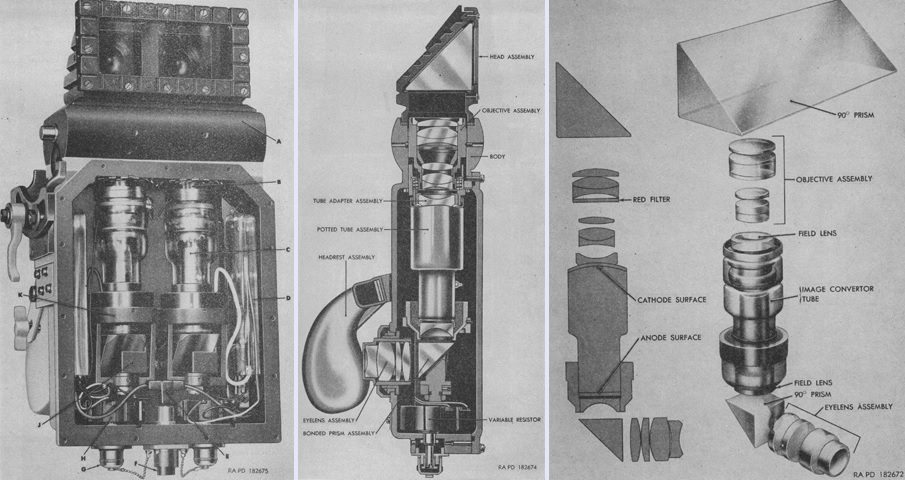
The periscope M19 is shown on the left with the front cover removed, in the center as a cross-section, and the optical system is diagrammed on the right. Infrared light was reflected to the objective through a 90° prism, which then projected a real image onto the cathode surface of the image converter tube. This surface was coated with an electropositive element that converted the projected optical image into an electronic image. This electronic image was projected onto a fluorescent screen at the base of the image converter tube, where it was viewed through the field lens, a 90° ocular prism, and the eyelens assembly.
The legend for the left image is: A. Body. B. Tube adapter assembly. C. Potted image convertor tube assembly. D. Terminal board assembly and housing. E. High voltage cable assembly. F. Power receptacle. G. Variable resistor bushing cap. H. Variable resistor assembly. J. Bonded prism assembly. K. Tube bracket. (Picture from TM 9-6059 Periscope M19.)
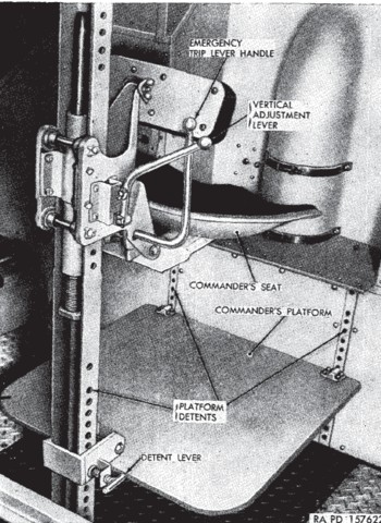
The vehicle commander's seat had a total height adjustment of 16.25" (41.28cm) available by pulling the adjustment lever to the left and raising or lowering the seat. The emergency trip lever allowed the seat to be folded down when not in use. The platform was also adjustable by moving it rearward to disengage the two front detents, engaging the desired front detents, and then locking the rear detent with the labeled detent lever. (Picture from TM 9-755B Full-Track Armored Personnel Carrier T18E1.)
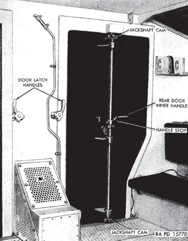
One of the early passenger compartment rear doors is shown here, along with part of the bench seat offered for the infantry. The labeled door latch handles were used to turn the cams for the outside door latches that hold the doors open when engaged. Three longitudinal seats were provided for passengers; the left and right were fixed, but the center seat was removable to provide access to the fuel tanks under the passenger compartment floor. (Picture from TM 9-755B Full-Track Armored Personnel Carrier T18E1.)
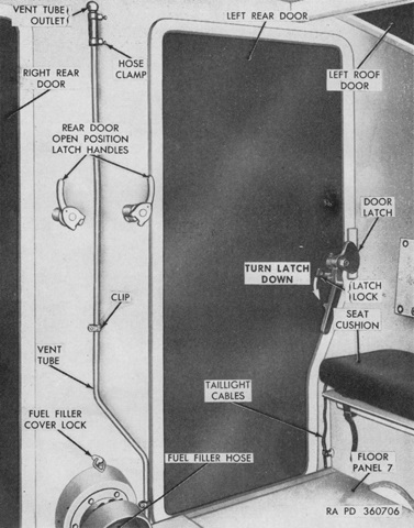
Late-production machines saw the cam system replaced with a simple latch at the outboard edge of the door. (Picture from TM 9-7418 C2 Operation and Organizational Maintenance Armored Full Tracked Personnel Carrier M75.)
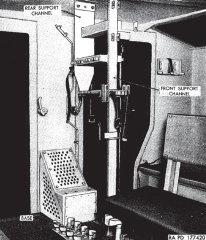
The armament rack installed in the rear of the vehicle could hold eight rifles or carbines, two .30cal machine guns, or a mortar. The rear of the rack provided stowage for a rocket launcher, or a steam condenser case and water chest for a .30cal heavy machine gun. The center bench seat is visible in front of the armament rack. The seat cushion on this bench could be swung up to access stowage inside the base of the seat. (Picture from TM 9-755B Full-Track Armored Personnel Carrier T18E1.)
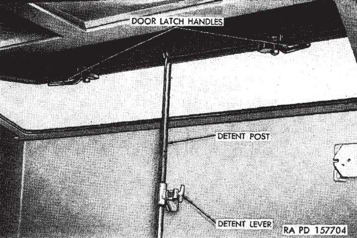
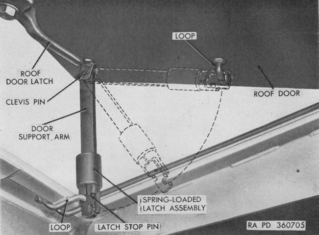
Two roof doors were provided for the passenger compartment, and these could be locked with 5" or 10" (13cm or 25cm) gaps or in the fully open position. The doors were locked in position by using the detent post. (Picture from TM 9-755B Full-Track Armored Personnel Carrier T18E1.)
The roof doors on late-production vehicles could only be locked in the open position. (Picture from TM 9-7418 C2 Operation and Organizational Maintenance Armored Full Tracked Personnel Carrier M75.)
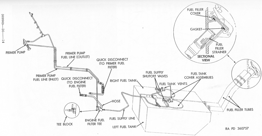
The fuel system of early vehicles used two ~75gal (~280L) rubber fuel tanks housed in metal cells on the hull floor at the back of the personnel compartment. Two filler tubes were found under the hinged cover on the vehicle rear. Each tank had a fuel pump in order to supply fuel to the carburetor, and a fuel tank switch on the instrument panel allowed either tank to be used. (Picture from TM 9-7418 C2 Operation and Organizational Maintenance Armored Full Tracked Personnel Carrier M75.)
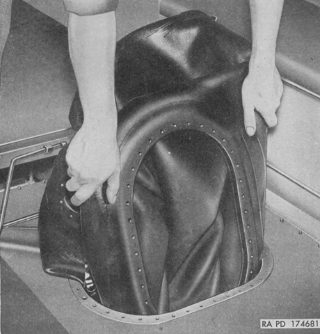
One of the rubber fuel tanks is shown here in the process of being removed through the fuel tank cover opening. (Picture from TM 9-7418 C2 Operation and Organizational Maintenance Armored Full Tracked Personnel Carrier M75.)
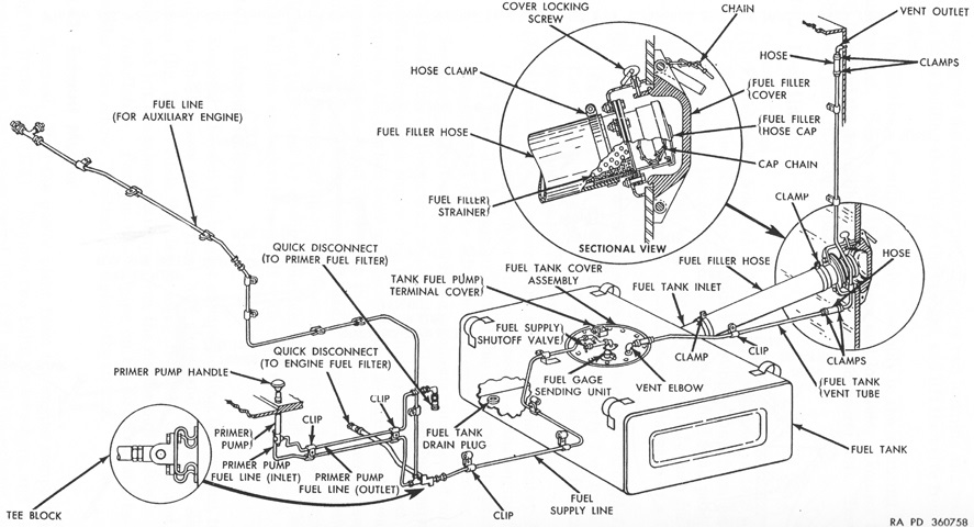
Late-production machines instead used a single metal 150gal (570L) fuel tank at the hull rear, which was filled by a single filler hose. A single fuel pump was used in the tank, and the superfluous tank selector switch on the driver's instrument panel was deleted. (Picture from TM 9-7418 C2 Operation and Organizational Maintenance Armored Full Tracked Personnel Carrier M75.)
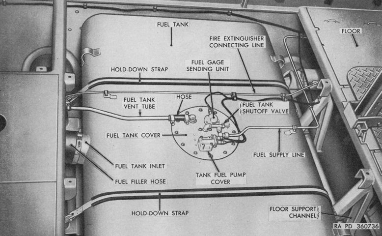
The larger metal fuel tank is shown here with the personnel compartment floor panels removed. (Picture from TM 9-7418 C2 Operation and Organizational Maintenance Armored Full Tracked Personnel Carrier M75.)
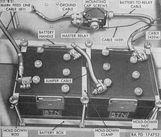
Two lead-acid type, 12-volt, 6-cell batteries were connected in series to create a 24-volt system. Each battery weighed 52lb (24kg) empty and 71lb (32kg) full, and they were kept in a battery box under the personnel compartment floor in the right front corner. On early vehicles, the negative terminal was connected to the master relay; this relay was operated by the master switch on the instrument panel. The master switch needed to be on, grounding the batteries' negative side via the master relay, before any electrical device would operate. The master switch had two connections to the batteries, one to the master relay, and a fourth connecting to a circuit breaker. (Picture from TM 9-7418 C2 Operation and Organizational Maintenance Armored Full Tracked Personnel Carrier M75.)
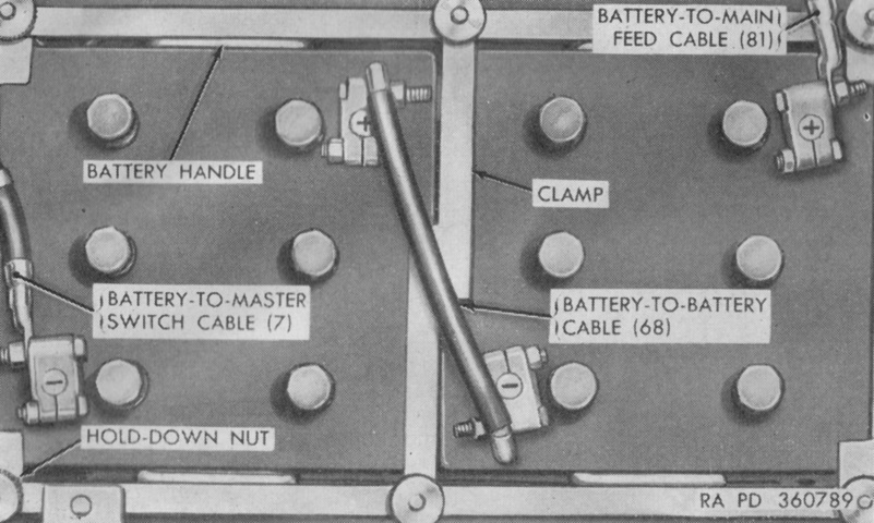
The negative terminals of batteries in late vehicles were connected to the master switch on the instrument panel, which connected the batteries' negative side to ground when the switch was on. In these vehicles, the master switch connected only to the batteries and to a ground strap. (Picture from TM 9-7418 C2 Operation and Organizational Maintenance Armored Full Tracked Personnel Carrier M75.)
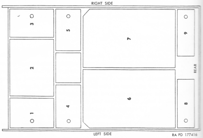
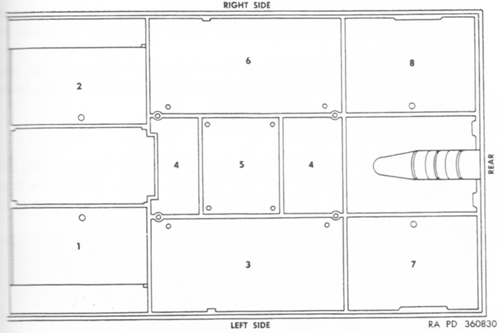
The personnel compartment floor in early vehicles was composed of nine removable panels. Panels 6 and 7 were bolted down, while the remainder could be lifted using integral fingerholes. Removing each panel granted access to: 1. Fixed fire extinguisher cylinders and control head, left rear hull drain valve and hull drain valve handle (if equipped), lower left portion of the engine's accessory end. 2. Lower central portion of the engine's accessory end. 2 and 3. Vehicle batteries, master relay, right rear hull drain valve, lower right portion of the engine's accessory end. 4 and 5. Stowage space. 6. Rear fire extinguisher discharge nozzle, left fuel tank, fuel tank shutoff valve, fuel pump cover assembly. 7. Right fuel tank, fuel tank shutoff valve, fuel tank cover assembly. 8 and 9. Stowage compartments. (Picture from TM 9-7418 C2 Operation and Organizational Maintenance Armored Full Tracked Personnel Carrier M75.)
The personnel compartment floor in late vehicles was composed of eight removable panels. Panels 1, 2, 7, and 8 were finger-lift panels, while the rest were bolted down. Removing each panel granted access to: 1. Forward fixed fire extinguisher cylinder and control head. 2. Storage batteries. 3, 4, 5, and 6. Fuel tank, with the fuel tank cover assembly under panel 5. 7. Stowage space, and the rear fixed fire extinguisher cylinder and the rear discharge nozzle. 8. Stowage space. (Picture from TM 9-7418 C2 Operation and Organizational Maintenance Armored Full Tracked Personnel Carrier M75.)
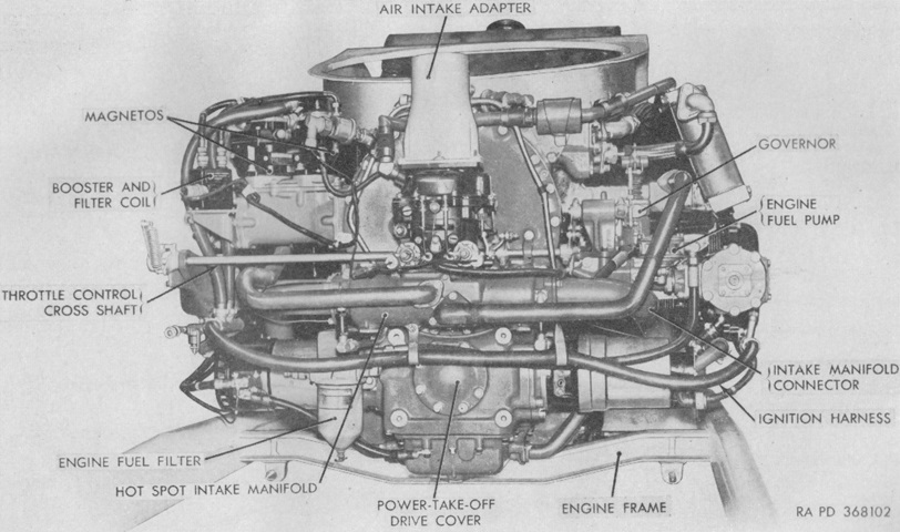
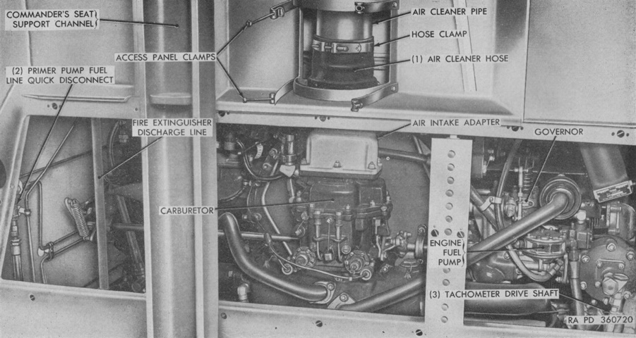
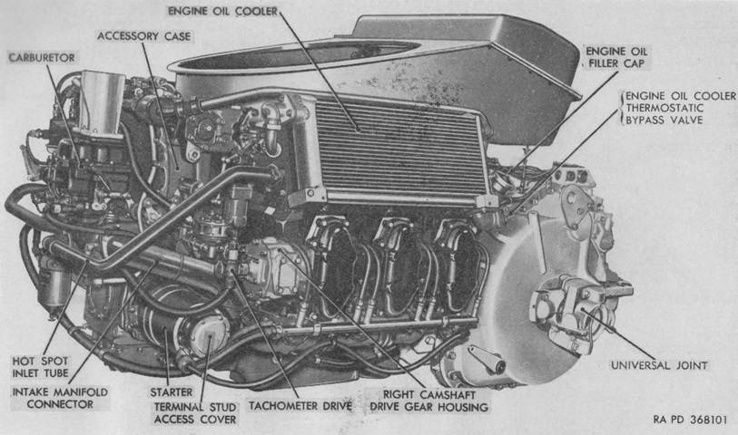
The engine's accessory end is labeled in this image. Somewhat confusingly, TM 9-7418 C2 considered the engine's accessory end as the rear and flywheel end as the front, while TM 9-1755BB/TO 19-100AD-1 C2 considered the accessory end as the front and the flywheel end as the rear. Both manuals determined the engine's left and right sides by viewing the engine from the accessory end to the flywheel end. (Picture from TM 9-7418 C2 Operation and Organizational Maintenance Armored Full Tracked Personnel Carrier M75.)
Some differences introduced during the production run can be seen here. Starting with engine serial number 146, magnetos with internal oilers and steel cams replaced the previous magnetos with external oilers and Buna cams. Engine serial number 219 began the use of a shorter flexible line that connected the vacuum heat control to the cylinder number 5 intake manifold section instead of to the carburetor. Engine serial number 457 was the first to use an oil pressure regulating valve in the engine hydraulic governor system. A 148°F (64.4°C) oil cooler thermostatic bypass valve replaced the previous 185°F (85.0°C) model beginning with engine number 1273. Engine serial number 1531 saw the introduction of new primer filters. (Picture from TM 9-7418 C2 Operation and Organizational Maintenance Armored Full Tracked Personnel Carrier M75.)
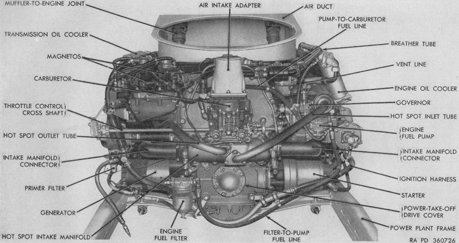
Another view of a later accessory end is provided in this picture. Cylinders were numbered 1, 3, and 5 on the right when viewed from the accessory end, and 2, 4, and 6 on the left when viewed from the accessory end. Firing order was 1-6-3-2-5-4. (Picture from TM 9-1755BB/TO 19-100AD-1 C2 6-Cylinder, Horizontally-opposed, Air-cooled Gasoline Engine (Continental Model AO-895-4).)
The accessory end of the engine is seen here from the passenger compartment after its access panels have been removed. (Picture from TM 9-7418 C2 Operation and Organizational Maintenance Armored Full Tracked Personnel Carrier M75.)
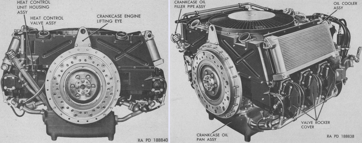
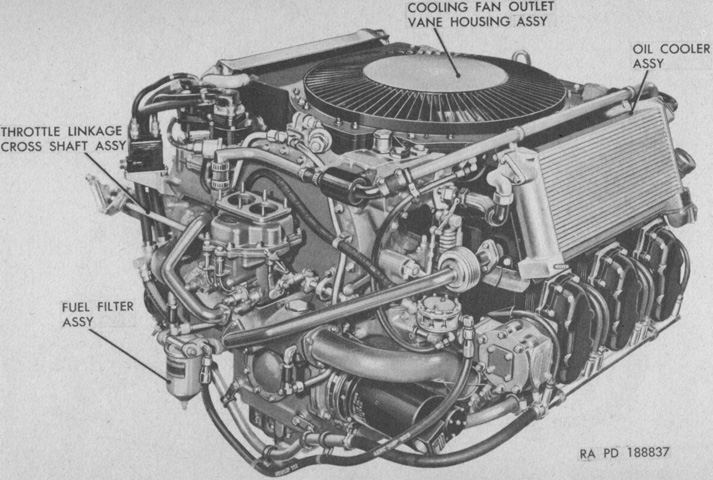
The flywheel end of the engine is labeled in these two views. (Picture from TM 9-1755BB/TO 19-100AD-1 C2 6-Cylinder, Horizontally-opposed, Air-cooled Gasoline Engine (Continental Model AO-895-4).)
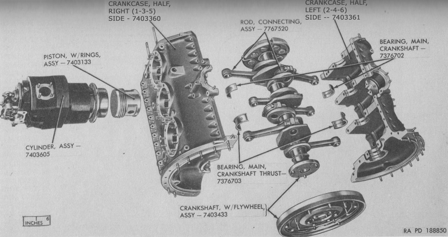
The engine crankcase has been disassembled into its major components, illustrating the opposed nature of the cylinders. When viewed from the accessory end, the crankshaft rotated clockwise, while both camshafts rotated counterclockwise. (Picture from TM 9-1755BB/TO 19-100AD-1 C2 6-Cylinder, Horizontally-opposed, Air-cooled Gasoline Engine (Continental Model AO-895-4).)
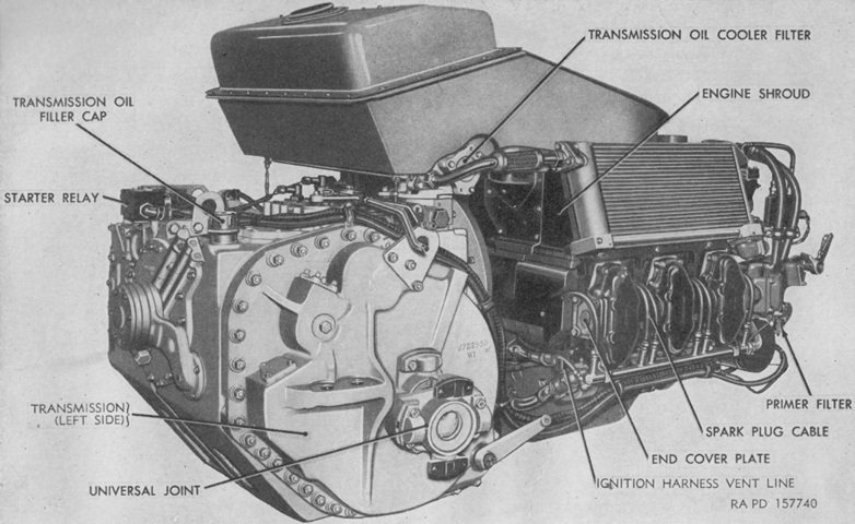
The M75's combined engine and transmission are pictured here. The engine had overhead valves actuated by a single overhead camshaft for each cylinder bank. A single Stromberg float-type double-venturi downdraft carburetor was mounted. Bore and stroke were both 5.75" (14.6cm), its compression ratio was 6.5:1, and the engine could hold 12 gallons (45L) of oil. (Picture from TM 9-7418 C2 Operation and Organizational Maintenance Armored Full Tracked Personnel Carrier M75.)
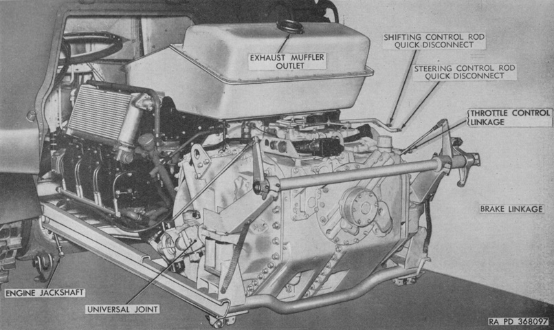
The power plant is seen from the right rear. The engine's dry weight with the flywheel and all accessories was 1,856lb (841.2kg). Including the flywheel assembly, the engine's length was 49.24" (125.1cm), width was 50.72" (128.8cm), and height was 36.96" (93.88cm). (Picture from TM 9-7418 C2 Operation and Organizational Maintenance Armored Full Tracked Personnel Carrier M75.)
The engine and transmission are seen from the front in this picture. The transmission weighed 1,945lb (882.3kg), was 34-5/32" (86.75688cm) long, 33½" (85.1cm) tall, and 44¾" (113.7cm) wide. (Picture from TM 9-7418 C2 Operation and Organizational Maintenance Armored Full Tracked Personnel Carrier M75.)
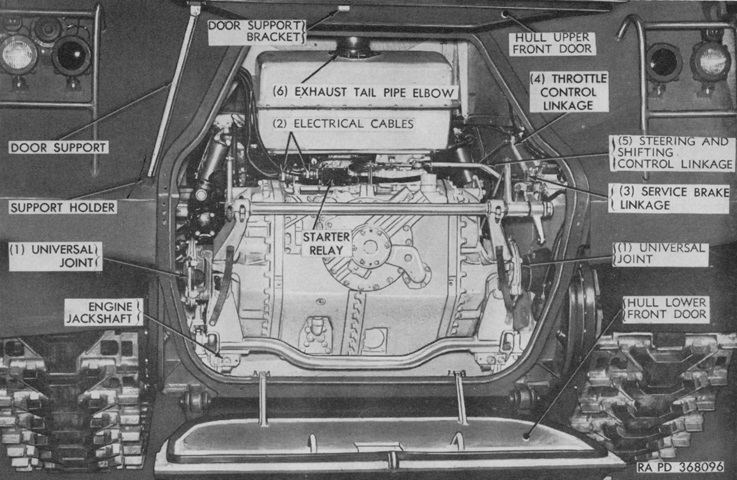
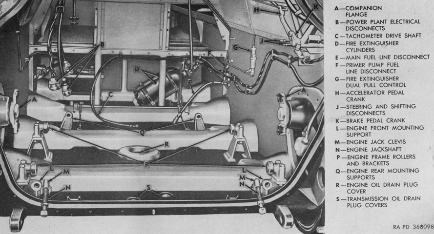
The hull front doors have been opened on this early machine, showing an interior view of the installed engine and transmission. The numbers refer to steps in the powerplant removal process. (Picture from TM 9-7418 C2 Operation and Organizational Maintenance Armored Full Tracked Personnel Carrier M75.)
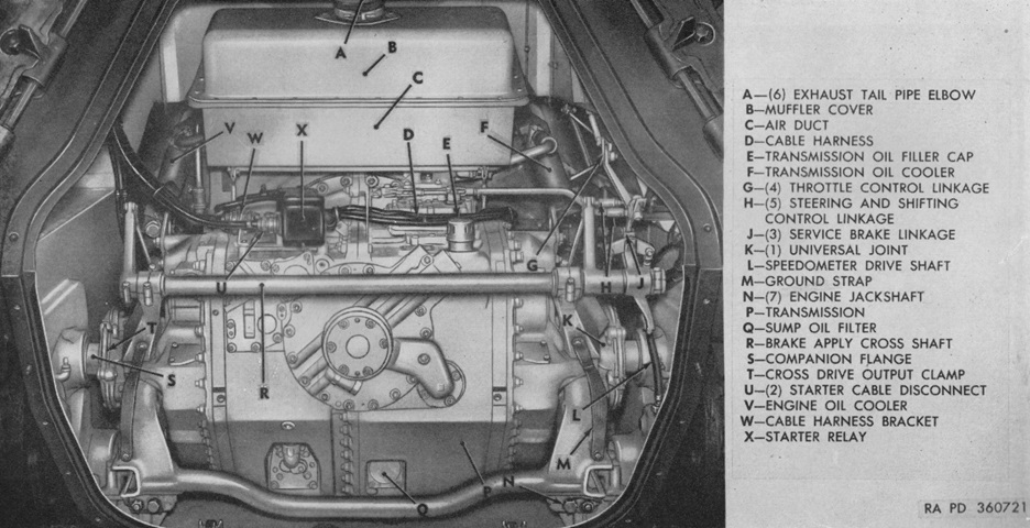
The same view is provided with a late vehicle. (Picture from TM 9-7418 C2 Operation and Organizational Maintenance Armored Full Tracked Personnel Carrier M75.)
The powerplant was mounted on rollers so that it could be pulled from the engine compartment for maintenance or testing, although it was recommended to rest the forward end of the engine frame on blocks after sliding it out of the engine compartment. With electrical jumper cables and a flexible fuel line attached, the engine could be operated while outside of the hull. (Picture from TM 9-7418 C2 Operation and Organizational Maintenance Armored Full Tracked Personnel Carrier M75.)
The engine and transmission have been removed from this early vehicle. Note the torsion bar housings cast into the hull. (Picture from TM 9-7418 C2 Operation and Organizational Maintenance Armored Full Tracked Personnel Carrier M75.)
The same view into a late-production machine reveals that the torsion bar housings were eliminated. (Picture from TM 9-7418 C2 Operation and Organizational Maintenance Armored Full Tracked Personnel Carrier M75.)
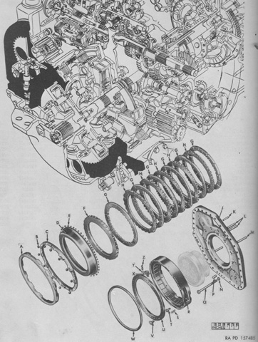
An exploded diagram of the right brake assembly is sketched here, with the transmission interior visible in the background. A. Ring. B. Ball. C. Ring. D. Ring. E. Ball. F. Plate. G. Disk. H. Disk. J. Plate, assy. K. Pin. L. Tube. M. Pin. N. Washer. P. Pin. Q. Bolt. R. Plate, assy. S. Spring. T. Bolt. U. Plate. V. Screw. W. Seal. X. Indicator. Y. Screw. Z. Washer. (Picture from ORD 9 SNL G-260 List of All Service Parts of Carrier, Personnel, Full-tracked, Armored, M75.)
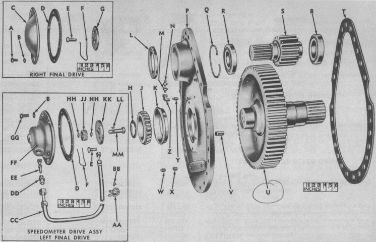
The final drive has been disassembled into its parts. A. Bolt. B. Washer. C. Cap. D. Gasket. E. Screw. F. Wire. G. Plate. H. Shim. J. Cone. K. Cup. L. Seal. M. Bushing. N. Valve. P. Cover. Q. Ring. R. Bearing. S. Gear. T. Gasket. U. Gear. V. Pin. W. Plug. X. Plug. Y. Plug. Z. Elbow. AA. Clamp. BB. Bolt. CC. Shaft. DD. Sleeve. EE. Gear. FF. Housing. GG. Bolt. HH. Ring. JJ. Gear. KK. Retainer. LL. Key. MM. Shaft. (Picture from ORD 9 SNL G-260 List of All Service Parts of Carrier, Personnel, Full-tracked, Armored, M75.)
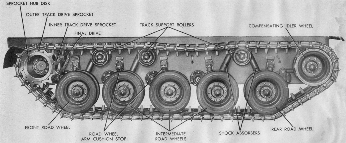
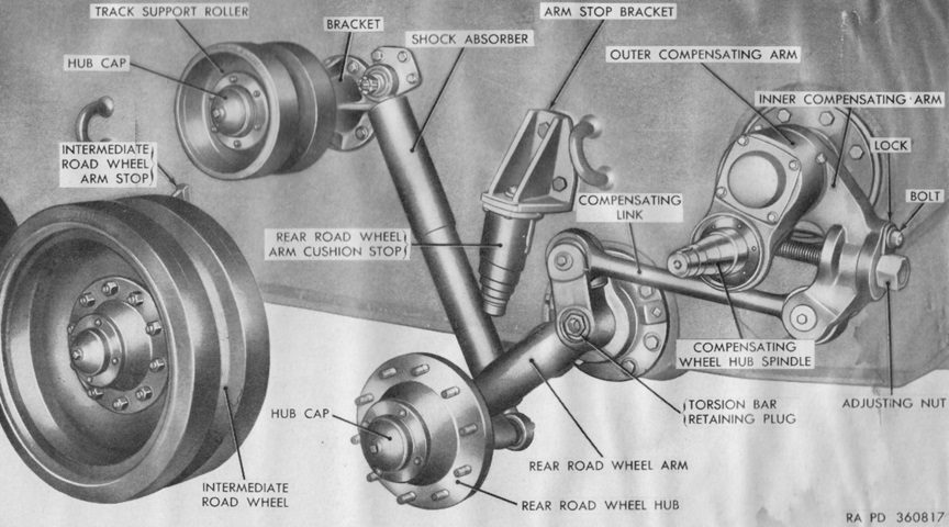
The suspension of an early-production machine is labeled. Note the four shock absorbers as well as the reversed orientation of the rear road wheel swing arm compared to that found on the preceding wheel stations. (Picture from TM 9-7418 C2 Operation and Organizational Maintenance Armored Full Tracked Personnel Carrier M75.)
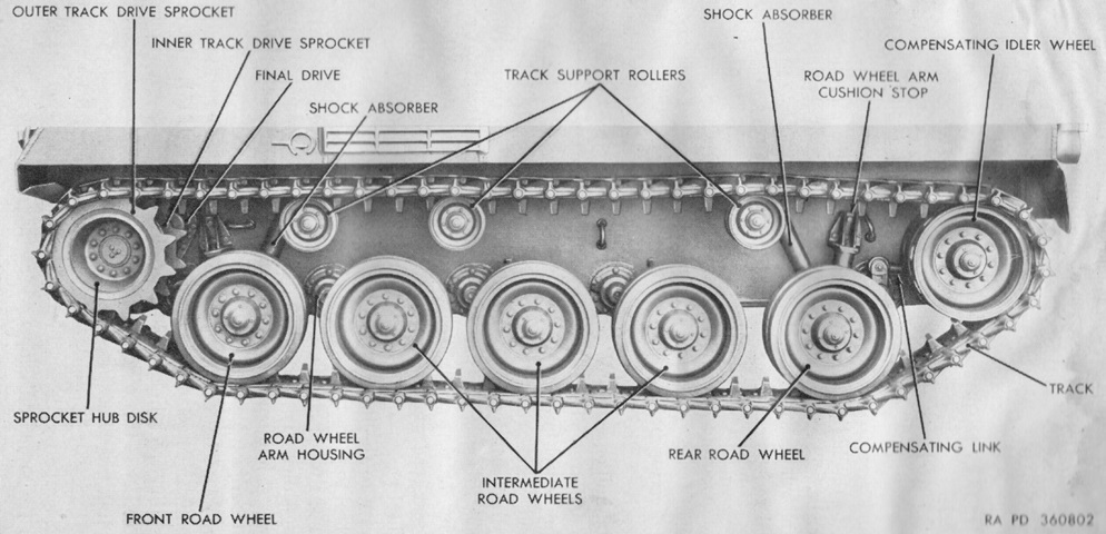
The changes made to the late-production suspension can be gleaned from a comparison with the above image. The central shock absorbers were deleted, and the volute bumper springs for the inner wheels were replaced with fixed steel stops, which are hidden by the road wheels. (Picture from TM 9-7418 C2 Operation and Organizational Maintenance Armored Full Tracked Personnel Carrier M75.)
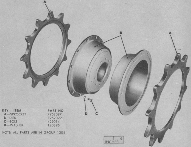
A disassembled drive sprocket is illustrated in this image. (Picture from ORD 9 SNL G-260 List of All Service Parts of Carrier, Personnel, Full-tracked, Armored, M75.)
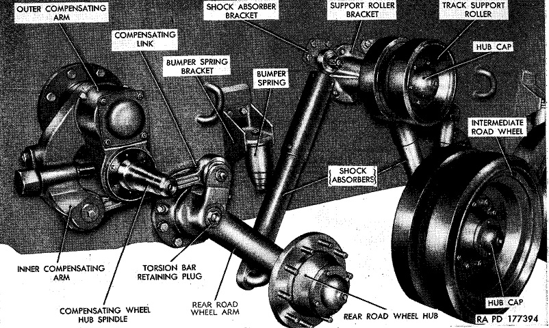
Track tension was increased or decreased by adjusting the inner compensating arm, and the rear compensating idler was able to keep the track sufficiently tensioned while navigating terrain. Movement of the rear road wheel arm was transmitted to the inner compensating arm via the compensating link. When the rear road wheel passed over an obstacle, the upward movement of its arm swung the idler to the rear, keeping the track tensioned. As the rear road wheel arm returned to its rest position, the idler was brought forward again. (Picture from TM 9-755B Full-Track Armored Personnel Carrier T18E1.)
A late-production idler wheel compensating assembly is shown here. Note the small steel road wheel arm stop behind the intermediate road wheel instead of the earlier volute spring. (Picture from TM 9-7418 C2 Operation and Organizational Maintenance Armored Full Tracked Personnel Carrier M75.)
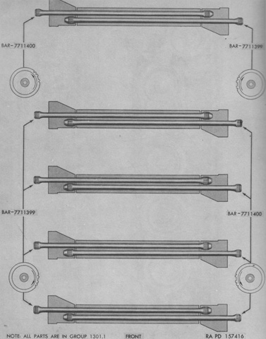
As seen in the preceding two images, the rear road wheels were mounted on leading arms while the other road wheels were on trailing arms. Because of this, there was a larger space between the rear road wheel torsion bars compared to the closer grouping of the four sets of torsion bars for the forward wheels (not to scale in this image). Also, due to the reversed rotation of the rear wheels' leading arms, torsion bar 7711400 was behind 7711399 for the rear wheels, in contrast to the other wheels where this positioning was the opposite. (Picture from ORD 9 SNL G-260 List of All Service Parts of Carrier, Personnel, Full-tracked, Armored, M75.)
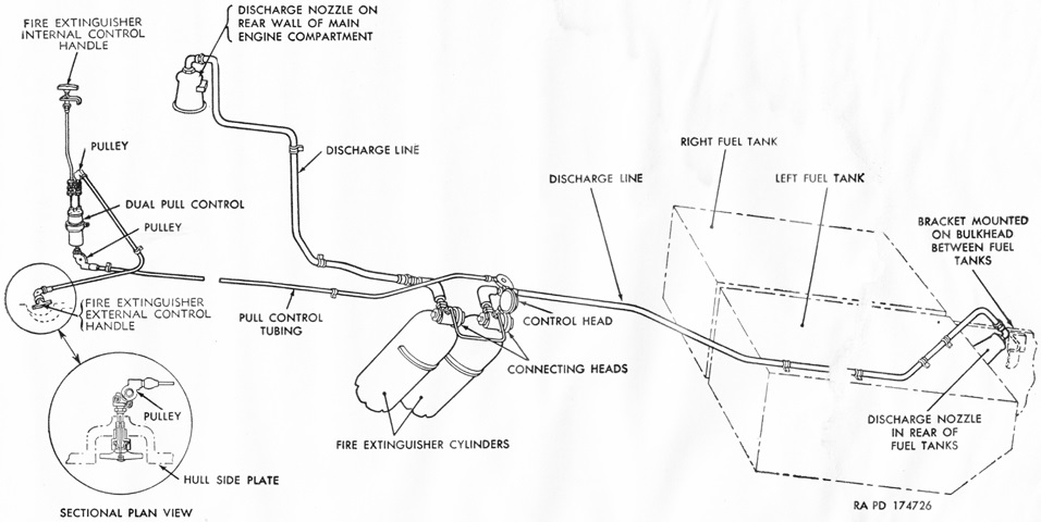
The fixed fire extinguisher system was comprised of two 10lb (4.5kg) CO2 cylinders routed to the engine and fuel tank compartments. Activation handles were present on the outside of the hull near the front left side and to the driver's right rear. Each handle would discharge both cylinders. A schematic of the fixed system used in vehicles serial numbers 7-376 by International Harvester and 1007-1326 by FMC is provided here. In addition, a portable 4lb (2kg) CO2 extinguisher was stowed at the right rear corner of the passenger compartment. (Picture from TM 9-7418 C2 Operation and Organizational Maintenance Armored Full Tracked Personnel Carrier M75.)
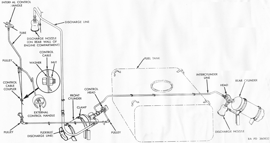
The layout of the fixed fire extinguisher system for International Harvester vehicles 377-1006 and FMC vehicles 1227-1736 is sketched in this diagram. (Picture from TM 9-7418 C2 Operation and Organizational Maintenance Armored Full Tracked Personnel Carrier M75.)
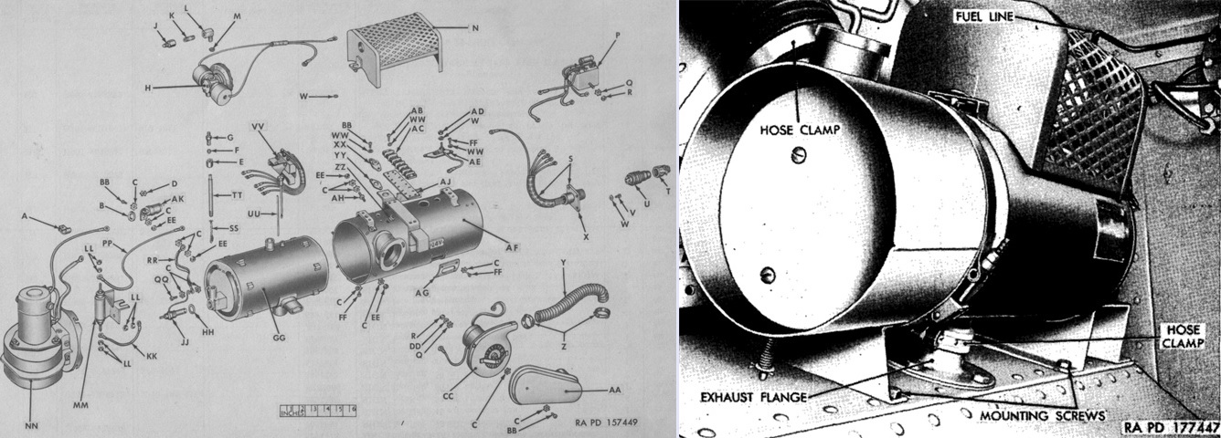
Early vehicles featured a gasoline-fueled 24-volt fuel-metering combustion-type personnel heater that was fed from the vehicle fuel tanks. It provided heat to the personnel compartment directly and to the driver's compartment via a flexible hose. It had a capacity of 20,000 Btu/hour, and was mounted in the sponson between the right wall of the engine compartment and the right hull wall. The combustion air, ventilating air, and exhaust passages were sealed so that combustion products could not enter the ventilating air stream. It is seen above in an exploded diagram on the left and installed on the right. The legend for the left image is: A. Clamp. B. Insulator. C. Washer. D. Washer. E. Nut. F. Sleeve. G. Union. H. Valve, assy. J. Connector. K. Nipple. L. Elbow. M. Screen. N. Guard. P. Relay. Q. Washer. R. Nut. S. Receptacle, assy. T. Connector. U. Plug. V. Bolt. W. Washer. X. Connector. Y. Hose. Z. Clamp. AA. Adapter. BB. Screw. CC. Blower, assy. DD. Washer. EE. Nut. FF. Screw. GG. Exchanger. HH. Gasket. JJ. Igniter. KK. Cable. LL. Nut. MM. Resistor. NN. Blower, assy. PP. Cable. QQ. Screw. RR. Strap. SS. Wick. TT. Standpipe. UU. Rod. VV. Switch. WW. Washer. XX. Flange. YY. Plate. ZZ. Grommet. AB. Bolt. AC. Block. AD. Nut. AE. Switch. AF. Case. AG. Plate. AH. Bolt AJ. Strip. AK. Capacitor. (Picture from ORD 9 SNL G-260 List of All Service Parts of Carrier, Personnel, Full-tracked, Armored, M75 and TM 9-755B Full-Track Armored Personnel Carrier T18E1.)
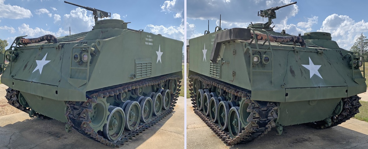
This is a later-production M75. The access door to the right of the engine, in the sloping plate just behind the engine exhaust pipe, is flat. On earlier vehicles an auxiliary generator was included, and its engine was installed under this access panel, giving it a humped cross section. The driver's hatch is visible on the vehicle's front left corner, with the commander's cupola behind and above. The large engine access door in the hull front is apparent, and its exhaust pipe is protected by an extension to the right headlight cluster brush guard. An extension to the exhaust pipe routes gases down to the side of the hull, which was doubtlessly appreciated by the commander when manning the cupola. The grille on the hull left side is for cooling air exhaust, and the small protuberance in front of this exhaust grille is for external activation of the vehicle's fire suppression system. This would have been found in an indentation on earlier machines. Similarly, the engine access door on the hull's right side is flat, in contrast to earlier vehicles.
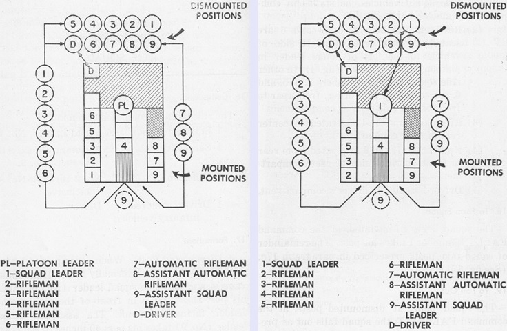
The dismounted and mounted positions for the rifle squad are drawn above. If the platoon leader or platoon sergeant was aboard, the left diagram was followed; otherwise, the troops were arranged as on the right. (Picture from FM 17-77 Crew Drill Armored Personnel Carrier, Full-track M75.)
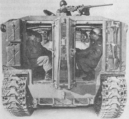
A rifle squad is mounted, although the center seat is obscured from view. (Picture from FM 17-77 Crew Drill Armored Personnel Carrier, Full-track M75.)
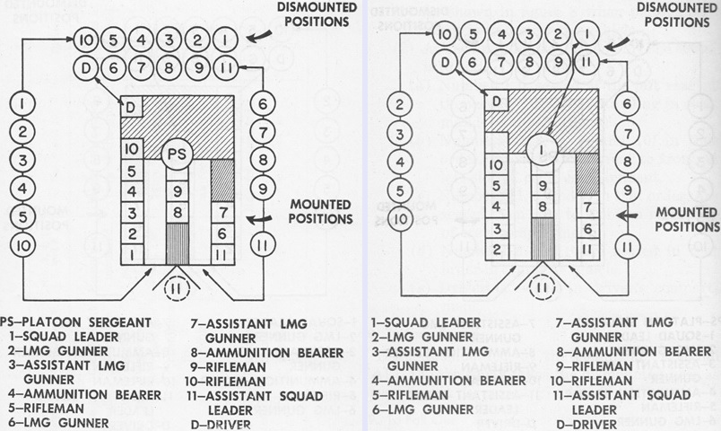
The mounted and dismounted posts for a light machine gun squad are similarly detailed. (Picture from FM 17-77 Crew Drill Armored Personnel Carrier, Full-track M75.)
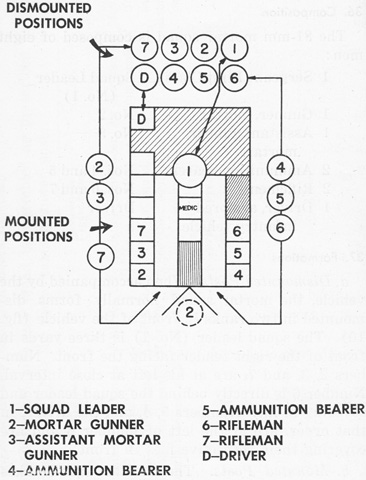
When the vehicle was used to transport an 81mm mortar and its squad, the above seating plan was followed. (Picture from FM 17-77 Crew Drill Armored Personnel Carrier, Full-track M75.)
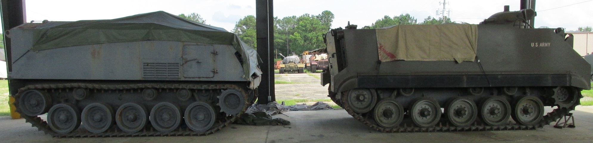
An interesting comparison between the outgoing M75 and its replacement can be made here. Note the different side access hatch compared to the early machines, and the absence of shock absorbers on wheels two and four.
