8" Howitzer Motor Carriage M43.
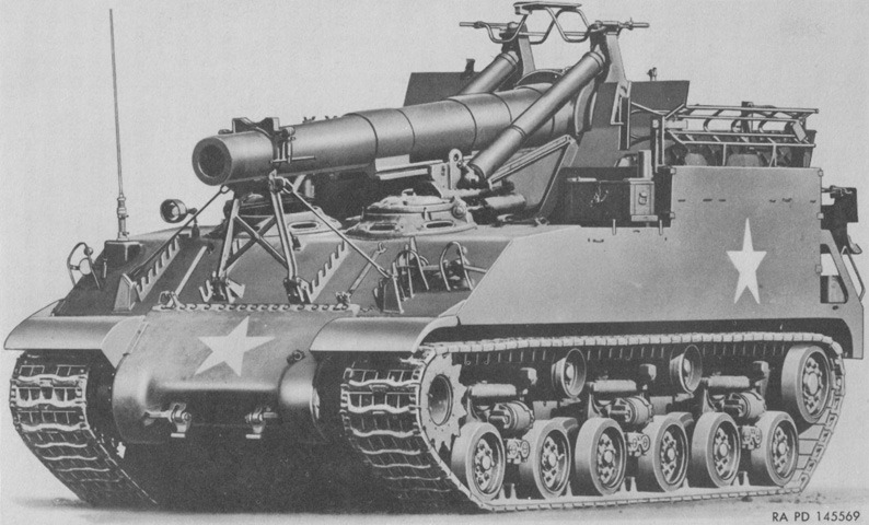
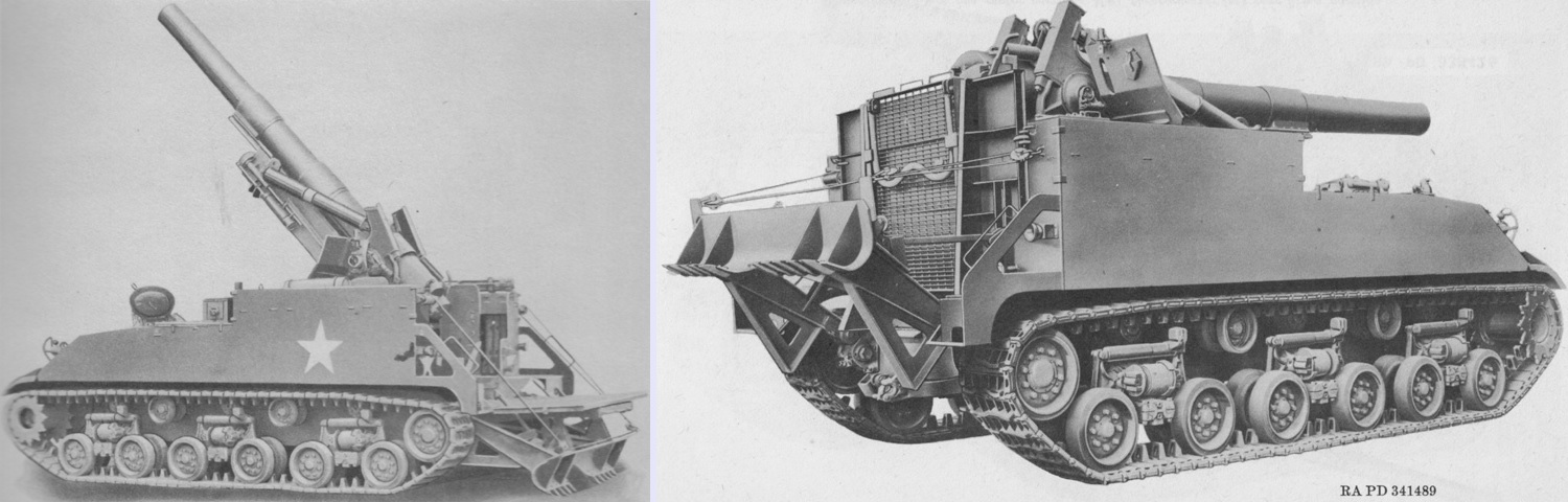
The shorter length of the 8" howitzer M1 or M2 is immediately apparent when it is compared with the 155mm gun M1A1 or M2 found on the 155mm GMC M40. The drivers' cupolas are visible from this angle, along with the spare track stowage on the upper front hull. A loading tray M2 is stowed on top of the howitzer mount, and a loading ramp is kept above the left wall of the fighting compartment. (Picture from TM 9-3054.)
Seen from the opposite angle, the brush guards for the missing headlights and siren and the shield for the crew beside the howitzer mount are visible. The upper half collar for the howitzer travel lock is not present.
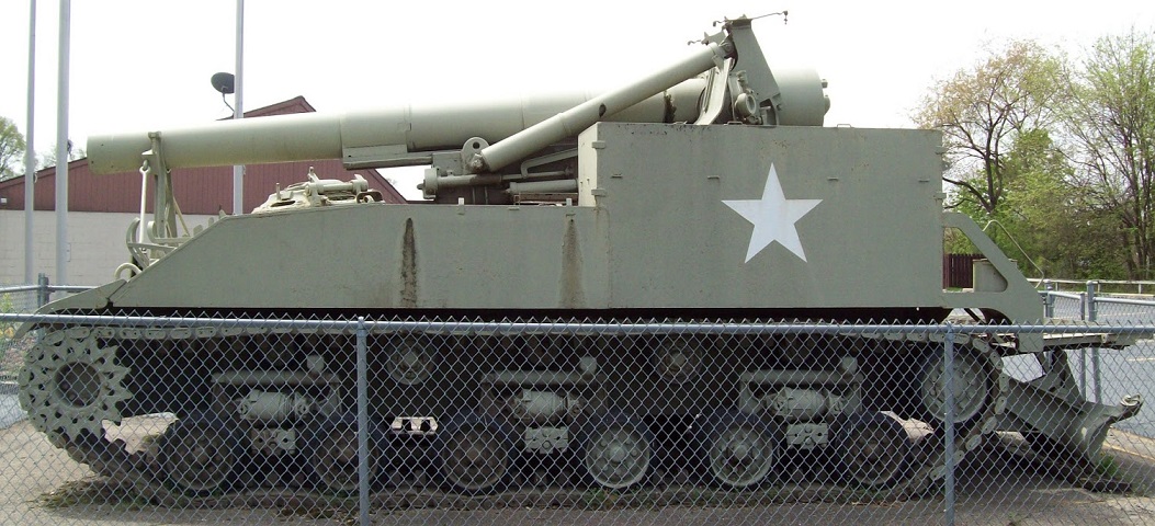
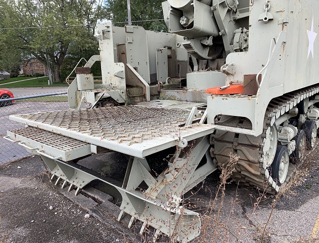
The rear platform is lowered, giving the howitzer crew extended working room when servicing the piece. (Picture courtesy Tank and AFV News.)
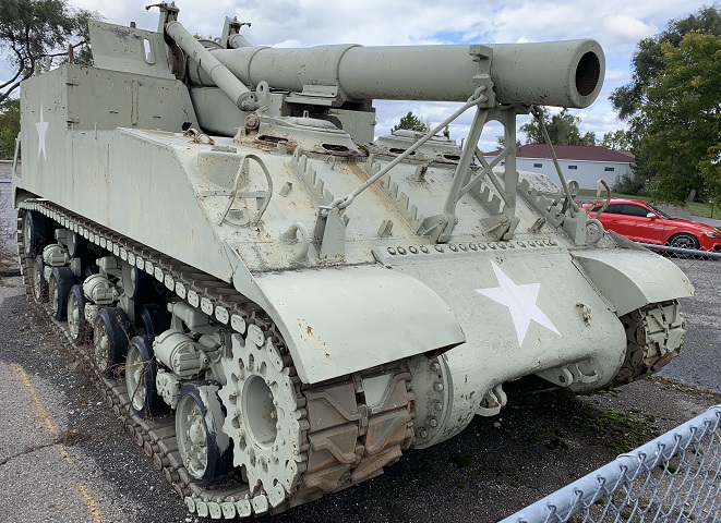
A view of the hull front gives further details of the drivers' cupolas and the racks on the hull front intended to store extra track blocks. The cupolas were fixed, but the doors with the periscope mounts could be rotated. The top of the howitzer travel lock is missing from this machine, but if present we would see that it was indented on both sides with different sized radii so that it could accommodate both the 8" howitzer and the 155mm gun simply by being reversed.
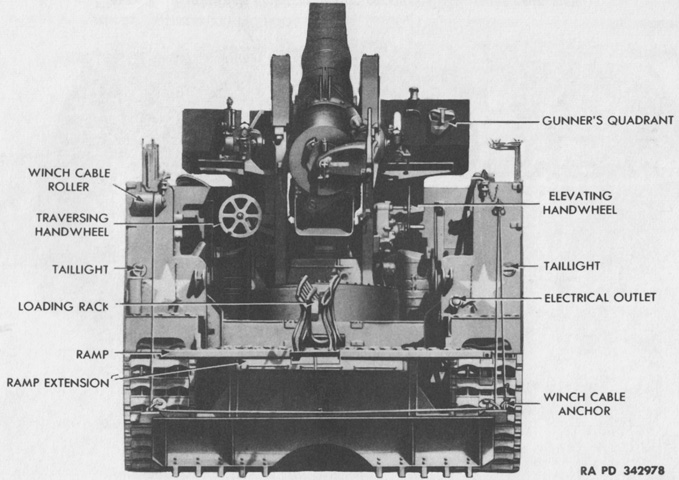
The rear of the vehicle is labeled in this image. (Picture from TM 9-747 Sep 1947.)
On the left, the spade and platform are lowered, the howitzer is elevated for firing, and the driver's cupola door is open. The platform and spade are stowed for travel on the right. (Picture from TM 9-3054 and TM 9-1747.)
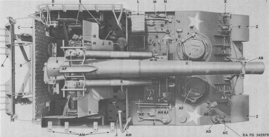
The top of the vehicle is shown here. A. Spade. B. Ramp extension. C. Ramp. D. Loading rack. E. Crew seat. F. Loading tray. G. Panoramic telescope M12. H. Telescope mount M18A1. J. Universal shell rack. K. Carburetor air cleaners. L. Recoil pump. M. Mattock. N. Ax. P. Left fuel tank filler cover. Q. Track adjusting wrench. R. Crowbar. S. Engine oil tank filler cap cover. T. Shovel. U. Fixed fire extinguisher dual pull cable exterior shield. V. Driver's cupola doors. W. Driver's direct vision blocks. X. Blackout driving light. Y. Klaxon. Z. Front fender. AA. Track link rack. AB. Traveling lock. AC. Headlight. AD. Antenna. AE. Searchlight. AF. Assistant driver's cupola door. AG. Starting crank. AH. Mattock handle. AJ. Sledge hammer. AK. Right fuel tank filler cover. AL. Engine compartment cover grille. AM. Lifting hook boom. AN. Cal. .30 carbine mounting brackets. AP. 8 in. howitzer. (Picture from TM 9-747 Sep 1947.)
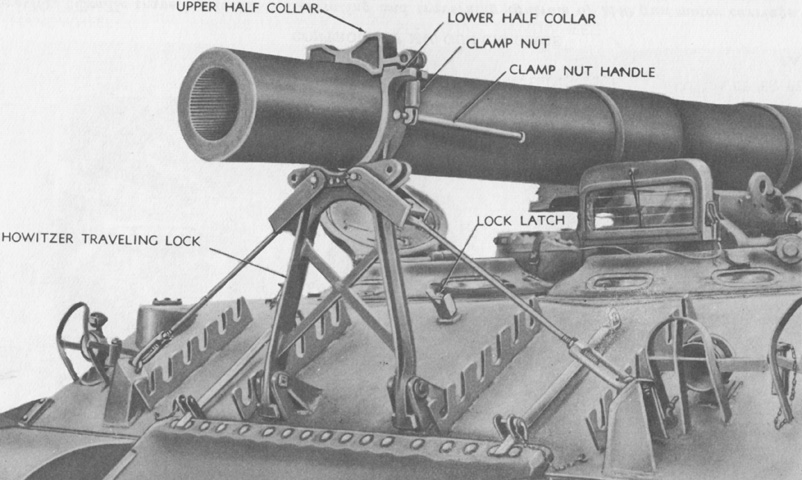
The complete travel lock is shown here. Note that the upper half collar is reversible for the 155mm ordnance on the M40. (Picture from TM 9-747 Sep 1947.)
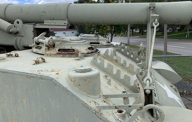
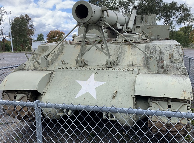
The assistant driver's cupola door is pointed to the right rear, while the driver's faces more to the front. An antenna mount is welded behind the right-side headlight cluster, and a shaft for mounting a spotlight can be seen next to the assistant driver's cupola. Clips for stowing a tow cable are attached to the hull roof, hull front, and final drive and differential cover. An exploded view of the cupola assembly is at the right. A. Hinge tube. B. Azimuth scale. C. Cupola race lock knob. D. Periscope recess filler. E. Latching handle. F. Azimuth scale pointer. G. Cupola door race plate. H. Cupola door race ring. I. Torsion springs. J. Retainer cap. K. Prism wedge. L. Direct vision prism. M. Cupola body. N. Prism bezel. O. Hold open lock. (Right image from TM 9-1747.)
Outboard of and behind the driver's cupola on the hull roof is the guard that housed the external fire extinguisher handles, and another tow cable clip can be seen in front of the fire extinguisher handle guard.
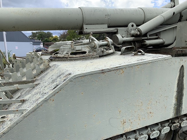
Details of the howitzer mount can be seen in this view, along with a fuel filler cap in the hull roof behind the driver.
Another angle of the howitzer mount and left-side shield for the crew is provided here.
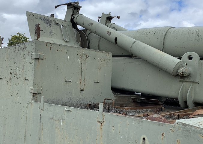
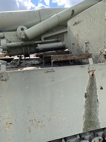
A similar view of the right side of the mount is shown in this picture.
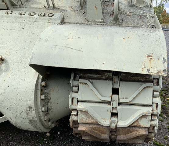
The wider hull compared to the tank from which it was automotively derived forced the use of longer connections for the final drives.
Casting adapters were welded to the wider hull sides in order to mesh them with the final drive and differential housing. The bolts on these extensions were angled forward to make up for the steeper slope of the propeller shaft necessitated by moving the engine forward.
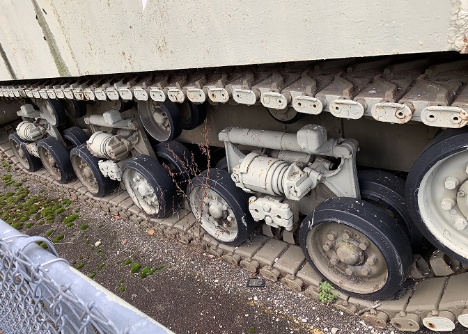
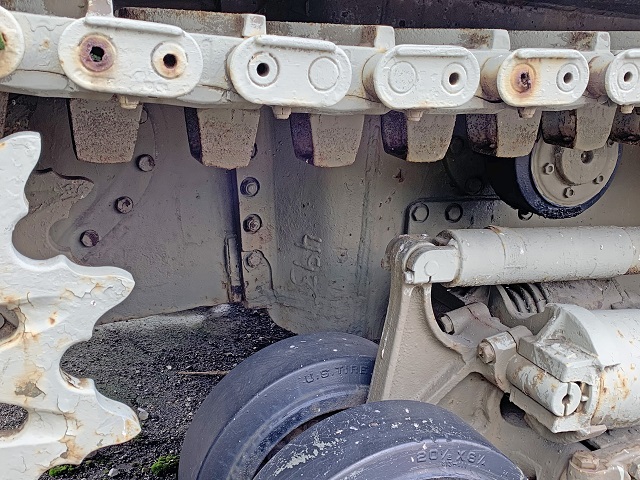
The longer hull also saw increased spacing between the suspension bogies versus the tank.
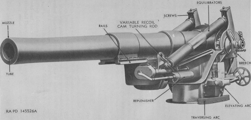
The howitzer mount is isolated from the motor carriage in this image. (Picture from TM 9-3054.)
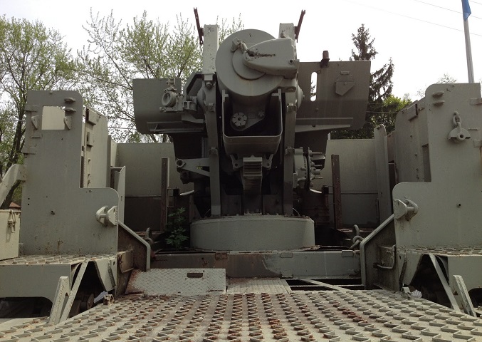
The rear platform is lowered, allowing an overall look at the fighting compartment. (Picture courtesy Tank and AFV News.)
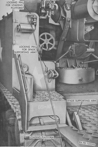
The machine above is missing the locking pins for the loading platform and spade supporting arm, as well as the roller for the winch cable. (Picture from TM 9-3054.)
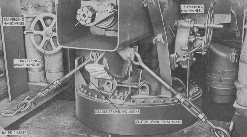
The howitzer cradle was provided with a traveling lock in addition to that found on the howitzer tube. The clutch lever pedal hook allowed the crew to release the brake which locked the elevating mechanism. Ammunition racks can be seen at the front corners of the fighting compartment, and the right-side engine air cleaner is visible ahead of the elevating handwheel. (Picture from TM 9-3054.)
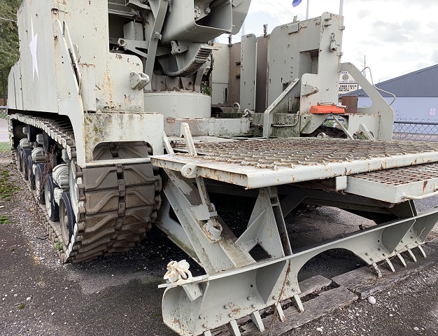
Underfloor stowage can be seen as well as the howitzer's elevation arc and shielding for the crew near the howitzer tube. A longer grated platform was able to be pulled out from under the solid platform to provide more working space for the howitzer crew. Details of the stabilization spade, including a pulley to assist in its retraction, can be discerned.
Stowage in the left side of the fighting compartment can be seen here.
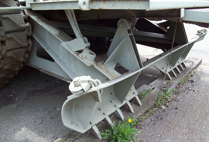
The reinforcing members of the spade and the rollers that run along the bottom of the crew's platform are highlighted in this image. (Picture courtesy Tank and AFV News.)
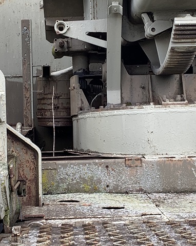
Air cleaners for the radial engine were mounted at the front of the fighting compartment to either side of the ordnance mount.
Vertical ammunition racks that could stow either 155mm or 8" rounds were installed in the floor in the front corners of the fighting compartment.
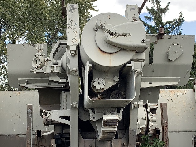
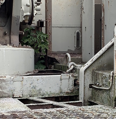
The demilitarized howitzer breech is evident in this view, along with the sight mount on the left of the howitzer mount and the traversing handwheel mount below this. The elevation handwheel would be attached to the mount on the opposite side of the traversing handwheel.
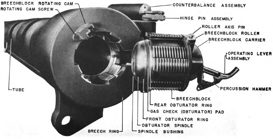
The open breech for the howitzer M1 is illustrated here. The complete howitzer weighed 10,240lb (4,645kg), the tube was 202.5" (514.4cm) long, and the howitzer could fire a high-explosive shell to 18,510 yards (16,930m). (Picture from TM 9-747 Feb 1945.)
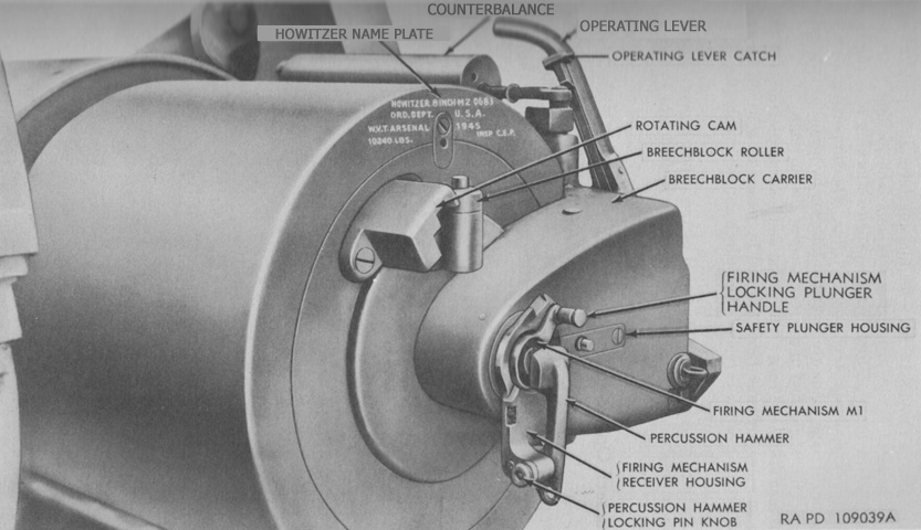
The breech controls are labeled in this image. To open the breech, the firing mechanism was first removed. Then the operating lever catch was depressed to unlock the breechblock, and the operating lever was pulled to the rear until the breech thread sectors were clear. The handle could then be pulled to the right until the spring counterbalance held the breech mechanism open. The breech was not to be opened if the howitzer was elevated more than 240 mils due to the possibility of the breechblock swinging open too quickly. (Picture from TM 9-3054.)
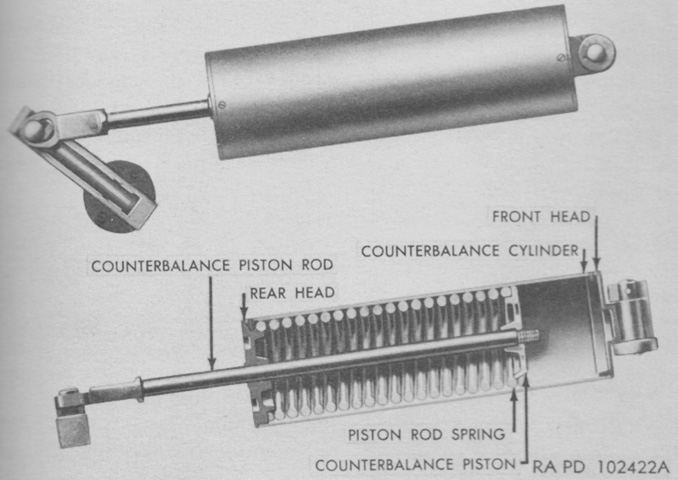
The breech counterbalance assisted in swinging the breech carrier when closing the breech and resisted the opening movement until it was almost completed. As the breech would approach fully open, the counterbalance arm and hinge pin arm would pass dead center, and the spring tension would then help in holding the breech open. (Picture from TM 9-3054.)
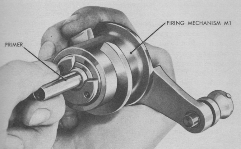
To fire the howitzer, a primer was inserted into the firing mechanism M1, then the firing mechanism was screwed into the breech. A belt was provided with pouches to hold the primers used with the mechanism. (Picture from TM 9-3054.)
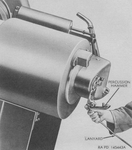
When the lanyard was attached to the percussion hammer and then sharply pulled, the hammer would strike the firing pin, setting off the primer and igniting the propelling charge. A safety rim welded around the firing mechanism housing prevented the percussion hammer from striking the firing pin unless the firing mechanism was fully inserted. (Picture from TM 9-3054.)
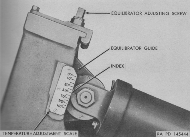
Pneumatic equilibrators filled with pressurized nitrogen gas were used to help balance the weight of the howitzer's muzzle end and reduce the effort required to elevate the ordnance through low elevations. As the howitzer was depressed, a plunger in each cylinder was drawn forward, further compressing the nitrogen. A scale was used to ensure the gas in the equilibrators was at the proper pressure depending on the atmospheric temperature, and a screw was used to adjust the equilibrator to the proper angle and length. If the temperature was below 0°F (-18°C) or above 110°F (43°C), nitrogen would have to be added or removed from the equilibrators, respectively, to achieve appropriate handwheel loading. (Picture from TM 9-3054.)
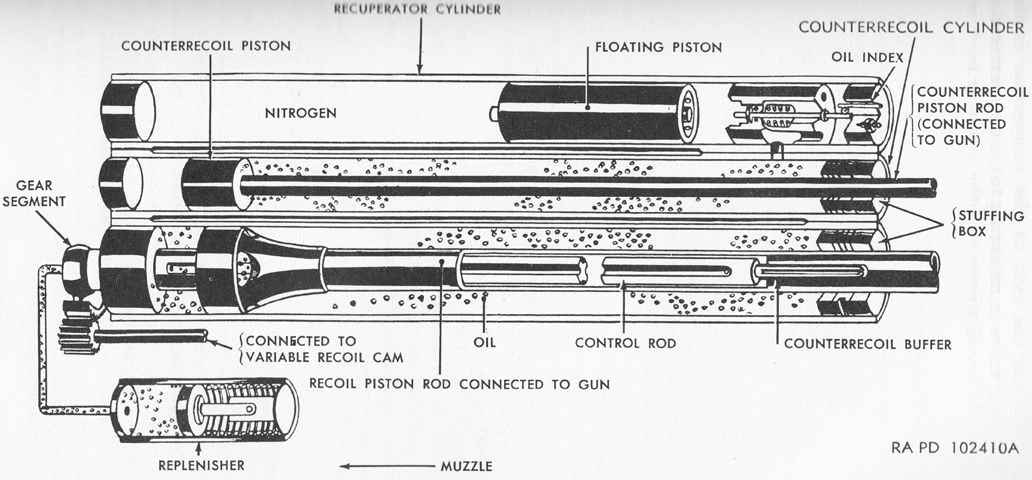
The recoil mechanism M23, M23A1, or M23A2 could be found on the M43. The M23A1 was an M23 modified to add a spacer to the floating piston, as well as use new low-temperature packing fillers and new oil and grease. The M23A2 was a newly-manufactured M23 with a single-piece floating piston instead of one with a spacer.
The mechanism was a variable recoil hydropneumatic type. The recoil and counterrecoil piston rods were secured to the breech end of the howitzer and therefore moved with it. During recoil, oil in the recoil cylinder was forced through openings past the recoil piston, absorbing energy and arresting the howitzer's rearward motion. The recoil control rod inside the recoil piston rod remained stationary during recoil, and rotation of the control rod controlled the size of the groove openings through which the oil flowed past the piston. A gear on the forward end of the control rod engaged the cam gear segment of the variable recoil mechanism, so that the control rod rotated as the howitzer elevation changed. Elevating the howitzer reduced the length and size of the grooves, and therefore shortened the recoil length.
Counterrecoil was controlled by the recuperator and counterrecoil cylinders, which were connected near their rear ends. The recuperator had a valve near this connection that closed during counterrecoil. During recoil, the counterrecoil piston was forced to the rear, which pushed oil out of the counterrecoil cylinder into the recuperator through the open valve. The floating piston in the recuperator was pushed forward by the oil, compressing nitrogen in the cylinder ahead of it. The compressed nitrogen would expand during counterrecoil, pushing the floating piston to the rear which throttled the oil back into the counterrecoil cylinder through the recuperator valve and pushed the counterrecoil cylinder forward again, returning the ordnance to battery. The rear of the control rod acted as a buffer during counterrecoil, throttling a small amount of the recoil oil through grooves into the recoil cylinder and slowing the counterrecoil motion to avoid a shocking force. (Picture from TM 9-3054.)
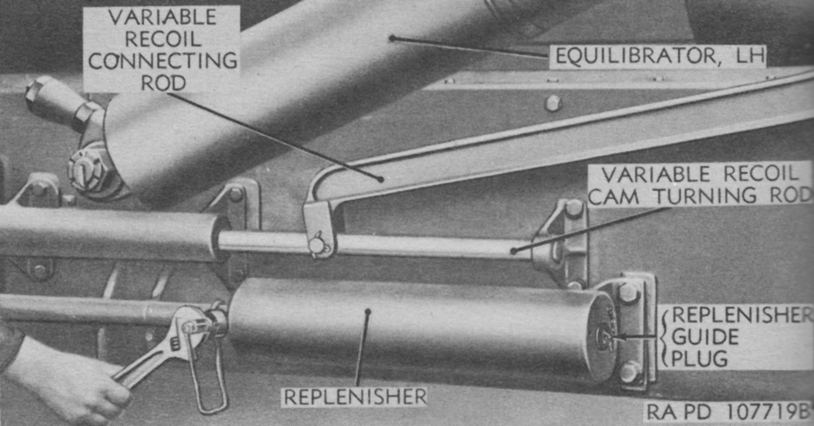
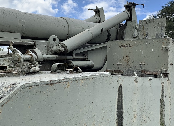
The replenisher acted as a reservoir for extra recoil oil when heat from the atmospheric temperature or from firing the ordnance expanded the oil. Similarly, when cold temperatures caused the oil to contract, oil from the replenisher would flow into the recoil cylinder. The attachment of the variable recoil rods on the side of the howitzer mount can also be seen. The variable recoil cam was linked to the howitzer top carriage by the variable recoil connecting rod, which moved forward or backward as the howitzer was elevated, turning the variable recoil cam, which turned the control rod in the recoil cylinder and thereby adjusted recoil length. (Picture from TM 9-3054.)
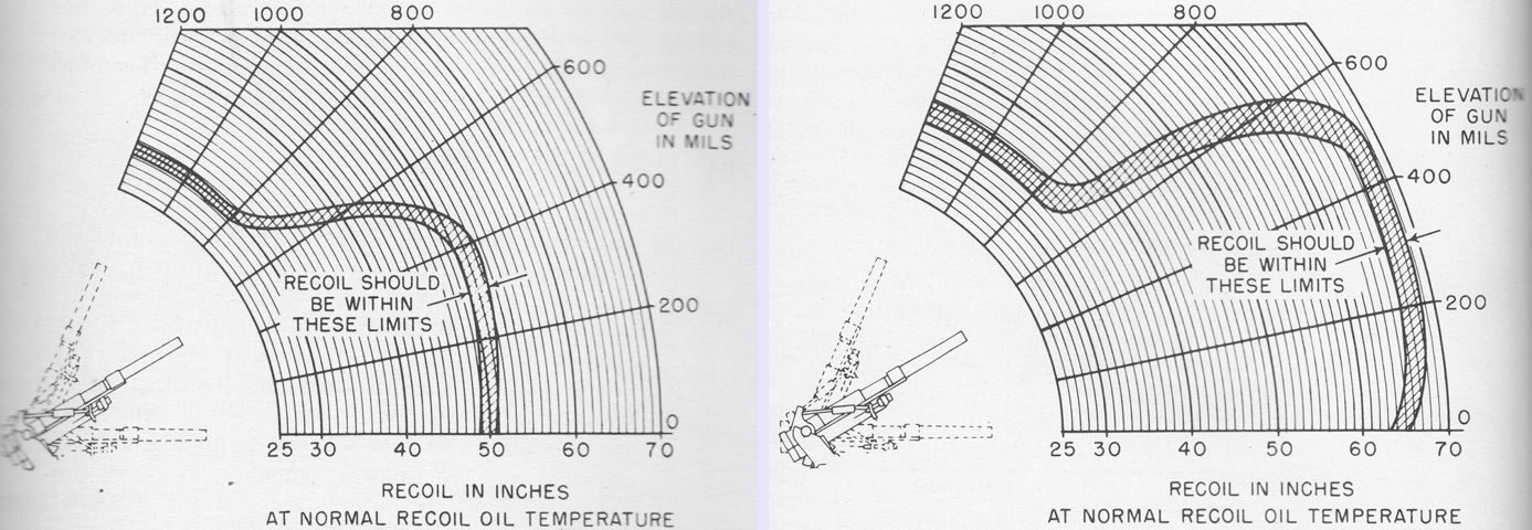
The allowable recoil limits are shown here for normal charge (1,380 ft/s [421m/s]) on the left and supercharge (1,950 ft/s [594m/s]) on the right when the recoil oil was at a normal temperature of 70°F (21°C). For the first few rounds fired and during abnormal temperatures, the recoil might not match the limits shown. (Picture from TM 9-3054.)
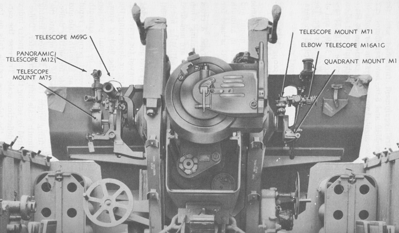
The mounted sighting devices are detailed in this picture. (Picture from TM 9-747 Sep 1947.)
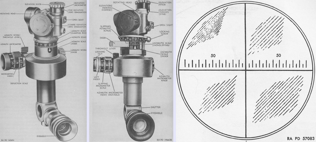
Used for indirect firing or for direct firing in emergency cases if the telescope M69G and/or elbow telescope M16A1G were broken, the 4x panoramic telescope M12 seen on the left had a 10° field of view. The eyepiece was offset 45° so the user could be clear of the ordnance. The M12A7C shown in the center was improved by the addition of a slipping azimuth scale and locking screw; a nonslipping azimuth scale that turned with the rotating head; a door that permitted reading of the nonslipping azimuth scale; a slipping azimuth micrometer scale and locking nut; and a nonslipping left index that moved by turning the azimuth micrometer knob. The reticle pattern is drawn on the right. The horizontal crossline was divided into 5-mil intervals numbered every 50 mils. (Picture from TM 9-3054.)
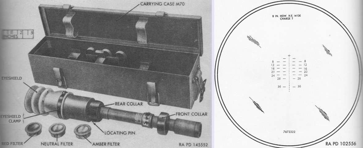
The 3x telescope M69G was used for direct fire and had a 10°24' field of view. Its reticle pattern, calibrated for the 8" high-explosive shell M106 fired at charge 7, is sketched on the right. The cross represented zero range and deflection and was used for boresighting. Each part of the broken vertical line represented 100 yards (91m) range, and was numbered every 400 yards (360m) up to 2,800 yards (2,560m), then the numbering jumped to 3,600 yards (3,290m). The bottom of the vertical line represented 4,100 yards (3,750m). Each horizontal line and space denoted a deflection of 5 mils. (Picture from TM 9-3054.)

Direct fire was typically a two-man operation, with the gunner traversing the mount using the telescope M69G and the number 1 man of the gun crew elevating the mount with the elbow telescope M16A1G. The 3x M16A1G had a 13° field of view and used a reticle similar to that of the telescope M69G. (Picture from TM 9-3054 and TM 9-2300 Artillery Matériel and Associated Equipment.)
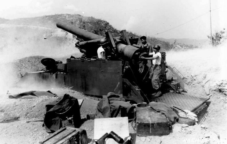
The size of the vehicle and the working space provided by the folding platform can be seen in this image where the crew is present. (Picture taken 13 Aug 1952 by Kelemanik; available from the U.S. Army Center of Military History.)
