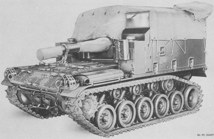
155mm Self-propelled Howitzer M44.
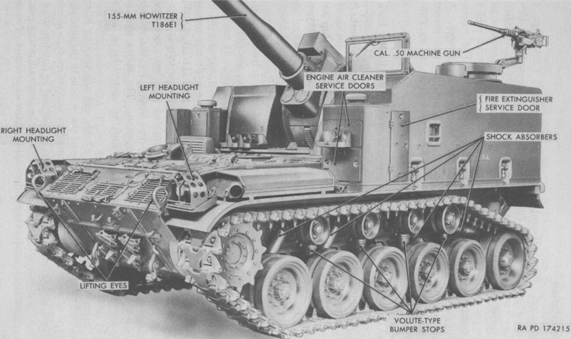
The general layout of the M44 can be seen here, with the open-topped superstructure to the rear and drivetrain to the front. There are three cab-to-hull side clamps running down each side of the vehicle, and the rear idler wheel and rear return roller are larger than the other road wheels and return rollers, respectively. While the early vehicle above includes a shock absorber on the trailing idler wheel, this feature would be deleted for production machines. (Picture from TM 9-7004 Self-propelled 155-mm Howitzer T194.)
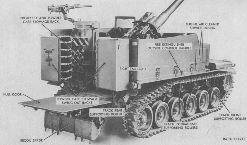
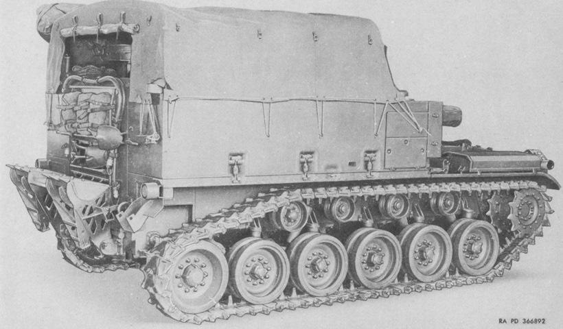
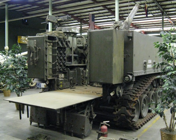
The open-topped nature of the fighting compartment can be seen from this angle. The recoil spade is lowered, and the rear hull door is hinged downward to provide working space for the howitzer crew. (Picture from TM 9-7004 Self-propelled 155-mm Howitzer T194.)
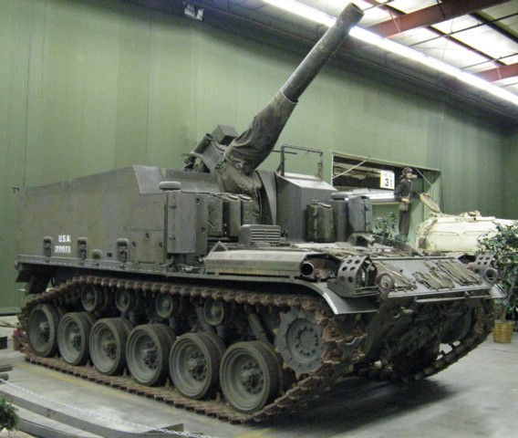
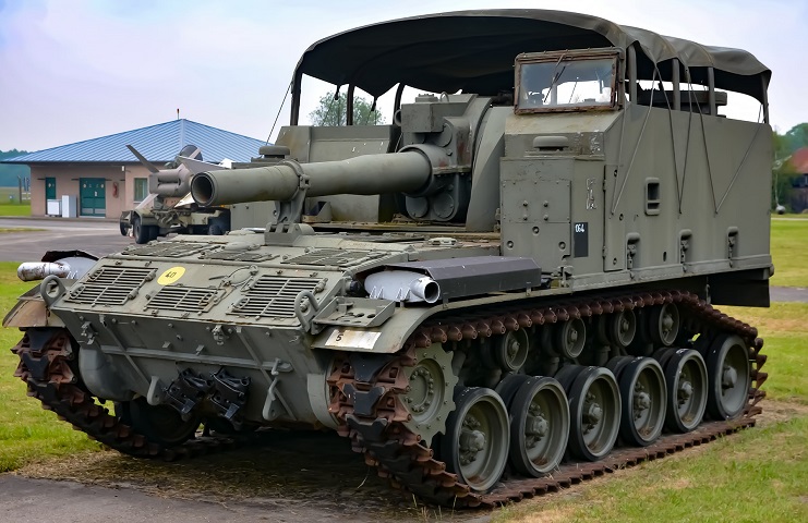
The howitzer on this vehicle has its canvas covers fitted, and the external fire extinguisher activation handle is between the front two cab-to-hull clamps on this side. The cylindrical telescope M93 can be seen on the howitzer mount's right side.
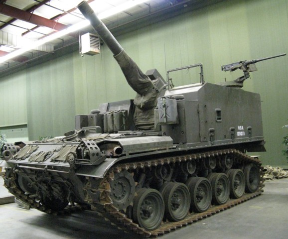
The ring mount for the .50cal machine gun is on the vehicle's left side, and the driver's windscreen is mounted on the cab's front left side.
With the crew exposed to the elements due to the open fighting compartment, weather protection was provided in the form of canvas covers. The machine gun was protected as well. (Picture from ORD 9 SNL G-279.)
This machine has the bows and top cover mounted, although this setup does not provide complete coverage from the weather. (Picture courtesy Gijs Boerendans.)
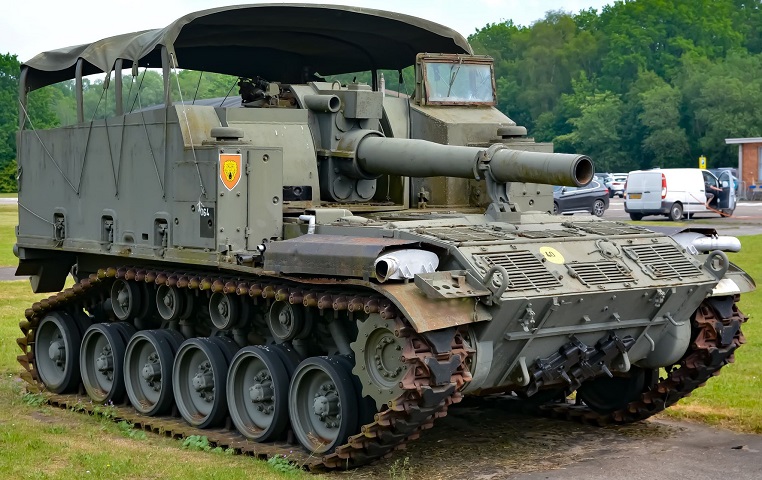
The air intake grilles are uncovered on this vehicle, and the howitzer is secured in its travel lock. The driver's windshield is mounted. (Picture courtesy Gijs Boerendans.)
The spade and door are secured on this machine, revealing stowage for pioneer tools. (Picture from ORD 9 SNL G-279.)
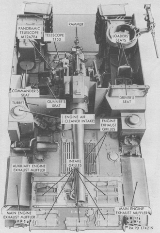
This early vehicle provided seating for five crewmembers. The driver was at the front left of the fighting compartment, with the machine gun mount and seats for two loaders to his rear. The gunner sat in the howitzer turret, and the commander was at the right rear corner. (Picture from TM 9-7004 Self-propelled 155-mm Howitzer T194.)
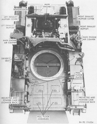
The hull is seen from above with the turret, engine decking, and cab removed. The driver's station is visible on the left, and the opening in the fighting compartment floor for the turret is obvious. A torsion bar cover can be seen through the opening for the turret. (Picture from TM 9-7004 Self-propelled 155-mm Howitzer T194.)
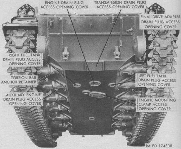
The underside of the hull is seen from the front, with various plugs and covers labeled. (Picture from TM 9-7004 Self-propelled 155-mm Howitzer T194.)
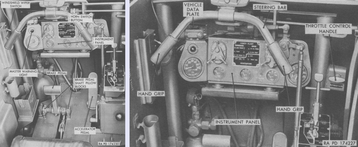
The driver controlled the vehicle with a steering bar. Pulling the left hand grip would cause a left turn or pivot, and vice-versa for the right hand grip. The steering bar would return to the neutral position when released. When reversing, the rear of the vehicle would turn in the opposite direction; i.e., the rear of the machine would swing to the right when the left hand grip was pulled. (Picture from TM 9-7004 Self-propelled 155-mm Howitzer T194.)
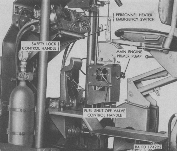
The driver's position is seen from below with the cab removed. The vehicle was equipped for the installation of two personnel heaters, and if these were present the emergency switch could be moved to the ON position to stop their operation. One of the fixed fire extinguisher bottles is seen at the left. (Picture from TM 9-7004 Self-propelled 155-mm Howitzer T194.)
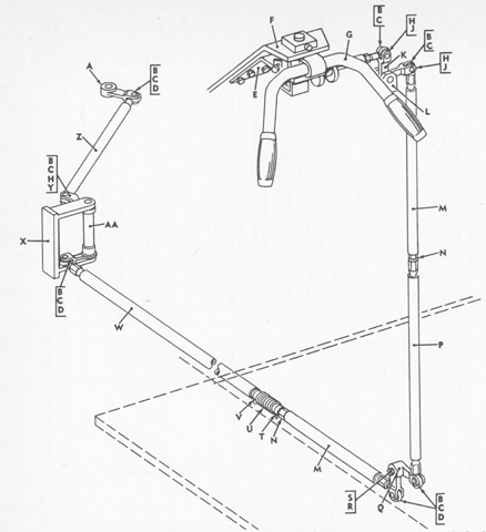
The driver's steering bar differed from that found in the 76mm gun tank M41. (Picture from ORD 9 SNL G-279.)
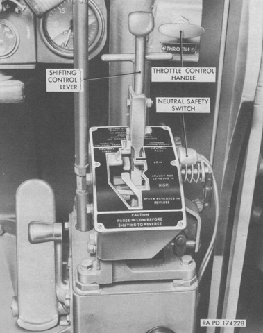
The shifting control lever had five positions: NEUTRAL PARK, NEUTRAL STEER, LOW, HIGH, and REVERSE. The safety lock control handle in front of the shifting control lever needed to be pulled upwards to shift from NEUTRAL PARK to NEUTRAL STEER or into REVERSE. LOW was used for normal driving on hard-surfaced roads, ascending or descending steep grades, or soft or rough terrain. HIGH was used when the vehicle exceeded 6-10mph (10-16kph). The parking brake lock was set by pressing the brake pedal and then placing the shifting control lever in NEUTRAL PARK, while using the steering bar with the lever in NEUTRAL STEER would pivot the vehicle in place. (Picture from TM 9-7004 Self-propelled 155-mm Howitzer T194.)
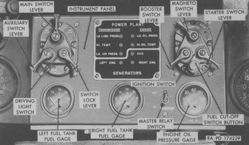
The driver's instrument panel is labeled. The left column of warning lights in the center signified, from top to bottom, transmission oil pressure falling below 11psi (.77kg/cm²); transmission oil temperature climbing above 280°F (140°C); the LO. AIR PRESS. light was not used; and that the main engine generator was inoperative. The right column of warning lights indicated, top to bottom, main engine oil pressure dropping below 11psi (.77kg/cm²); main engine oil temperature above 200°F (93°C); the auxiliary generator and engine either not running, the auxiliary generator not charging while the auxiliary engine was running, or that the auxiliary engine pressure was low. The RIGHT ENG. light was also not used. (Picture from TM 9-7004 Self-propelled 155-mm Howitzer T194.)
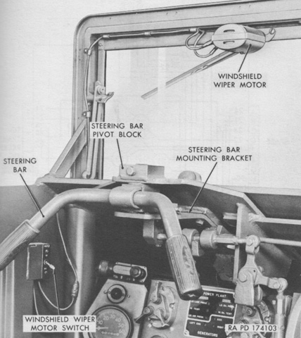
The driver's removable windshield included an electric wiper. (Picture from TM 9-7004 Self-propelled 155-mm Howitzer T194.)
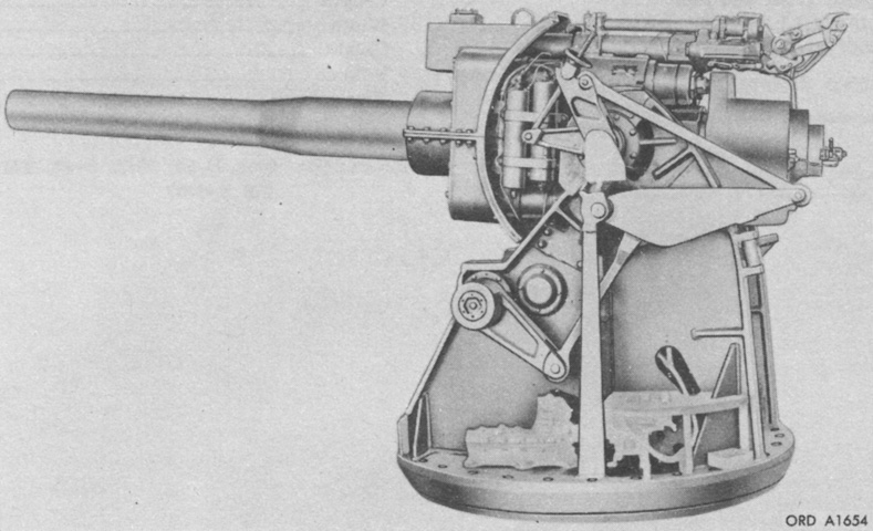
The howitzer mount M80 is isolated in this image. It weighed 10,940lb (4,962kg). (Picture from TM 9-500 C3 Data Sheets for Ordnance Type Materiel.)

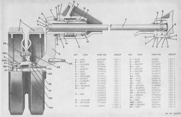
A rear view of the turret and howitzer mount is shown here. The letters refer to a list of part numbers. (Picture from ORD 9 SNL G-279.)
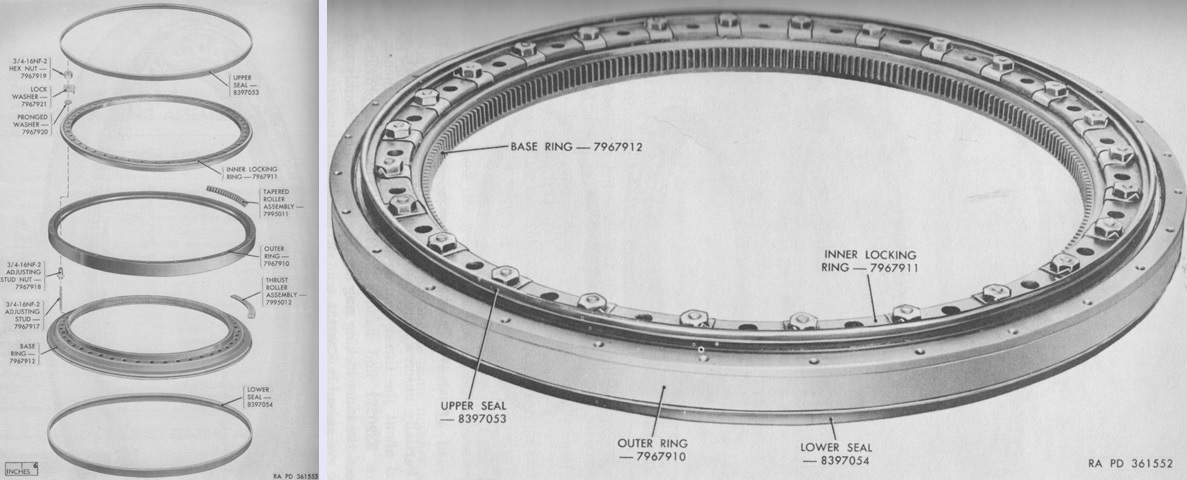
Exploded and assembled views of the turret bearing assembly are provided above. Manufactured by the Kaydon Engineering Company from Muskegon, Michigan, its inner and outer diameters were 50.8000" and 65.2500" (129.032cm and 165.735cm), respectively, and it weighed 1,442lb (654.1kg). The base ring was bolted to the vehicle hull, and the turret assembly was bolted to the outer ring. The inner edge had 256 teeth, while the eight thrust roller assemblies were composed of a retainer and 20 rollers, and the eight tapered roller assemblies were made of a retainer and 18 rollers. (Picture from TM 9-7005.)
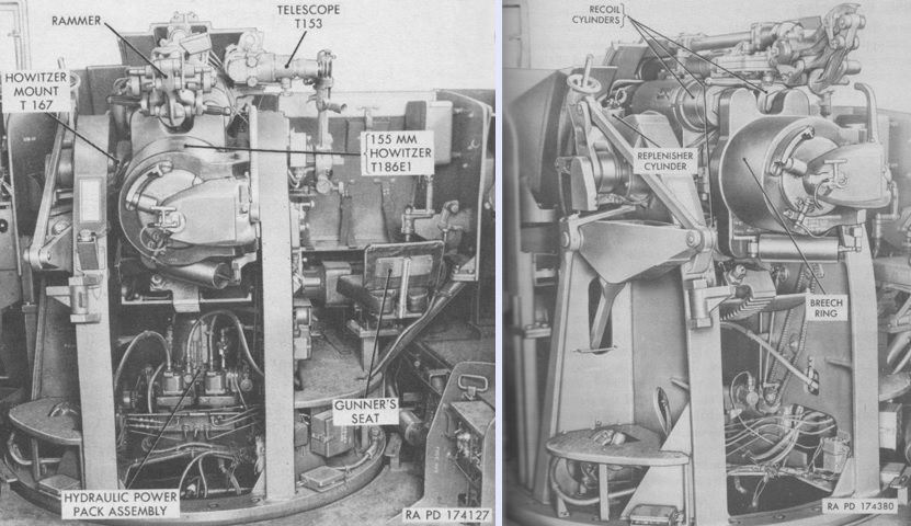
Two views of the turret installed in the hull are provided. The 155mm howitzer T186E1 was standardized as the M45, the howitzer mount T167 as the M80, and the telescope T153 as the M93. (Picture from TM 9-7004 Self-propelled 155-mm Howitzer T194.)
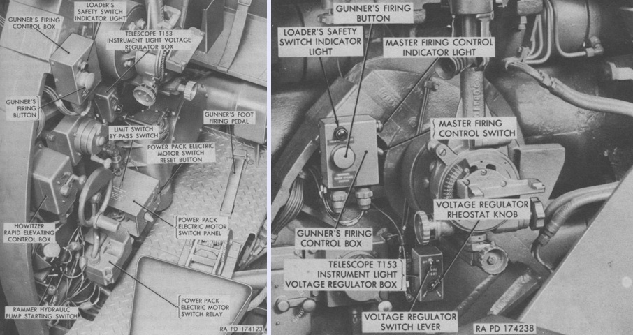
An overview of the gunner's position in the turret is on the left, while a more detailed look at his firing control box is on the right. (Picture from TM 9-7004 Self-propelled 155-mm Howitzer T194.)
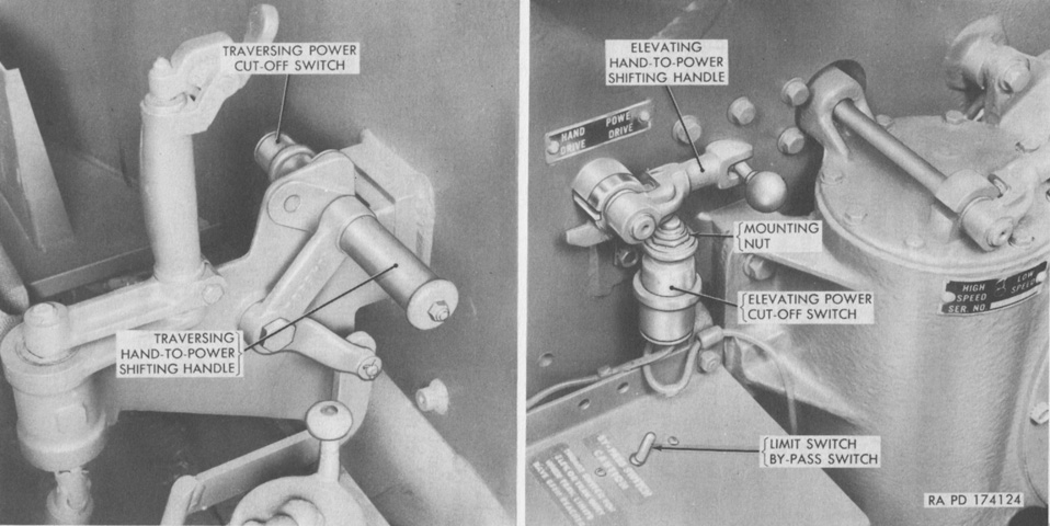
The hand-to-power shifting handles were used by the gunner to change between power and manual traverse and elevation. The traversing hand-to-power shifting handle was on the right turret wall, and was set for power operation when it was pushed away from the gunner. The elevation hand-to-power shifting handle was to the gunner's left, and was also set for power operation when pointed away from the gunner. The handles activated or deactivated power cutoff switches and also disengaged the manual control handles from their gearing. (Picture from TM 9-7004 Self-propelled 155-mm Howitzer T194.)
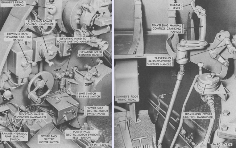
The gunner's elevation and traverse controls are labeled in this image. The rapid elevating control handle quickly elevated the howitzer when moved upwards and depressed the howitzer when moved downwards. The elevating speed control handle allowed the gunner to change between high and low elevating speeds. Power elevation was only to be used in low speed, while manual could be used in either high or low. (Picture from TM 9-7004 Self-propelled 155-mm Howitzer T194.)
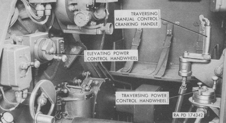
A further view of the gunner's controls is provided here. (Picture from TM 9-7004 Self-propelled 155-mm Howitzer T194.)
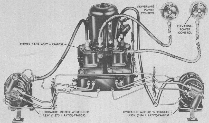
The components of the turret traversing and howitzer elevating system are labeled here. (Picture from TM 9-7205-2.)
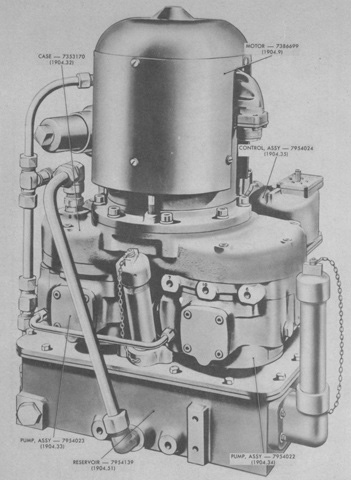
The isolated elevation and traversing powerpack is seen from the front. (Picture from ORD 9 SNL G-279.)
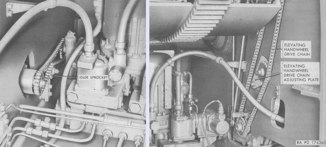
Manual turret traverse and howitzer elevation were accomplished by chains. The traversing drive chains and sprockets are on the left, and the elevating drive chain is seen on the right. (Picture from TM 9-7004 Self-propelled 155-mm Howitzer T194.)
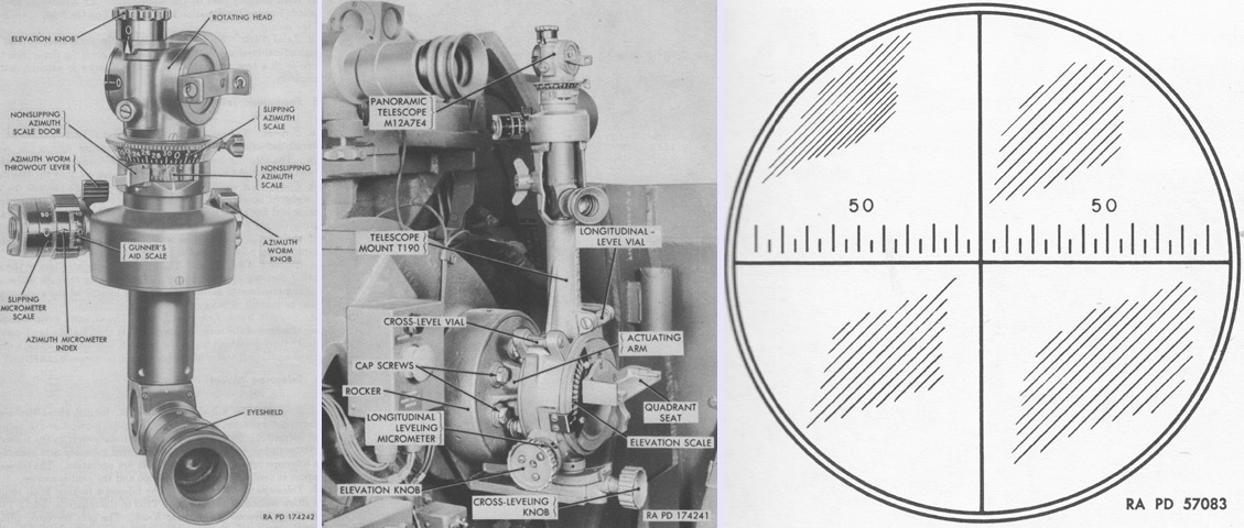
The panoramic telescope M12A7K was normally used to lay the howitzer in azimuth during indirect fire, although it could be used for direct fire in emergencies. It was a 4x device with a 10° field of view. It is seen isolated on the left and installed in its mount in the center. Its reticle pattern is sketched on the right, and consisted of 5-mil graduations out to 90 mils on each side of the center line. (Picture from TM 9-7004 Self-propelled 155-mm Howitzer T194.)
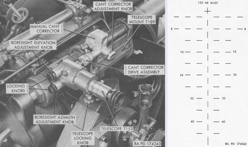
The telescope M93 was used to sight the howitzer during direct fire, and also had 4x magnification and a 10° field of view. Its reticle pattern is drawn on the right. The range lines were numbered in hundreds of yards, and each horizontal space and line represented a deflection of 5 mils. (Picture from TM 9-7004 Self-propelled 155-mm Howitzer T194.)
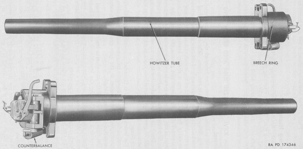
The 155mm howitzer M45 weighed 2,970lb (1,350kg) complete, with the tube itself making up 2,140lb (971kg) of that total. It was 156.62" (397.81cm) long overall, with a bore length of 141.8" (360.2cm), or 23 calibers. Its chamber capacity was 795in³ (13.0L) and maximum powder pressure was 32,000psi (2,250kg/cm²). It could fire a 95lb (43kg) high-explosive shell M107 to a range of 16,355 yards (14,955m) using a charge M4A1. (Picture from TM 9-7004 Self-propelled 155-mm Howitzer T194.)
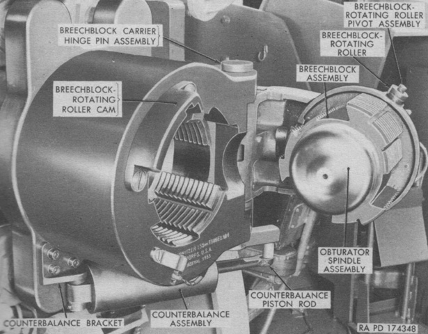
The howitzer breech was an interrupted stepped thread type that swung horizontally. It was opened and closed manually using an operating lever on the right side. The counterbalance assembly contained a strong compression spring that assisted closing the breech when the howitzer was elevated, as well as tending to hold the breech in the fully open position. (Picture from TM 9-7004 Self-propelled 155-mm Howitzer T194.)
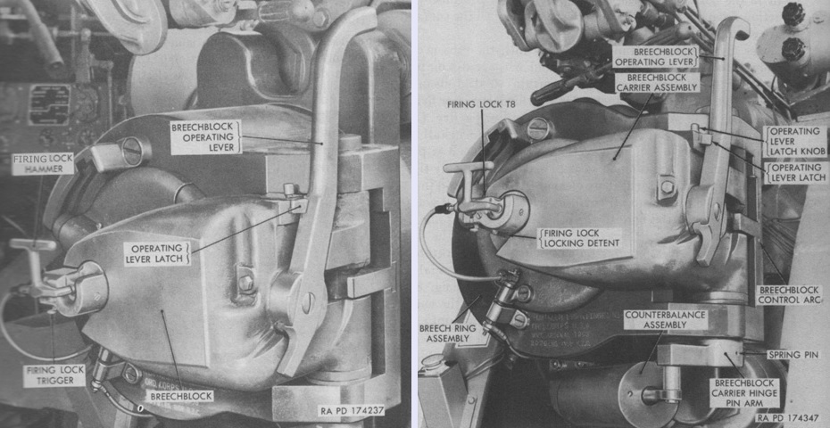
The breech is closed in these images, with the operating handle visible on the right. (Picture from TM 9-7004 Self-propelled 155-mm Howitzer T194.)
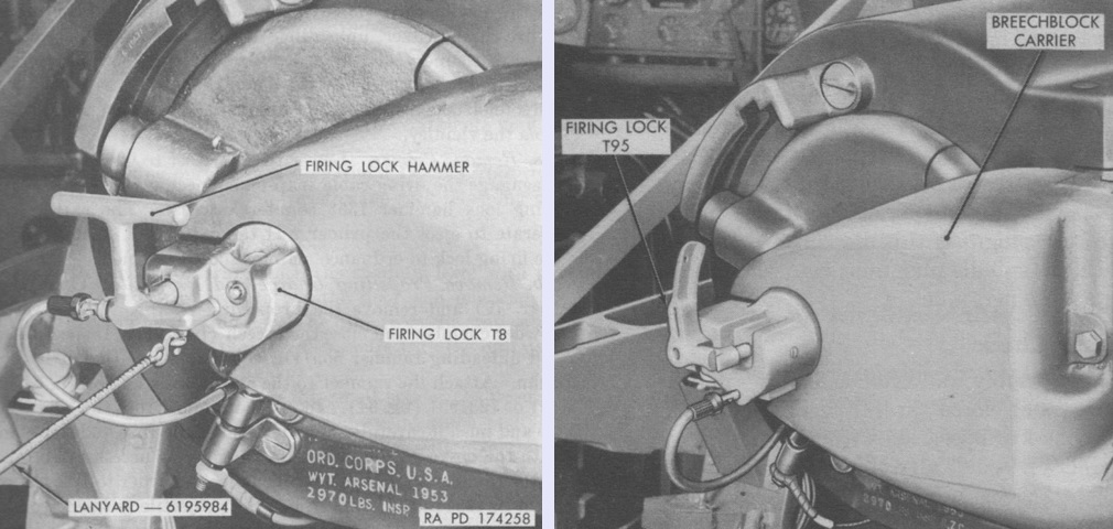
The firing lock T8 consisted of a housing that enclosed and supported the actuating mechanism for opening and closing the primer cartridge case. The device also fired the primer, either mechanically or electrically. The hammer combined the functions of an operating handle, a percussion hammer, and an electrical conduit. The firing lock T95 functioned in a similar manner. (Picture from TM 9-7004 Self-propelled 155-mm Howitzer T194.)
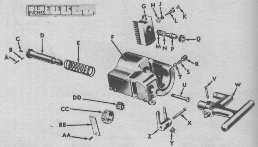
An exploded view of the firing lock T8 is provided in this image. A. Hammer stem guide pin. B. Hammer stem guide pin spring. C. Hammer stem guide pin retaining screw. D. Firing lock hammer stem. E. Firing spring. F. Firing lock housing group. G. Firing lock wedge. H. Firing lock extractor pawl. J. Extractor pawl shaft spring. K. Extractor pawl shaft retaining screw. L. Extractor pawl shaft. M. Firing pin retracting spring. N. Firing pin spacer. P. Firing pin. Q. Firing pin bushing. R. Wedge plunger spring retainer. S. Firing lock wedge plunger spring plunger spring. T. Firing lock wedge plunger. U. Firing lock pinion shaft. V. Firing lock hammer stem screw stem screw. W. Firing lock hammer group. X. Firing lock extractor pin. Y. Primer extractor spring. Z. Primer extractor. AA. Firing lock housing plate screw. BB. Firing lock housing plate. CC. Firing lock gear. DD. Firing lock pinion. (Picture from TM 9-7004 Self-propelled 155-mm Howitzer T194.)
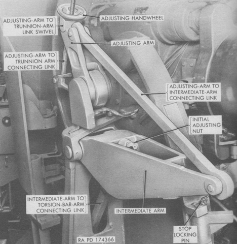
A torsion bar equilibrator was secured to the left side of the howitzer mount and helped balance the weight of the howitzer and mount tipping parts. It was set from the factory to approximately balance the mount on level ground; on slopes it was possible to adjust the equalization with the adjusting handwheel. (Picture from TM 9-7004 Self-propelled 155-mm Howitzer T194.)
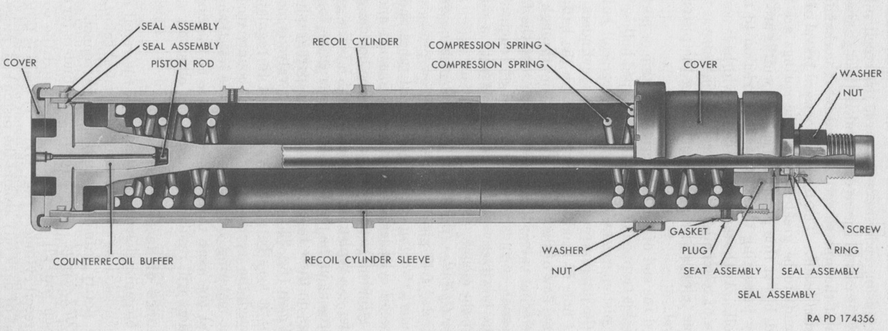
A cross-section of a hydrospring recoil cylinder is drawn above. Four recoil cylinders were used, mounted in pairs above and below the ordnance. Each cylinder had two helical compression springs that were installed between the piston rod head and the seat assembly. The piston rods were attached to the breech, and were pulled to the rear as the breech moved rearward under the force of recoil. The springs were compressed, and oil in the cylinder was forced through tapered grooves in the inside surface of the cylinder sleeve as the piston head moved to the rear. The compression of the springs and the resistance of the oil combined to arrest the movement of the howitzer, and the springs then expanded to return the ordnance to battery. As the piston rod neared the end of its forward travel, oil that had become trapped in the tapered hollow at the front of the piston was forced through a small hole in the counterrecoil buffer via a metering valve. This resistance prevented the howitzer from returning to battery with undue force. Normal recoil length was 19¼" (48.90cm), and maximum was 19⅜" (49.213cm). Including the two replenisher cylinders, the recoil mechanism had a capacity of 9.7gal (37L) of oil. (Picture from TM 9-7004 Self-propelled 155-mm Howitzer T194.)
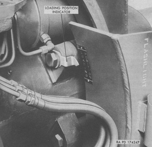
A loading position indicator was found on the right side of the howitzer mount. During loading, the howitzer was to be depressed until the pointer was between the white lines on the indicator. (Picture from TM 9-7004 Self-propelled 155-mm Howitzer T194.)
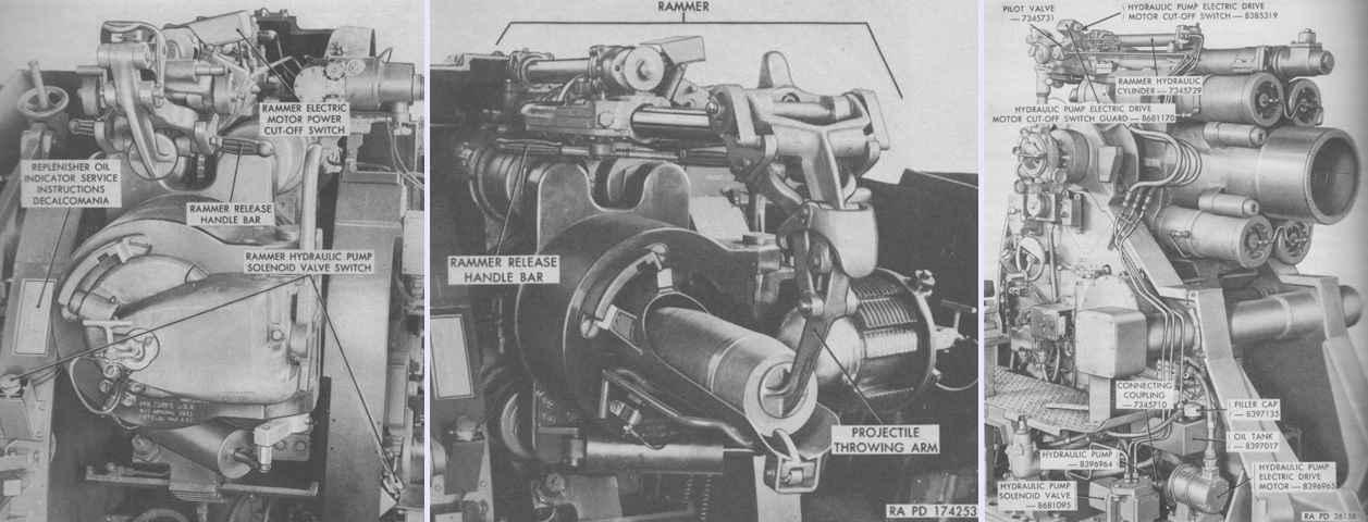
An hydraulic rammer assisted with loading the howitzer. Its controls are labeled on the left, and its hydraulic system is detailed on the right with the howitzer absent. In the center, the rammer is depicted in action. With a projectile on a loading tray positioned firmly in the breech recess, the rammer was fully extended, thereby locking the ram rod, and the rammer head was manually positioned behind the projectile. The rammer release handle bar was then operated to release the ram rod, freeing the throwing arm to ram the projectile into the breech. The rammer's hydraulic pump drive motor was a Lamb Electric Co., of Kent, Ohio, model E3700-2, a 24-volt, 4 pole compound-wound motor that produced 1½hp. The vane-type hydraulic pump was a Vicker's, Inc., of Detroit, model VT4-100-15-100-10S2 with an integral relief valve set at 1,000psi (70.3kg/cm²). The pump had a normal rating of 1.5gpm (5.7L/min) at 1,200rpm. Three quarts (2.8L) of oil was used. (Pictures from TM 9-7004 Self-propelled 155-mm Howitzer T194 and TM 9-7005.)
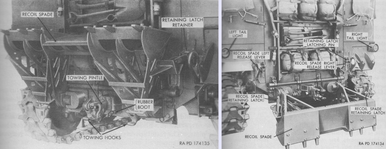
The recoil spade is shown in the raised and lowered positions on the left and right above, respectively. A latch on each side secured the spade in the raised position, and release levers allowed the spade to be lowered. (Picture from TM 9-7004 Self-propelled 155-mm Howitzer T194.)
Manufactured by the Consolidated Welding and Engineering Company of Chicago, the spade's 348lb (158kg) weight was cushioned upon release by two torsion bars that ran under the vehicle floor. The torsion bars were meshed to the spade by bevel gears and pinions. The torsion bars provided some assistance when stowing the spade, but nonetheless three men were required when raising it.
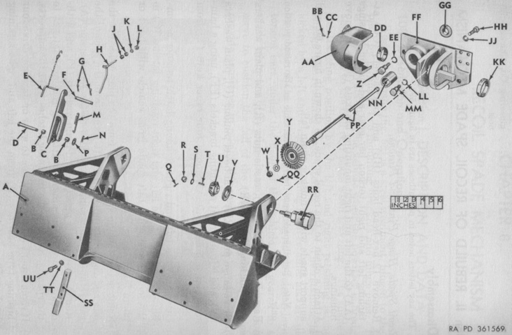
A. Recoil spade. B. Bushing-type bearing (0.9420" [2.393cm] OD, ½" [1.3cm] long). C. Retaining latch. D. 0.7480 x 3⅝ (1.900cm x 9.208cm) clevis pin. E. Retaining latch retainer assembly. F. Retaining latch latching pin (0.7480 x 4-5/16 [1.900cm x 10.954cm]). G. Retaining clip (¾" [1.9cm] diam). H. Retaining latch release lever. J. Bushing-type bearing (0.8150" [2.070cm] OD, 21/32" (1.6669cm] long). K. ½" (1.3cm) lockwasher. L. ½-20NF-2 hex jam nut. M. Tension spring (25/32" [1.9844cm] OD, 11 coils). N. 5/32 x 1¼ (.39688cm x 3.18cm) cotter pin. P. Plain washer (13/16" [2.064cm] OD, 1½" [3.8cm] ID, 0.1340" [0.3404cm] thick). Q. 3/16 x 1½ (.4763cm x 3.8cm) cotter pin. R. ¾-16NF-2 castle nut. S. Plain washer (25/32" [1.9844cm] ID, 1-5/16" [3.3338cm] OD, 0.0950" [0.2413cm] thick). T. ¼ (.64cm) square x 1-5/16 (3.3338cm) taper key. U. Bevel pinion. V. Plain washer (1¼" [3.18cm] ID, 3¼" [8.26cm] OD, ¼" [.64cm] thick). W. ¾-16NH-2 castle nut. X. Plain washer (13/16" [2.064cm] ID, 1½" [3.8cm] OD, 0.1340" [0.3404cm] thick). Y. Bevel gear. Z. ¾-16NL-2 x 3 hex-head shoulder bolt. AA. Torsion bar gear and pinion housing. BB. ¼-28NF-3 x ½ hex-head bolt. CC. ¼" (.64cm) lockwasher. DD. Bushing-type bearing (2.6280" [6.6751cm] OD, 31/32" [2.4606cm] long). EE. ⅞" (2.22cm) lockwasher. FF. Mounting bracket. GG. Bracket-to-hull mounting grommet. HH. ¾-16NF-2 x 2¼ hex-head bolt. JJ. ¾" (1.9cm) lockwasher. KK. Bushing-type bearing (3.5660" [9.0578cm] OD, 31/32" [2.4606cm] long). LL. ⅞" (2.22cm) lockwasher. MM. ¾-16NF-2 x 2½ hex-head shoulder bolt. NN. Bushing-type bearing (2.3790" [6.0423cm] OD, 2½" [6.4cm] long). PP. Torsion bar. QQ. 3/16 x 1½ (.4763cm x 3.8cm) cotter pin. RR. Hinge pin. SS. Spike. TT. ¾" (1.9cm) lockwasher. UU. ¾-16NF-2 x 1¾ hex-head bolt. (Picture from TM 9-7005.)
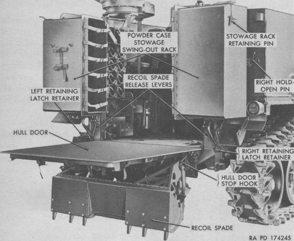
Once the spade was released, the rear hull door was unlocked using a latch on each side and lowered to provide additional working surface for the howitzer crew. (Picture from TM 9-7004 Self-propelled 155-mm Howitzer T194.)
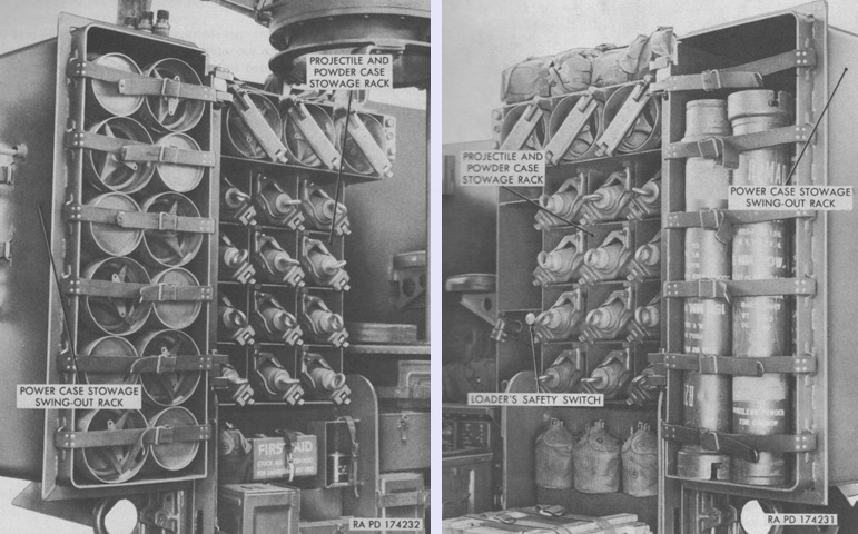
Projectiles and propellant were stowed at the rear of the fighting compartment. The projectile and powder case stowage racks on each side held twelve projectiles and three powder cases, and the hinged powder case stowage swing-out racks could be secured in the open position out of the crew compartment with a locking pin. (Picture from TM 9-7004 Self-propelled 155-mm Howitzer T194.)
The rear door and recoil spade are lowered on this vehicle. The projectile and propellant charge stowage rack can be seen in the cab's left rear corner, and the loader's and driver's seats can be seen in front of the machine gun mount. Radio equipment is stowed on the floor along the cab's left side.
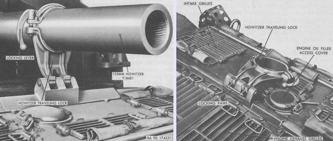
The howitzer travel lock is seen in use on the left and stowed on the right. When folded forward, it was automatically secured by a locking pawl. To erect the travel lock, the locking pawl was pulled upward. (Picture from TM 9-7004 Self-propelled 155-mm Howitzer T194.)
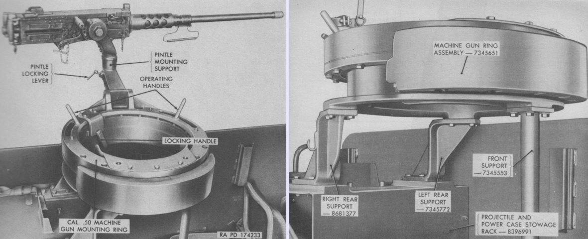
The machine gun ring mount had a backrest for the operator, and two operating handles eased traverse. The ring mount and the pintle mount each had their own locking handles. The attachment points and supports for the ring mount are seen on the right. (Picture from TM 9-7004 Self-propelled 155-mm Howitzer T194.)
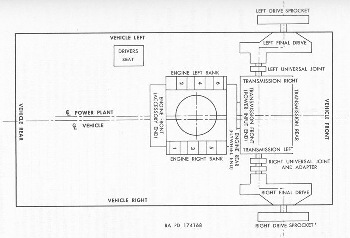
A top-down sketch of the powertrain shows that it was slightly offset from the vehicle centerline. Despite facing the rear of the vehicle, the accessory end of the engine was considered the front. The engine's left and right sides were determined by looking at the engine from the accessory end. (Picture from TM 9-7004 Self-propelled 155-mm Howitzer T194.)
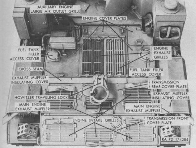
The engine compartment grilles and cover plates are installed and labeled. The structure between the right-side fuel tank filler access cover and the auxiliary engine large air outlet grille is the auxiliary engine air intake shroud. Note that the main engine muffler orientation is opposite that found on the 105mm SPH M52. (Picture from TM 9-7004 Self-propelled 155-mm Howitzer T194.)
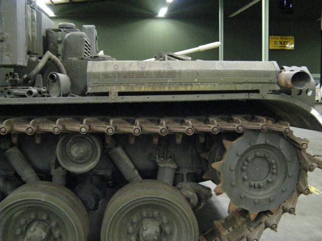
The main engine mufflers were mounted on the vehicle's front fenders, and the muffler for the auxiliary engine was placed behind the right-hand main engine muffler.
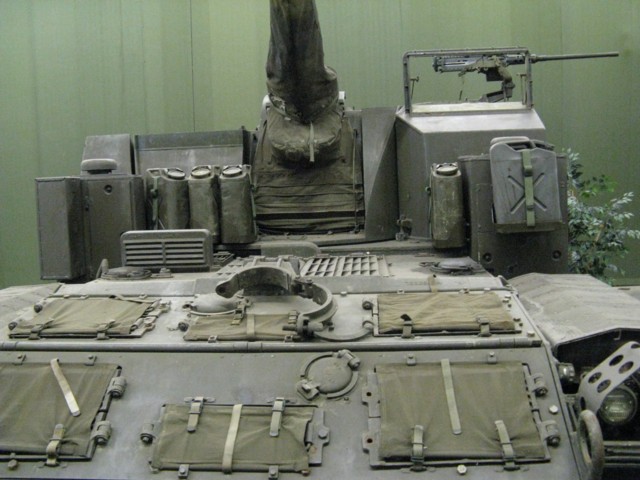
The canvas covers on the vehicle's front slope are covering the engine air intake grilles, while the engine exhaust grilles close to the cab are uncovered. The howitzer travel lock is folded down, and various filler caps can also be seen on the front of the vehicle. The engine's air cleaners are mounted on the front corners of the cab, atop which are their mushroom-like vent breathers. The fire extinguisher service door is on the front of the right-hand engine air cleaner box.
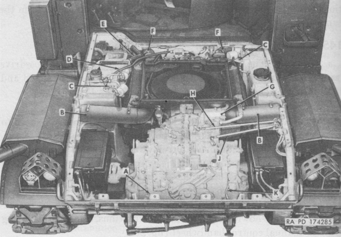
The engine compartment is seen here with the covers removed. The transmission is at the front with the engine behind it, and batteries flank each side of the transmission. The letters refer to disconnect points when removing the power plant assemblies. (Picture from TM 9-7004 Self-propelled 155-mm Howitzer T194.)
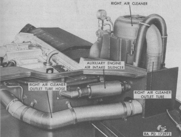
The right main engine air cleaner is seen with the cab removed. An oil cup at the bottom of the cleaner absorbed dirt filtered from the air. (Picture from TM 9-7004 Self-propelled 155-mm Howitzer T194.)
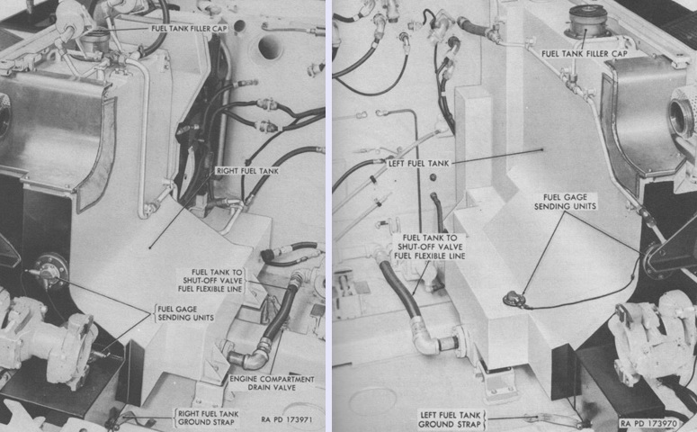
A welded steel fuel tank was installed on each side of the engine, formed to project under the engine cylinders. (Picture from TM 9-7004 Self-propelled 155-mm Howitzer T194.)
This image shows a cross-section of a road wheel and its swing arm and torsion bar. (Picture from ORD 9 SNL G-279.)
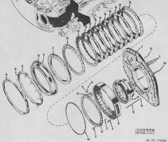
The right-side brake and endplate is detailed in this diagram. "G" and "H" are brake discs. (Picture from ORD 9 SNL G-279.)
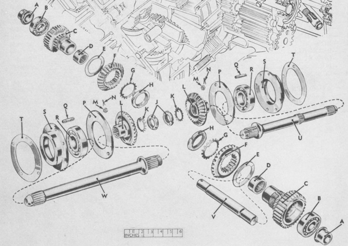
The steering differential is shown in exploded form. (Picture from ORD 9 SNL G-279.)
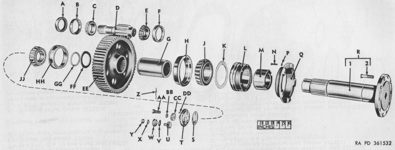
Final drive components are revealed in this picture. Manufactured by the Massey-Harris Company of Racine, Wisconsin, each final drive had a spur gear reduction consisting of a 13-tooth input gear and a 61-tooth output shaft gear, for a final output reduction of 4.69:1. Each final drive weighed 495lb (225kg) and contained 6 quarts (5.7L) of oil.
A. 4.2540" (10.805cm) OD oil seal. B. 4.4375" (11.271cm) OD bearing cup. C. 2.5000" (6.3500cm) bore bearing cone. D. Input gear. E. 2.5000" (6.3500cm) bore bearing cone. F. 4.4375" (11.271cm) OD bearing cup. G. Output shaft gear outer spacer. H. 7.5000" (19.050cm) OD bearing cup. J. 4.0000" (10.160cm) bore bearing cone. K. Oil seal cartridge gasket. L. Oil seal cartridge. M. Output shaft outer bearing spacer. N. ⅜-16NC-2 x 1½ hex-head bolt. P. ⅜" (.953cm) lockwasher. Q. Oil seal cartridge dirt guard. R. Output shaft assembly: 1. Output shaft. 2. ¾-16NF-2 x 3-1/16 shoulder bolt. S. Output shaft adjusting shim (0.005" [0.013cm], 0.007" [0.018cm], or 0.010" [.025cm] thick). T. Output shaft retainer. U. Speedometer drive shaft lower drive gear (left final drive). V. Lower drive gear bearing guard (left final drive). W. 1.6535" (4.1999cm) OD lower drive gear ball bearing (left final drive). X. 0.6060" (1.539cm) bore ball bearing lockwasher. Y. 0.586-32NS-3 ball bearing locknut. Z. 0.0625" (0.1588cm) diam locking wire. AA. ⅝-18NF-2 x 1¾ hex-head bolt. BB. Snap ring. CC. Speedometer drive shaft upper drive gear. DD. 3/32 x ½ (0.23813cm x 1.3cm) woodruff key. EE. Output shaft gear. FF. Output shaft gear washer. GG. Output shaft gear inner spacer. HH. 6.3750" (16.193cm) OD bearing cup. JJ. 3.2500" (8.2550cm) bore bearing cone. (Picture from TM 9-7005.)
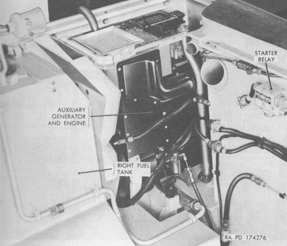
The Delco Products Division A-8585 auxiliary generator and General Motors A-41-1 engine were installed in the engine compartment behind the right fuel tank. The engine could be started either electrically by a switch below and behind the commander's position or manually by a starting handle on the engine itself. (Picture from TM 9-7004 Self-propelled 155-mm Howitzer T194.)
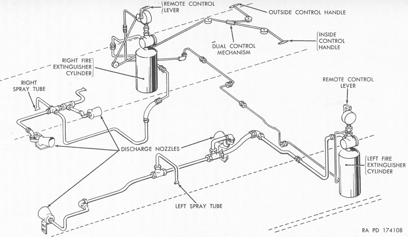
The fixed fire extinguisher system was fed by two 10lb (4.5kg) CO2 bottles installed on the hull sponsons, with the right one inside the air cleaner compartment and the left below the driver's instrument panel. Four nozzles were used, with one discharging onto the transmission, two onto the main engine, and the fourth toward the auxiliary engine. Two spray tubes were directed to discharge between the the fuel tanks and the hull. (Picture from TM 9-7004 Self-propelled 155-mm Howitzer T194.)
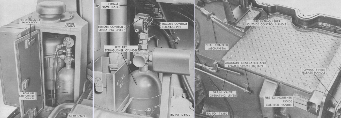
The right and left fixed fire extinguisher bottles are shown installed above at the left and center, respectively. The bottles could be discharged by remote control levers on their heads, or by control handles on the inside and outside of the right sponson, as seen at the right with the cab removed. (Picture from TM 9-7004 Self-propelled 155-mm Howitzer T194.)
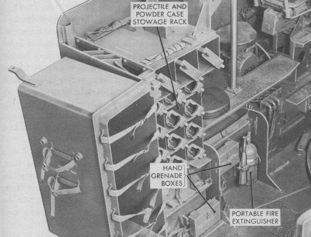
In addition to the fixed system, a 5lb (2.3kg) portable extinguisher was secured to the left hull wall. (Picture from TM 9-7004 Self-propelled 155-mm Howitzer T194.)
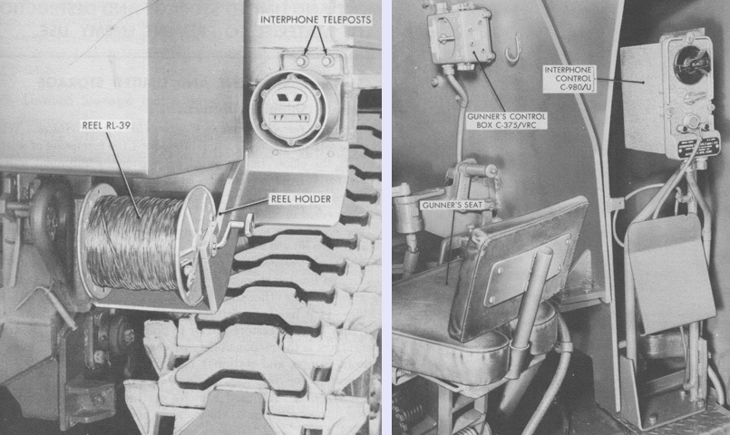
A holder for a reel RL-39 and spool DR-8 was found on the right rear corner of the hull, allowing the laying and recovery of light field wire. The wire was connected to one of the interphone teleposts above the right tail light, and the other end of the wire to the firing battery control station, or field telephone or switchboard. The interphone teleposts connected to the terminal posts on the interphone C-980/U located to the right of the turret. This allowed push to talk communication between any of the crew's intercom control boxes and the external telephone. (Picture from TM 9-7004 Self-propelled 155-mm Howitzer T194.)
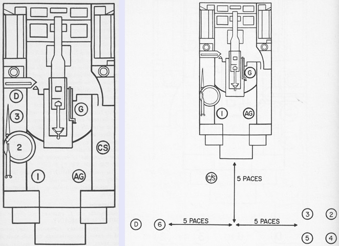
The mounted positions of the howitzer section are shown on the left. Six cannoneers were members of the section (labeled 1-6), but only three were able to ride in the howitzer. The section is depicted deployed and ready for action on the right, with the other three cannoneers joining from the support vehicle. (Pictures from FM 6-92 155-mm Howitzer M44, Self-propelled.)
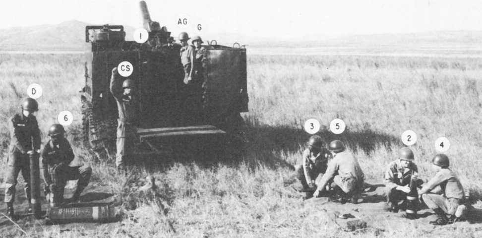
An actual howitzer section is shown here with the ordnance loaded and ready to fire. (Picture from FM 6-92 155-mm Howitzer M44, Self-propelled.)
