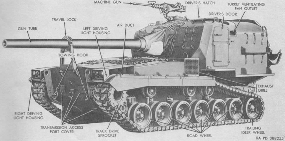
155mm Self-propelled Gun M53.

The M53 used a reversed drivetrain compared to the tanks on which it was based, with the transmission, engine, and drive sprocket to the front of the vehicle and the large turret, which housed all crewmembers, to the rear. The vehicle pictured may be a pilot, as on production vehicles the three upper transmission access ports were in a straight line across the hull. The vertical skirts hinged to the fenders were provided on vehicles through serial number 338. (Picture from TM 9-2350-210-12 Operation and Organizational Maintenance 155-mm Self-propelled Gun Cannon M52 (T97) and 8-inch Self-propelled Howitzer Cannon M55 (T108).)
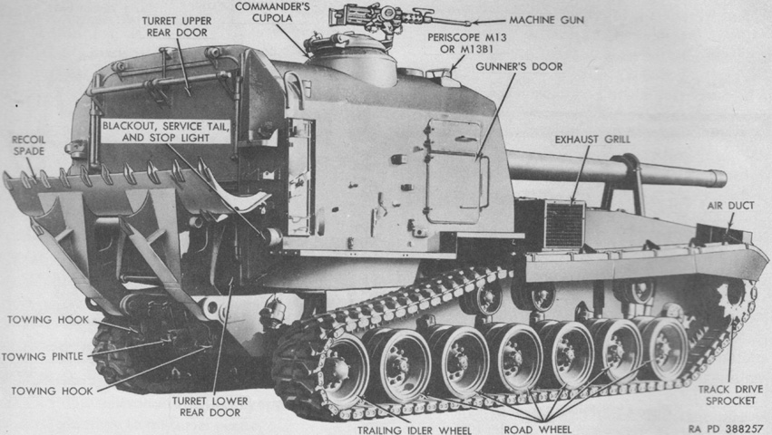
The large recoil spade is secured in its travel position, blocking the turret lower rear door. A rack for pioneer tools is attached to the turret's right rear corner, adjacent to the water can rack. (Picture from TM 9-2350-210-12 Operation and Organizational Maintenance 155-mm Self-propelled Gun Cannon M52 (T97) and 8-inch Self-propelled Howitzer Cannon M55 (T108).)
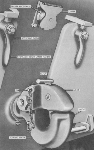
A towing pintle was found on the hull rear and was flanked on each side by stowage compartments secured by latching doors. (Picture from TM 9-2350-210-12 Operation and Organizational Maintenance 155-mm Self-propelled Gun Cannon M52 (T97) and 8-inch Self-propelled Howitzer Cannon M55 (T108).)
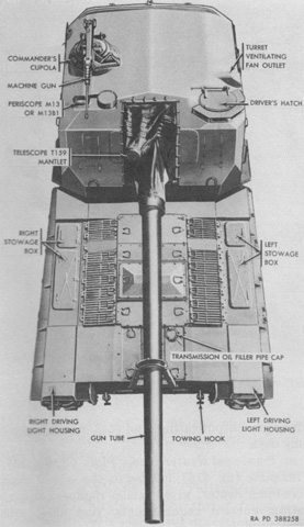
The locations of the driver and gunner at the turret's front left and right corners, respectively, can be gleaned from this angle. The gunner was provided with a periscope M13 or M13B1 for wide field of view. This 1x device had a 90° horizontal and 25° vertical field of view. The commander was behind the gunner on the turret right. (Picture from TM 9-2350-210-12 Operation and Organizational Maintenance 155-mm Self-propelled Gun Cannon M52 (T97) and 8-inch Self-propelled Howitzer Cannon M55 (T108).)

The underside of the hull is labeled on the left, with the production arrangement of the transmission access covers. The covers are shown open on the right. The legend for the left image is: A. Transmission access port plate. B. Transmission access port cover. C. ⅝ x 2¼ in. (1.59cm x 5.72cm) self-locking hex-head bolt. D. Transmission oil drain plug access port plate. E. ⅝ x 1¾ in. (1.59cm x 4.45cm) self-locking hex-head bolt. F. Engine oil drain plug access port plate. G. Fuel tank drain access port cover. H. Turret support compartment drain. J. Engine compartment drain. K. Engine oil filter access port plate.
The legend for the right image is: A. Right brake adjustment inspection hole plug. B. Adjusting screw retainer. C. Reverse-range band adjusting screw. D. Power takeoff access port cover. E. Low-range band adjusting screw. F. Left brake inspection hole plug. G. Oil drain plug access port. H. ⅜ x ¾ in. (.953cm x 1.9cm) self-locking bolt. J. 7/16 in. (1.111cm) flat washer. (Pictures from TM 9-2350-210-12 Operation and Organizational Maintenance 155-mm Self-propelled Gun Cannon M52 (T97) and 8-inch Self-propelled Howitzer Cannon M55 (T108).)
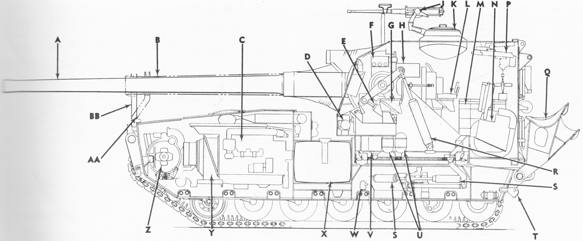
This elevational cross-section depicts both the M53 and the 8" self-propelled howitzer M55, and the difference in the size of their ordnances is apparent. The hull was divided by bulkheads into four compartments; from front to rear these were the engine compartment, fuel tank compartment, turret support compartment, and rear stowage compartment. The hull was strengthened by the torsion bar covers welded to the floor, and the turret support compartment was reinforced to withstand the forces of firing the piece. A. 155-mm gun M46 (T80). B. 8-inch howitzer M47 (T89). C. Engine. D. Personnel heater (left). E. Equilibrator vertical adjusting cylinder. F. Main instrument panel. G. Driver's seat. H. Recoil cylinder. J. Caliber .50 machine gun M2. K. Commander's cupola. L. Commander's seat. M. Projectile rack. N. Projectile rammer and spade hoist. P. Ammunition hoist (M55 [T108] only). Q. Recoil spade. R. Vertical equilibrator cylinder. S. Horizontal equilibrator cylinder. T. Towing pintle. U. Equilibrator gas bottle. V. Equilibrator accumulator. W. Bilge pump (early-production vehicles only). X. Fuel tank. Y. Oil cooler. Z. Transmission. AA. Travel lock (M55 [T108]). BB. Travel lock (M53 [T97]). (Picture from TM 9-2350-210-12 Operation and Organizational Maintenance 155-mm Self-propelled Gun Cannon M52 (T97) and 8-inch Self-propelled Howitzer Cannon M55 (T108).)
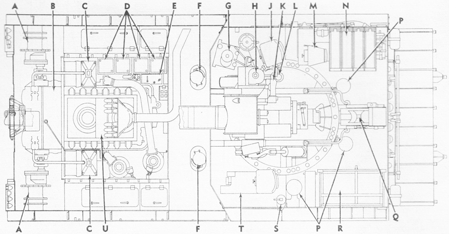
A cross-section plan view is sketched. A. Final drive. B. Transmission. C. Oil cooler. D. Batteries. E. Auxiliary generator and engine. F. Fuel filler cap cover. G. Elevating and traversing system hydraulic pump unit. H. Panoramic telescope M100 (T149E1). J. Gunner's seat. K. Telescope M99 (T159E1). L. Azimuth indicator T27. M. Commander's seat. N. Projectile rack. P. Turret seat. Q. Projectile rammer and spade hoist. R. Powder containers rack. S. Turret ventilating fan. T. Driver's seat. U. Engine. (Picture from TM 9-2350-210-12 Operation and Organizational Maintenance 155-mm Self-propelled Gun Cannon M52 (T97) and 8-inch Self-propelled Howitzer Cannon M55 (T108).)
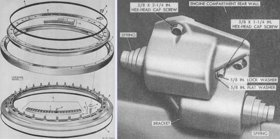
An exploded view of the turret bearing is provided on the left. It consisted of upper and lower roller assemblies. The lower roller assembly supported the turret's weight and was mounted horizontally, while the upper roller assembly was mounted at a 45° angle to the lower, and helped absorb recoil forces. A. Seal. B. Ring. C. Bearing, assy. 1. Roller. 2. Retainer. D. Nut. E. Washer. F. Ring. G. Base. H. Seal. J. Stud. K. Wheel. L. Bolt. M. Washer. N. Rack. P. Bearing, assy. 1. Retainer. 2. Roller.
The turret was prevented from rotating beyond its traversing limits by the turret limiting bumper shown on the right, which was a set of two volute springs attached to the air exhaust duct rear wall. Stops welded to the front wall of the turret contacted the springs when traversed to the limits. (Pictures from ORD 9 SNL G-259 List of All Service Parts of Gun, Self-propelled, Full Tracked: 155-mm, T97 and Howitzer, Self-propelled, Full Tracked: 8-in, T108 and TM 9-2350-210-12 Operation and Organizational Maintenance 155-mm Self-propelled Gun Cannon M52 (T97) and 8-inch Self-propelled Howitzer Cannon M55 (T108).)
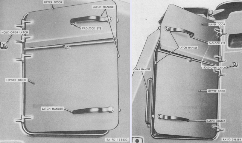
The driver and gunner each had a two-section interlocking door in their respective turret side for access to the turret interior. (Picture from TM 9-2350-210-12 Operation and Organizational Maintenance 155-mm Self-propelled Gun Cannon M52 (T97) and 8-inch Self-propelled Howitzer Cannon M55 (T108).)
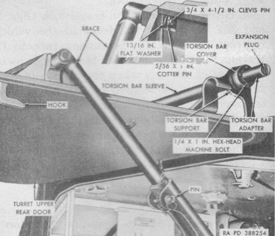
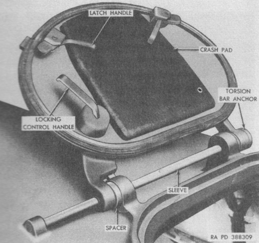
The turret rear doors were each counterbalanced by a torsion bar incorporated into their hinges, as seen in this image of the upper door. When opened, the doors could be secured by jointed-steel braces as shown. (Picture from TM 9-2350-210-12 Operation and Organizational Maintenance 155-mm Self-propelled Gun Cannon M52 (T97) and 8-inch Self-propelled Howitzer Cannon M55 (T108).)
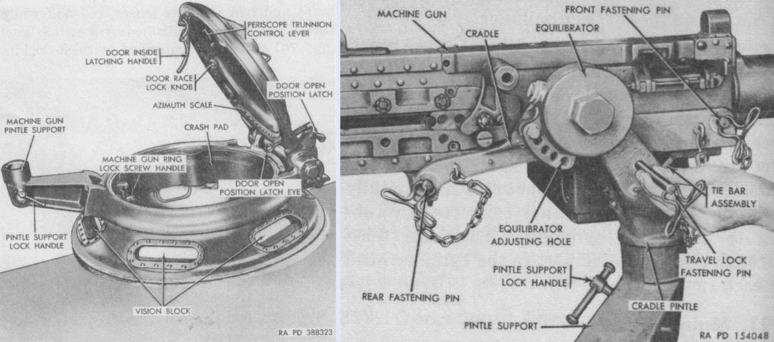
The commander's cupola had a ring of vision blocks in the base, and a rotating race in the door that could be fitted with a periscope. The machine gun mount is detailed on the right. The cradle could be fixed to the equilibrator in any of five positions, with resultant changes to gun balance. The machine gun could be secured for travel by turning the machine gun ring locking screw handle in the cupola interior and inserting the travel lock fastening pin, which fixed the cradle to the cradle pintle. (Picture from TM 9-2350-210-12 Operation and Organizational Maintenance 155-mm Self-propelled Gun Cannon M52 (T97) and 8-inch Self-propelled Howitzer Cannon M55 (T108).)
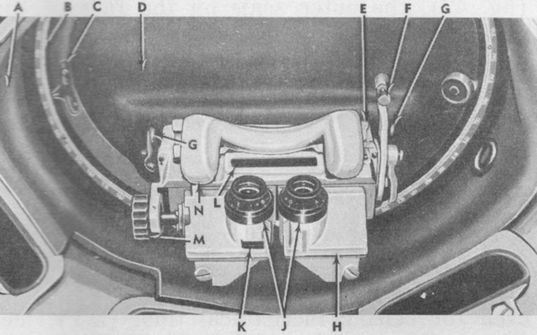
The commander's periscope M15A1 was used for general observation and for ranging or sighting on a target. It was a binocular device with a 1x optical system with a 60° horizontal and 10°20' vertical field of view, and a 7x system with a 10° field of view. An azimuth scale numbered from 0 to 6,400 mils in 100-mil intervals and 10-mil intermediate intervals was secured to the underside of the door race ring. A. Cupola race ring. B. Azimuth scale. C. Azimuth pointer. D. Cupola door plate. E. Periscope holder. F. Elevation arm adjusting knob. G. Periscope trunnion control lever. H. Periscope. J. Eyepiece. K. Lamp bracket slot. L. Observation window. M. Interpupillary knob. N. Headrest. (Picture from TM 9-2350-210-12 Operation and Organizational Maintenance 155-mm Self-propelled Gun Cannon M52 (T97) and 8-inch Self-propelled Howitzer Cannon M55 (T108).)
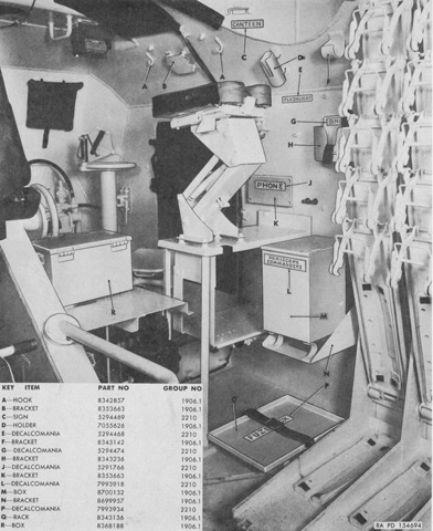
The turret interior is seen here from the left rear. Shell racks are visible on the right, and the commander's elevated seat can be seen near the center of the image. (Picture from ORD 9 SNL G-259 List of All Service Parts of Gun, Self-propelled, Full Tracked: 155-mm, T97 and Howitzer, Self-propelled, Full Tracked: 8-in, T108.)
The driver's hatch was also counterbalanced by a torsion spring. The driver was provided with four periscopes M17, which were unity optics with a 150° horizontal and 50° vertical field of view, for a total horizontal field of view of ~225°. (Picture from TM 9-2350-210-12 Operation and Organizational Maintenance 155-mm Self-propelled Gun Cannon M52 (T97) and 8-inch Self-propelled Howitzer Cannon M55 (T108).)
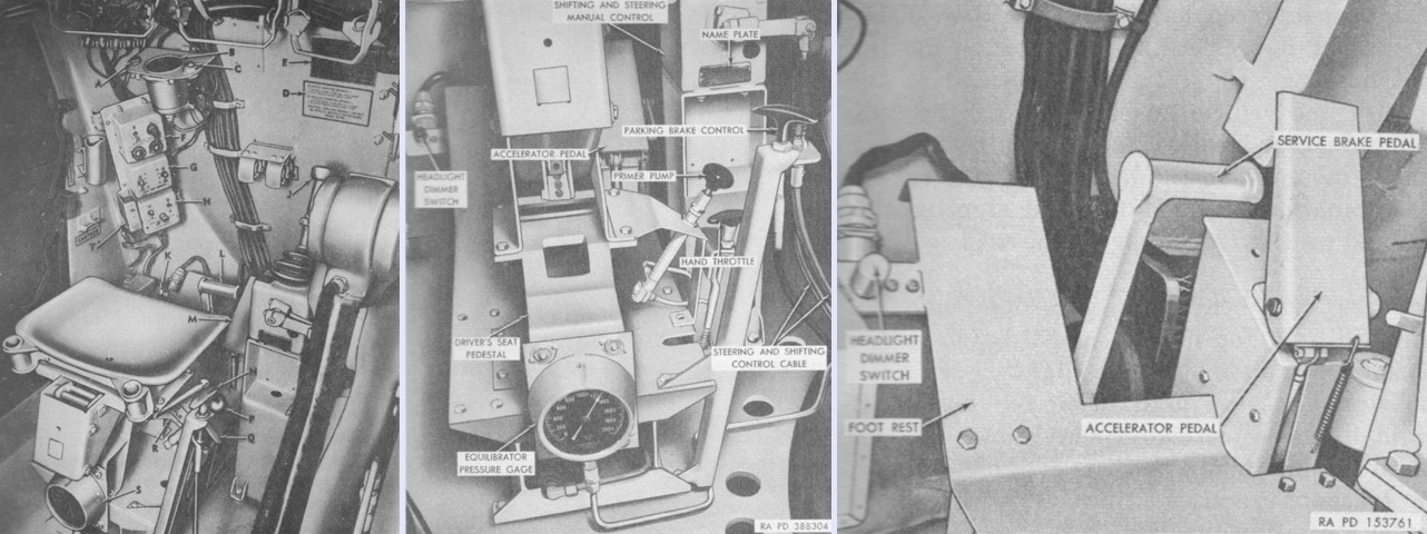
Three views of the driver's area are given above. An overview of his controls and instruments is on the left, with his seatback removed for clarity. In the center, the controls and instruments mounted on his seat pedestal are detailed. Finally, the driver's control pedals are shown on the right. The legend for the left image is: A. Horn switch. B. Speedometer-tachometer indicator. C. Master warning light. D. Parking brake caution and instruction decalomania. E. Vehicle name plate. F. Auxiliary generator and engine control panel. G. Bilge pump control panel. H. Personnel heater control panel. J. Shifting and steering manual control. K. Headlight dimmer switch. L. Service brake pedal. M. Accelerator pedal. N. Parking brake control. P. Primer pump. Q. Hand throttle. R. Driver's seat vertical release lever. S. Equilibrator pressure gage. T. Heater emergency switch. (Picture from TM 9-2350-210-12 Operation and Organizational Maintenance 155-mm Self-propelled Gun Cannon M52 (T97) and 8-inch Self-propelled Howitzer Cannon M55 (T108).)
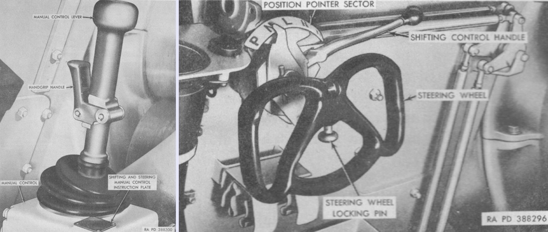
Vehicles up to no.209 were built with the shifting and steering manual control lever seen on the left, while subsequent machines changed to the steering wheel and gearshift shown on the right. The shifting and steering manual control lever steered the vehicle when moved side to side, and shifted between shift ranges when moved fore and aft. Front to rear, the range positions for the lever were neutral, high, low, and reverse. When shifting into or from neutral or into reverse from high or low range, the handgrip handle needed to be squeezed. The shifting control handle behind the steering wheel added a fifth position for park. The steering wheel locking pin secured the wheel in either the raised or lowered positions. (Picture from TM 9-2350-210-12 Operation and Organizational Maintenance 155-mm Self-propelled Gun Cannon M52 (T97) and 8-inch Self-propelled Howitzer Cannon M55 (T108).)
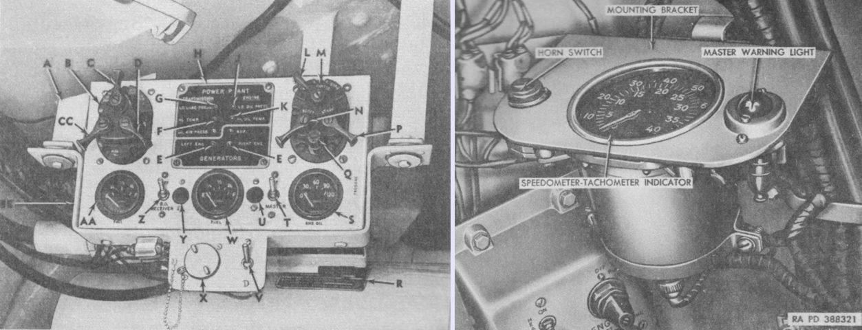
The driver's main instrument panel is labeled on the left, and the speedometer-tachometer indicator in the right image denoted speed in mph with the outer calibrations and engine rpm with the dial's inner calibrations. An odometer was also present. The legend for the left image is: A. Vertical bracket. B. Lighting control switch. C. Light control switch lever. D. Locking lever. E. Generator warning light. F. Transmission oil high temperature warning light. G. Transmission oil low pressure warning light. H. Warning light plate. J. Engine oil low pressure warning light. K. Engine oil high temperature warning light. L. Magneto switch lever. M. Magneto and starter with degasser switch. N. Booster switch lever. P. Starter switch lever. Q. Degasser switch plunger. R. Gun mount name plate. S. Engine oil pressure indicator. T. Master relay switch lever. U. Master relay indicator light. V. Infrared selector switch. W. Right fuel tank gage. X. Power outlet socket and plug. Y. High-beam indicator light. Z. Blackout receiver switch. AA. Left fuel tank gage. BB. Instrument panel front bracket. CC. Parking light switch lever. (Picture from TM 9-2350-210-12 Operation and Organizational Maintenance 155-mm Self-propelled Gun Cannon M52 (T97) and 8-inch Self-propelled Howitzer Cannon M55 (T108).)
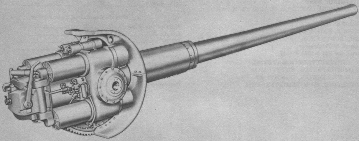
The 155mm gun M46 is shown in the 155mm and 8" gun mount M86. The gun was principally built up from the firing lock, breechblock counterbalance assembly, breech mechanism group, and gun tube and breech ring group. The mount included the hydrospring recoil mechanism and replenisher assemblies and the cradle group. The tube was supported and aligned in the mount by finish-machined bearing surfaces on the tube's rear half. A torque key in the lower front portion of the cradle prevented rotation of the tube. Overall length of the cannon and mount was 291¾" (741.05cm), width was 46¼" (117.5cm), and height was 49" (124cm). The complete cannon weighed 7,168lb (3,251kg), with the tube comprising 5,825lb (2,642kg) of that. The mount weighed 4,800lb (2,200kg), and the recoil mechanism's four recoil cylinders and replenisher assembly contained 25 gallons (95L) of fluid. The gun tube's estimated accuracy life was 1,800 rounds. (Picture from TM 9-500 C3 Data Sheets for Ordnance Type Materiel.)
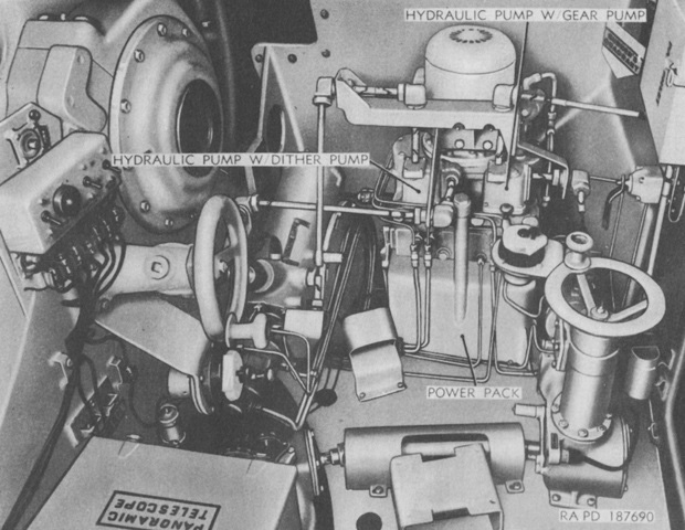
An early version of the gunner's traversing and elevation system is labeled here. (Picture from TM 9-7205-2.)
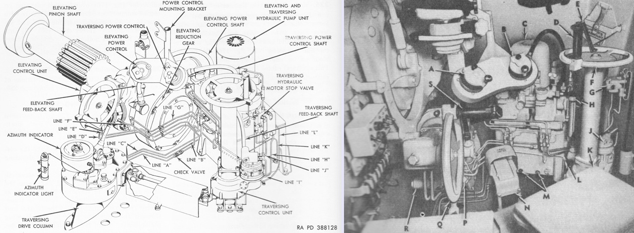
The production elevating and traversing system is diagrammed on the left, with the gunner's controls labeled on the right. The system held ~9.25 gallons (35.0L) of oil. The legend for the right image is: A. Elevating power control. B. Traversing power control. C. Elevating and traversing hydraulic pump unit. D. Handle. E. Lever. F. Manual traversing handwheel. G. Traversing hydraulic motor stop valve. H. Filler cap. J. Traversing hydraulic motor. K. Gunner's seat. L. Loop clamp. M. Drain plug. N. Foot firing switch. P. Motor pawl cap. Q. Elevating manual handwheel. R. Elevating hydraulic motor. S. Handle. (Picture from TM 9-2350-210-12 Operation and Organizational Maintenance 155-mm Self-propelled Gun Cannon M52 (T97) and 8-inch Self-propelled Howitzer Cannon M55 (T108).)
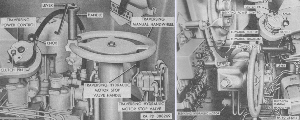
A closer look at the traverse and elevation controls is provided here. Clutch pins in the elevation and traverse power control knobs permitted the gunner to select either 5:1 or 1:1 gear ratios by pulling out or pushing in the knobs, respectively, for rapid or fine elevation and traverse. When the elevation and traverse pump units were on, hydraulic oil was sent to the hydraulic motor latch pawl ports at 120psi (8.4kg/cm²), disengaging the pawls and permitting the motors to operate. Maximum traverse rate was ~10.1°/sec with the 5:1 ratio and ~3.0°/sec with the 1:1 ratio. Maximum elevation rate with the 5:1 ratio was ~7.5°/sec, and ~1.5°/sec with the 1:1 ratio. With the powered 5:1 ratio, it took 20.87 revolutions of the handwheel to traverse the turret 60°, compared with 104.38 revolutions with the 1:1 ratio. Similarly, elevating the ordnance 70° took 22.84 turns of the power handwheel with the 5:1 gear ratio, versus 114.18 turns with the 1:1 ratio. The manual elevation and traverse handwheels were locked into position when not being used by pawls that were disengaged by squeezing the latch levers on the handwheels. The manual handwheels used a 1,280:1 gear ratio, and it took 213.33 turns to traverse the turret 60° and 248.88 turns to elevate the weapon 70°. (Picture from TM 9-2350-210-12 Operation and Organizational Maintenance 155-mm Self-propelled Gun Cannon M52 (T97) and 8-inch Self-propelled Howitzer Cannon M55 (T108).)
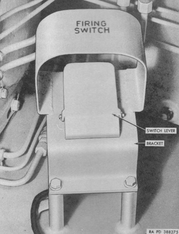
The gunner had a foot trigger to fire the gun electrically. (Picture from TM 9-2350-210-12 Operation and Organizational Maintenance 155-mm Self-propelled Gun Cannon M52 (T97) and 8-inch Self-propelled Howitzer Cannon M55 (T108).)
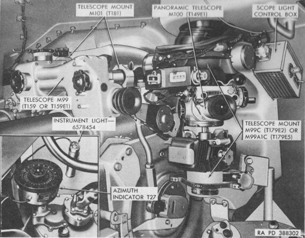
This image presents an overview of the gunner's sighting and fire control instruments. (Picture from TM 9-2350-210-12 Operation and Organizational Maintenance 155-mm Self-propelled Gun Cannon M52 (T97) and 8-inch Self-propelled Howitzer Cannon M55 (T108).)
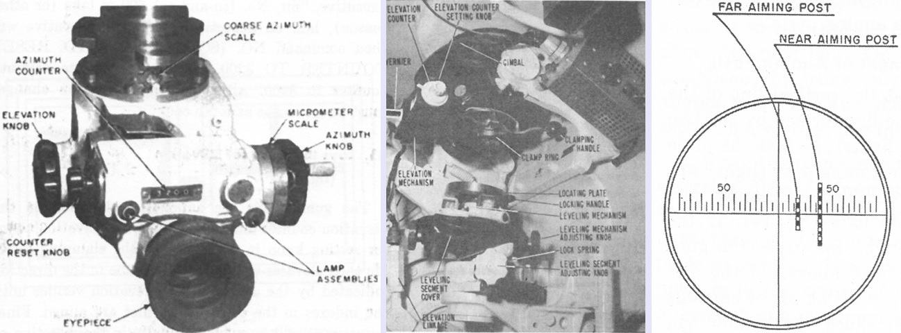
The panoramic telescope M100 is shown on the left. In the center is its telescope mount M99C (T179E2). On the right is its reticle pattern, which is depicted showing a left deflection using two aiming posts. The reticle consisted of a vertical line and a horizontal line that was graduated in 5-mil intervals and numbered in 50-mil intervals. (Picture from FM 6-93 155-mm Gun M53, Self-propelled and 8-inch Howitzer M55, Self-propelled.)
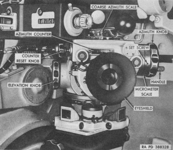
Another view of the mounted panoramic telescope M100 is provided above. Used for indirect fire, it was a 4x device with a 10° field of view and could be adjusted in elevation from -300 to +300 mils. (Picture from TM 9-2350-210-12 Operation and Organizational Maintenance 155-mm Self-propelled Gun Cannon M52 (T97) and 8-inch Self-propelled Howitzer Cannon M55 (T108).)
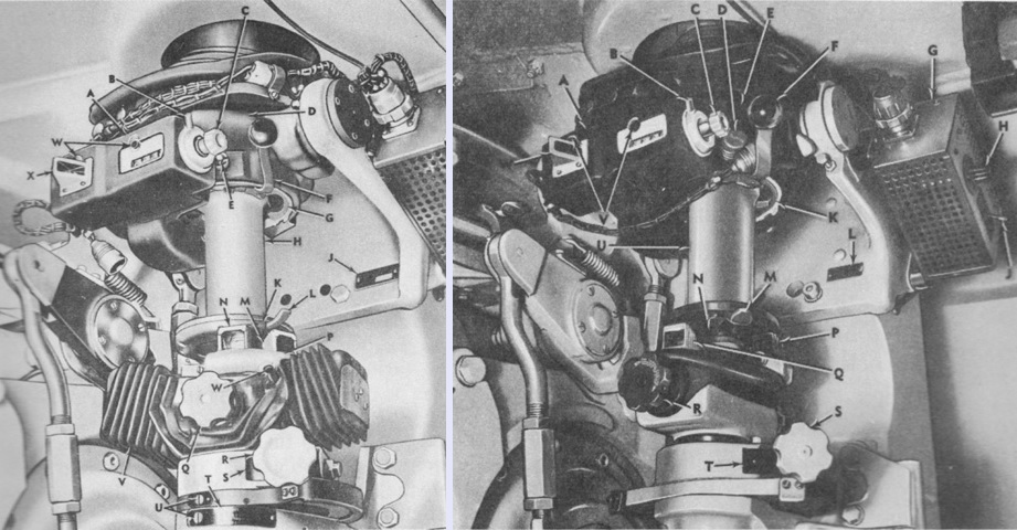
The panoramic telescope M100 could be installed in either the telescope mount M99C (T179E2), as seen on the left, or the M99A1C (T179E5), shown on the right. Differences between the two were minor and were principally concerned with how to install and remove the telescope. Both were azimuth-compensating types, which when cross and longitudinally leveled, corrected for azimuth errors caused by elevating the ordnance with the trunnions canted. The legend for the left image is: A. Elevation counter. B. Clamping handle. C. Elevation counter setting knob. D. Gimbal. E. Clamp ring locking plunger. F. Clamp ring locking handle. G. Clamp ring. H. Travel insert. J. Name plate. K. Locating plate. L. Locating plate locking handle. M. Leveling segment level vial prism. N. Leveling mechanism level vial prism. P. Leveling mechanism. Q. Leveling mechanism adjusting knob. R. Leveling segment adjusting knob. S. Lock spring. T. Instruction plate. U. Locating dots. V. Leveling segment cover. W. Lamp assemblies. X. Elevation vernier window.
The legend for the right image is: A. Elevation counter. B. Clamping handle. C. Elevation counter setting knob. D. Clamp ring locking plunger. E. Gimbal. F. Clamp ring locking handle. G. Light control box. H. Rheostat control knob. J. Light switch lever. K. Clamp ring. L. Name plate. M. Locating plate locking handle. N. Locating plate. P. Leveling segment level vial prism. Q. Leveling mechanism level vial prism. R. Leveling mechanism adjusting knob. S. Leveling segment adjusting knob. T. Lock spring. U. Travel insert. V. Lamp assemblies. W. Elevation vernier window. (Picture from TM 9-2350-210-12 Operation and Organizational Maintenance 155-mm Self-propelled Gun Cannon M52 (T97) and 8-inch Self-propelled Howitzer Cannon M55 (T108).)
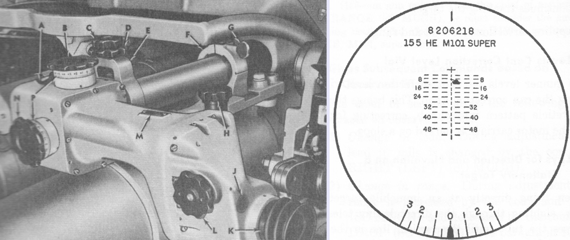
The telescope M99 (T159/T159E1) was a 4x elbow-type device with a 10° field of view. Used for direct fire, it was secured in the telescope mount M101 (T181) directly to the right of the recoil cylinder replenishers. A. Boresight knob locking lever. B. Elevation boresight knob. C. Mount clamping knob. D. Mount locking knob. E. Rear clamp assembly. F. Front clamp assembly. G. Mount clamping screw. H. Telescope locking knob. J. Cant correction level vial window. K. Eyeshield. L. Cant correction knob. M. Name plate. N. Azimuth boresight knob. P. Micrometer scale.
The reticle pattern of the telescope M99 is drawn on the right. The cross represented zero range and deflection and was used during boresighting. The vertical range line was numbered in hundreds of yards, and each line and space of the broken horizontal lines represented a deflection of 5 mils. The gunner above is depicted engaging a tank at 1,200 yards (1,100m) with a 5 mil lead. (Pictures from TM 9-2350-210-12 Operation and Organizational Maintenance 155-mm Self-propelled Gun Cannon M52 (T97) and 8-inch Self-propelled Howitzer Cannon M55 (T108) and FM 6-93 155-mm Gun M53, Self-propelled and 8-inch Howitzer M55, Self-propelled.)
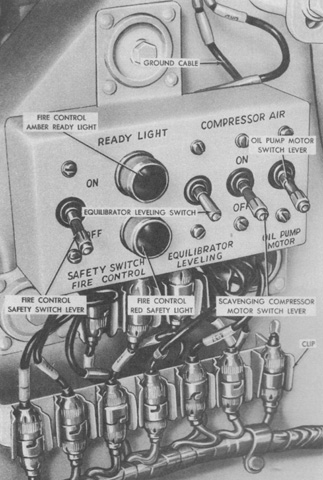
The fire control box contained the ordnance safety switch, equilibrator leveling switch, scavenging compressor motor switch, and oil pump motor switch. When in the off position, the fire control safety switch broke the gun's electrical firing circuit, ensuring that it could not be discharged. The red fire control safety light would illuminate whenever the switch was in the on position. The amber fire control ready light illuminated whenever the loader pressed his safety switch after loading was completed and the firing circuit was energized. The equilibrator leveling switch was used when manually setting the equilibrator, and energized the slope adjustment control when held in the up position. The scavenging compressor motor switch operated the air compressor motor that charged the scavenging system. The oil pump motor switch operated the elevating and traversing oil pump motor. (Picture from TM 9-2350-210-12 Operation and Organizational Maintenance 155-mm Self-propelled Gun Cannon M52 (T97) and 8-inch Self-propelled Howitzer Cannon M55 (T108).)

Two hydraulically-connected equilibration systems balanced the ordnance on slopes of up to 15°. The gun itself was balanced by the vertical equilibration system, while the horizontal equilibration system balanced the turret. Gas pressure in the system was raised or lowered by pumping or draining oil into or out of the accumulator, inside of which was a rubber bladder along with oil and gas. The vertical equilibrator cylinder was connected to the turret floor and to the equilibrator balancing lever, and gas pressure was supplied to this cylinder from two nitrogen bottles. The vertical adjusting cylinder was attached to the balancing lever and arm, and was connected to the horizontal equilibrator cylinder by a hydraulic line. The horizontal equilibrator cylinder was attached to the turret floor, while the two horizontal adjusting cylinders were secured to the hull floor. The piston rods of these three cylinders were pinned together to form a moveable cylinder junction that rested on a support in the hull floor. When the equilibrator leveling switch on the gunner's fire control box was used, the slope adjustment control was energized and the slope control valves were opened. Oil was released from the right horizontal adjusting cylinder into the left horizontal adjusting cylinder, which moved the cylinder junction forward and to the right a distance proportional to the slope upon which the vehicle rested. This extended the piston rod of the horizontal equilibrator cylinder, which forced oil into the vertical adjusting cylinder. As the piston rod of the vertical equilibrator cylinder extended, gas pressure in the system was increased and the gun was brought into balance. A cable connecting the cylinder junction pin to the slope adjustment control worked to level the four slope-sensitive mercury switches in the slope adjustment control, which closed the valves and locked the horizontal adjusting cylinders in position. Turret rotation would then move the horizontal equilibrator piston rod in or out, which would displace oil into the vertical adjusting cylinder to adjust the gun for pitch; and also would develop torque about the turret center of rotation equal and opposite to the turret's tendency to swing downhill. The equilibration system is diagrammed schematically on the left, and a flow diagram is drawn on the right. Normal gas pressure was 1,240psi (87.2kg/cm²), and normal oil pressure was 2,000psi (141kg/cm²). (Pictures from TM 9-2350-210-12 Operation and Organizational Maintenance 155-mm Self-propelled Gun Cannon M52 (T97) and 8-inch Self-propelled Howitzer Cannon M55 (T108).)
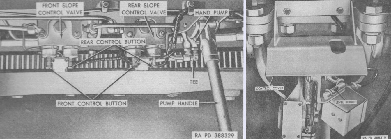
The two equilibrator slope control valves and hand pump are shown on the left. The solenoid-controlled valves, used to set manually set the equilibrator system, were below the lower right edge of the turret ring. The front valve was connected to the right horizontal adjusting cylinder, while the rear valve was connected to the left horizontal adjusting cylinder. The valves had front and rear control buttons: the front buttons caused the piston rods to move out, while the rear buttons retracted the piston rods. The hand pump was used to supply hydraulic pressure to the equilibration system in the case of failure of the hydraulic pump unit. When not in use, the pump handle was stowed on the wall of the turret support compartment. The right image illustrates the slope adjustment control that automatically set the equilibration system. When setting the system manually, two level bubbles were provided on the control to aid the operator. (Picture from TM 9-2350-210-12 Operation and Organizational Maintenance 155-mm Self-propelled Gun Cannon M52 (T97) and 8-inch Self-propelled Howitzer Cannon M55 (T108).)
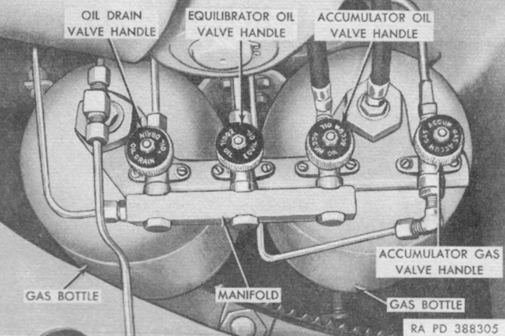
Four handles to the right of the driver's seat could be used to actuate shutoff valves in the equilibration system to isolate different portions. The oil drain valve permitted oil to drain from the vertical and horizontal equilibration systems; the equilibrator oil valve isolated the circuit connecting the horizontal equilibrator cylinder to the vertical adjusting cylinder; the accumulator oil valve allowed oil to be pumped into or drained from the accumulator; and the accumulator gas valve controlled the flow of gas into the accumulator. (Picture from TM 9-2350-210-12 Operation and Organizational Maintenance 155-mm Self-propelled Gun Cannon M52 (T97) and 8-inch Self-propelled Howitzer Cannon M55 (T108).)
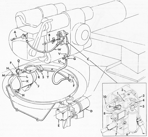
Smoke and gas were ejected from the firing chamber after the gun was fired by the scavenging system. The air compressor filled the reservoir up to a pressure of 95psi (6.7kg/cm²). The breech air port supply line was made of two sections: a forward section mounted on the gun cradle and a rear section on the breech ring, which remained stationary when the gun was fired. When the breechblock was opened, a cam in the breech tripped the timer control rod, which activated the pneumatic timer for ~2 seconds. As this happened, a pressure switch would restart compressor motor. A shutoff valve plug on the timer enabled the system to be shut off while, for example, examining for misfire.
A. Breech air port supply pipe. B. Control rod. C. Scavenging pneumatic timer. 1. Pilot valve. 2. Flow control valve. 3. Flow control valve tube. 4. Timer air supply valve. 5. Pilot valve tube. 6. Air chamber. 7. Master valve. 8. Air release valve. 9. Shutoff plug valve. 10. Air release valve tube. D. Compressor motor. E. Compressor. F. Turret air supply connector block coupling. G. Timer tube elbow connector block. H. Reservoir drain cock. J. Reservoir. K. Mounting strap. L. ⅜ x 5 in. (.953cm x 13cm) hex-head cap screw. M. ⅜ in. (.953cm) lock washer. N. ⅜ in. (.953cm) hex nut. P. Pressure gage. Q. Relief valve. R. Pressure switch air tube. S. Pressure switch. T. Turret air supply connector block coupling tube. U. Timer tube elbow connector block hose. V. Timer tube. W. Discharge tube. (Pictures from TM 9-2350-210-12 Operation and Organizational Maintenance 155-mm Self-propelled Gun Cannon M52 (T97) and 8-inch Self-propelled Howitzer Cannon M55 (T108).)
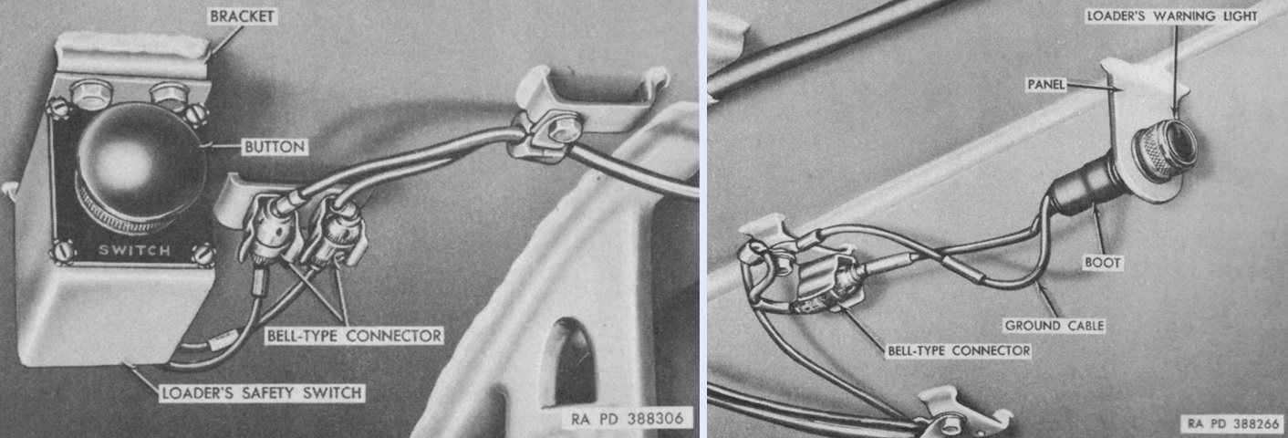
After loading was complete, the loader pressed his safety switch button, which energized the firing circuit and lit warning lamps at the loader's station and on the gunner's fire control box. (Picture from TM 9-2350-210-12 Operation and Organizational Maintenance 155-mm Self-propelled Gun Cannon M52 (T97) and 8-inch Self-propelled Howitzer Cannon M55 (T108).)
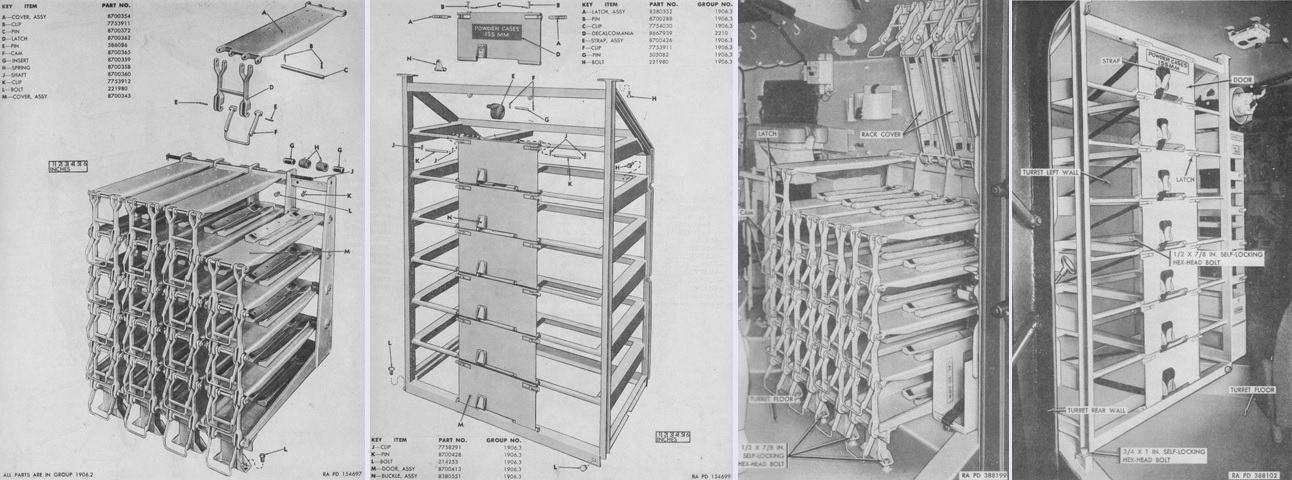
The 155mm projectile and powder case racks are isolated in the left two images, respectively, and seen installed in the two right images. (Pictures from ORD 9 SNL G-259 List of All Service Parts of Gun, Self-propelled, Full Tracked: 155-mm, T97 and Howitzer, Self-propelled, Full Tracked: 8-in, T108 and TM 9-2350-210-12 Operation and Organizational Maintenance 155-mm Self-propelled Gun Cannon M52 (T97) and 8-inch Self-propelled Howitzer Cannon M55 (T108).)
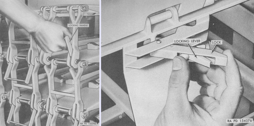
The controls for the 155mm projectile and powder case racks are illustrated on the left and right, respectively. Projectiles were secured with lifting locking handles, while the cover of each tier of the powder case rack was locked with two squeezable levers. Canvas straps further secured the powder cases inside the rack. (Picture from TM 9-2350-210-12 Operation and Organizational Maintenance 155-mm Self-propelled Gun Cannon M52 (T97) and 8-inch Self-propelled Howitzer Cannon M55 (T108).)
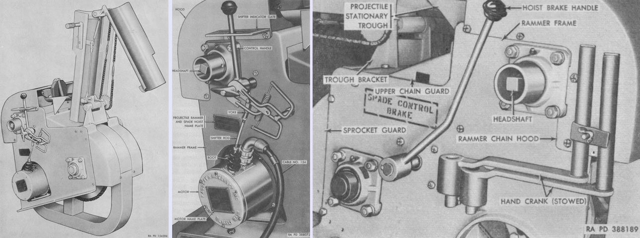
The electric projectile rammer and spade hoist is shown isolated on the left, while a right-side view is in the center, and a left-rear view is on the right. The spring-loaded control handle in the center image was moved to different sections of the shifter gate in order to select spade HOIST, projectile RAM, or rammer RETRACT operations, and automatically returned to the neutral OFF position when released. A headshaft safety clutch sprocket prevented the motor from stalling when the projectile was seated in the firing chamber or when the spade was hoisted into its securing latches. The handcranks stowed in the right image were used to operate the rammer and spade hoist if the power failed. They were slipped over the ends of the headshaft when needed. The spring-loaded hoist brake handle released the brake that controlled the descent of the rear spade. The brake was normally always on unless released by the handle. (Pictures from ORD 9 SNL G-259 List of All Service Parts of Gun, Self-propelled, Full Tracked: 155-mm, T97 and Howitzer, Self-propelled, Full Tracked: 8-in, T108 and TM 9-2350-210-12 Operation and Organizational Maintenance 155-mm Self-propelled Gun Cannon M52 (T97) and 8-inch Self-propelled Howitzer Cannon M55 (T108).)
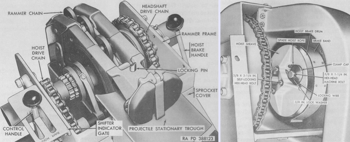
The rammer chain hood has been removed from the rammer and spade hoist in the left image, while the spade hoist sheave has been revealed on the right. The locking pin prevented the rammer chain from moving forward until a projectile was placed on the projectile trough. (Pictures from TM 9-2350-210-12 Operation and Organizational Maintenance 155-mm Self-propelled Gun Cannon M52 (T97) and 8-inch Self-propelled Howitzer Cannon M55 (T108).)
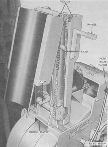
The projectile trough is seen above in the stowed position, and was unfolded into the ramming position by pulling the handle out of the detent in the trough and then pushing it forward. (Pictures from TM 9-2350-210-12 Operation and Organizational Maintenance 155-mm Self-propelled Gun Cannon M52 (T97) and 8-inch Self-propelled Howitzer Cannon M55 (T108).)
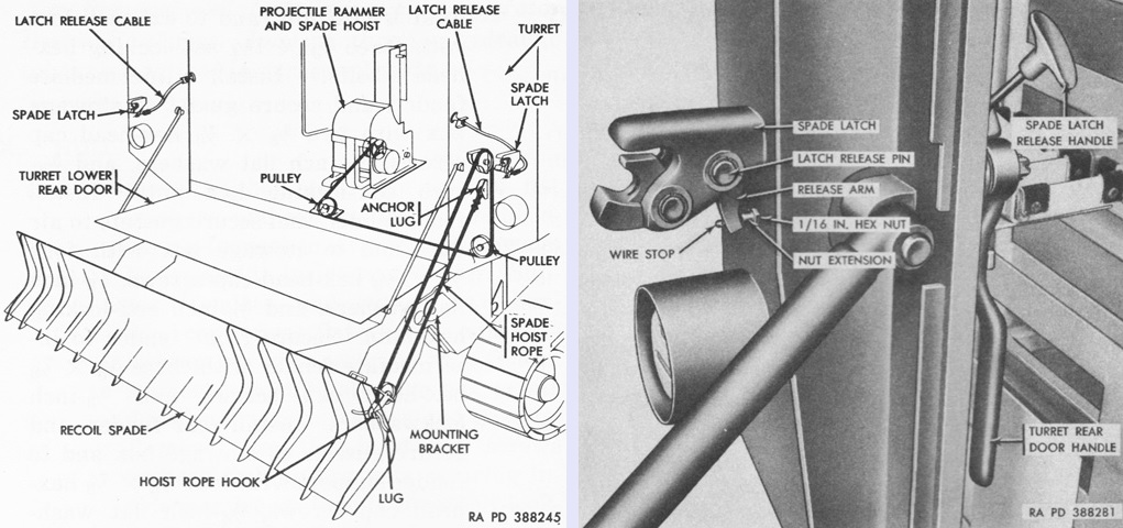
The routing of the spade hoist rope is drawn on the left. A spade latch release handle was found on each side of the turret rear wall as seen on the right. The latches were released by pulling the handles upward, and after the spade was lowered the handles were to be pushed down into the closed position so that the latches would automatically lock when the spade was raised. (Pictures from TM 9-2350-210-12 Operation and Organizational Maintenance 155-mm Self-propelled Gun Cannon M52 (T97) and 8-inch Self-propelled Howitzer Cannon M55 (T108).)
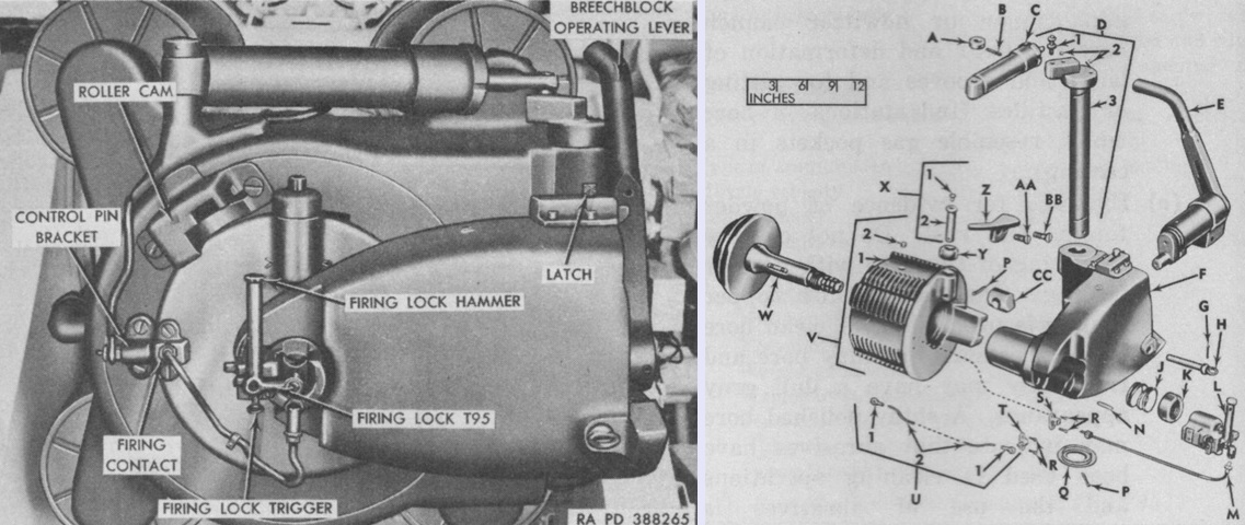
The horizontal-swing, stepped-thread, interrupted-screw breech is seen above, closed on the left and exploded on the right. The breechblock carrier was secured in lugs on the breech ring body by a hinge pin, whose upper end was attached to the piston rod of the breechblock counterbalance. The other end of the counterbalance was mounted on the breech ring body. The legend for the right image is: A. Collar. B. 1/16 x 1½ in. (.159cm x 3.8cm) spring pin. C. Breechblock counterbalance. D. Hinge pin. 1. Pin. 2. Cup. 3. Body. E. Breechblock operating lever. F. Breechblock carrier. G. ⅛ x 2 in. (.318cm x 5.1cm) cotter pin. H. Bearing retaining bolt. J. Obturator spindle spring. K. Spring retaining nut. L. Firing lock T95. M. Firing cable. N. Firing lock stop screw. P. 5/32 x 2¼ in. (.39688cm x 5.72cm) cotter pin. Q. Carrier bearing washer. R. Contact pin bracket screw. S. Contact. T. Contact pin bracket. U. Electric connection. 1. Terminal. 2. Cable. V. Breechblock. 1. Block. 2. Cup. W. Obturator spindle. X. Roller pivot. 1. Cup. 2. Pin. Y. Roller. Z. Breechblock control arc. AA. Arc short screw. BB. Arc long screw. CC. Crosshead. (Pictures from TM 9-2350-210-12 Operation and Organizational Maintenance 155-mm Self-propelled Gun Cannon M52 (T97) and 8-inch Self-propelled Howitzer Cannon M55 (T108).)
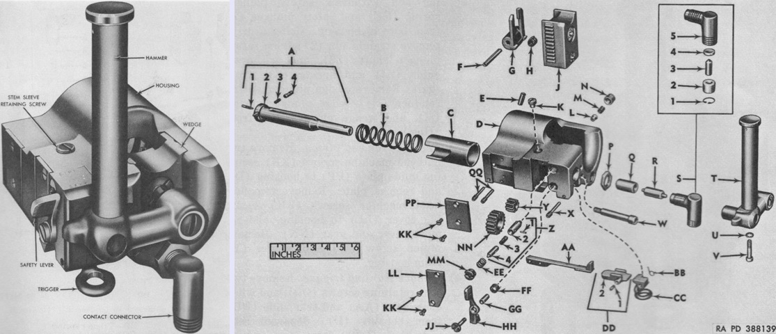
The firing lock T95 could also be found on the 155mm self-propelled howitzer M44. Mounted in the breechblock carrier and projecting past the obturator spindle, it provided for the seating, electrical and mechanical firing, and extraction of the primer. It was to be used electrically unless the power failed, but late-production firing locks were not able to be operated manually. The hammer combined the functions of an operating handle, a percussion hammer, and an electrical conduit.
The legend for the exploded view on the right is: A. Hammer stem. 1. Screw. 2. Shaft. 3. Spring. 4. Plunger. B. Firing spring. C. Stem sleeve. D. Housing. E. 3/16 x ½ spring pin. F. 5/32 x 1⅜ spring pin. G. Primer extractor. H. Extractor spring. J. Wedge. K. Sleeve retaining screw. L. Wedge plunger. M. Wedge plunger spring. N. Wedge plunger spring retainer. P. ½-inch (1.3cm) hex nut. Q. Insulator. R. Contact. S. Contact connector. 1. Retaining ring. 2. Guide. 3. Capsule. 4. Stop. 5. Elbow. T. Hammer. U. No. 8 lockwasher. V. Stem screw. W. Pinion screw. X. Trigger retaining screw. Y. Pinion. Z. Safety plunger. 1. 1/16 x ¼ straight pin. 2. Shaft. 3. Spring. 4. Guide. AA. Sear. BB. Trigger spring. CC. Trigger. DD. Sear slide. 1. Block. 2. Stud. EE. Safety plunger spring. FF. Safety lever return spring. GG. Safety lever pivot sleeve. HH. Safety lever. JJ. Lever pivot. KK. No. 5 x 0.31 flat-head machine screw. LL. Cover. MM. Plunger plug. NN. Gear. PP. Guide plate. QQ. Sear retaining screw. (Pictures from TM 9-2350-210-12 Operation and Organizational Maintenance 155-mm Self-propelled Gun Cannon M52 (T97) and 8-inch Self-propelled Howitzer Cannon M55 (T108).)
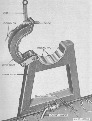
The travel lock was hinged to the front wall of the hull, and was secured in the raised or lowered position by a locking handle that engaged lugs welded to the lower clamp and the hull. The clamps were locked together by a lever-operated screw. (Pictures from TM 9-2350-210-12 Operation and Organizational Maintenance 155-mm Self-propelled Gun Cannon M52 (T97) and 8-inch Self-propelled Howitzer Cannon M55 (T108).)
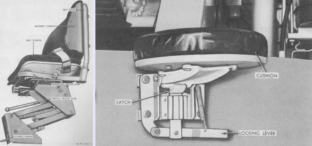
The commander, gunner, and driver were provided with the seats on the left, while the three cannoneers had seats in the turret as seen on the right. The turret seats could fold down out of the way when not in use. (Pictures from TM 9-2350-210-12 Operation and Organizational Maintenance 155-mm Self-propelled Gun Cannon M52 (T97) and 8-inch Self-propelled Howitzer Cannon M55 (T108).)
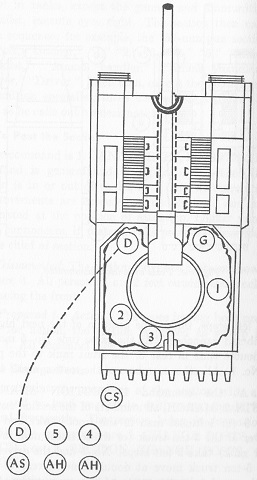
Minus the driver of the accompanying 5-ton truck, the crew of the entire gun section are shown here ready for action. The abbreviations are as follows: D: Driver. G: Gunner. CS: Chief of section. AS: Ammunition specialist. AH: Ammunition handler. The numbered crewmen are cannoneers. Cannoneer number 1 is also the assistant gunner. (Picture from FM 6-93 155-mm Gun M53, Self-propelled and 8-inch Howitzer M55, Self-propelled.)
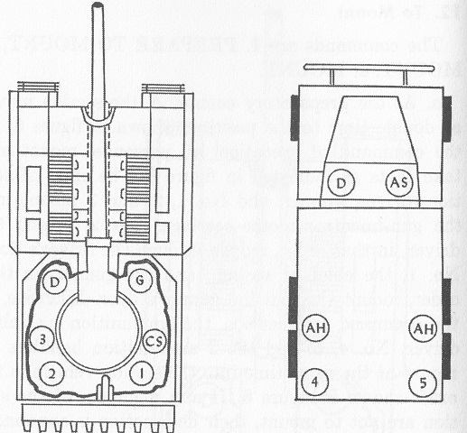
The crew of the gun section are shown mounted in this image. Six men rode in the self-propelled gun, leaving 6 in the truck. (Picture from FM 6-93 155-mm Gun M53, Self-propelled and 8-inch Howitzer M55, Self-propelled.)