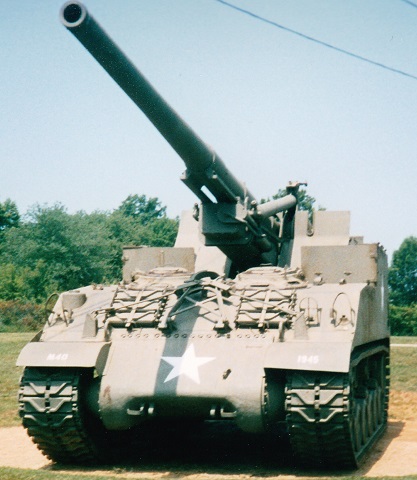
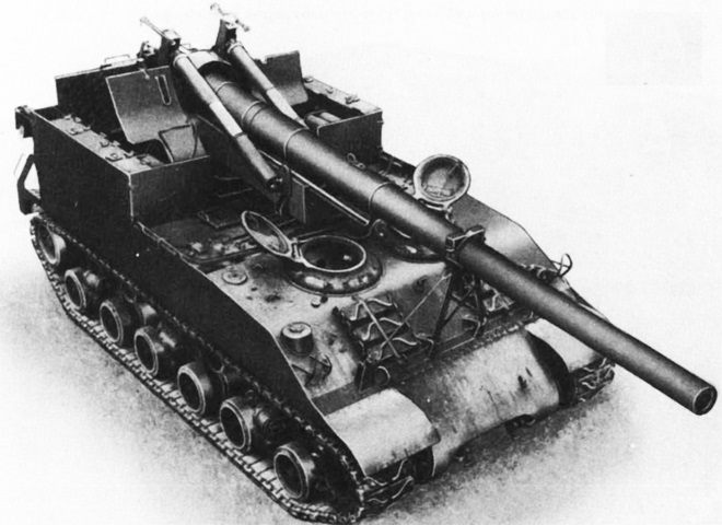
155mm Gun Motor Carriage M40 at the Patton Museum of Cavalry and Armor.
The 155mm GMC M40 used the HVS suspension system, and spare track blocks for the T84 tracks are stowed on the hull front on each side of the gun travel lock. The drivers' cupolas can be seen above the spare track. The late-production Sherman features include the single-piece, sharp-nosed final drive and differential cover. Although the vehicle is wider than the Sherman tank, note that the final drive and differential cover is the same, leaving a space between it and the tracks.
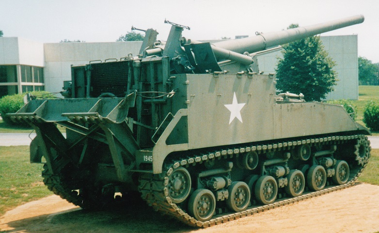
This rear view shows the stowed position of the large stabilizing spade that steadied the vehicle during bombardment. A working platform for the gun crew is folded up behind the spade; this came down over top of the spade when the vehicle was ready to fire.
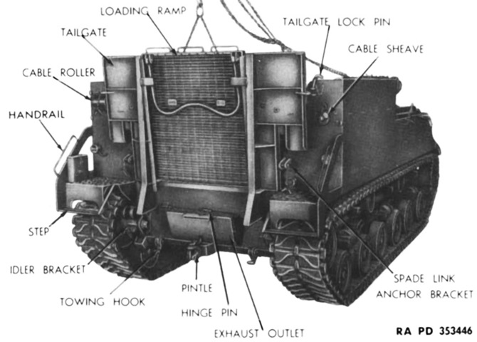
The stowed platform and hull rear are more easily seen with the spade removed. The loading ramp is chained from above in preparation for its disassembly from the carriage. (Picture from TM 9-1747.)
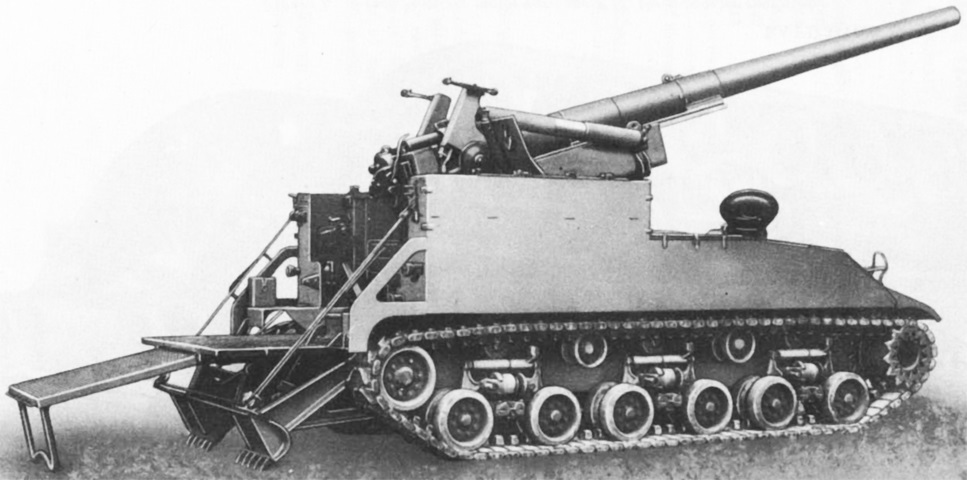
A similar angle displays the spade and platform deployed for firing. (Picture from TM 9-1747.)
The mid-mounted engine compartment was placed between the rear ordnance and the drivers in front. (Picture from TM 9-1747.)
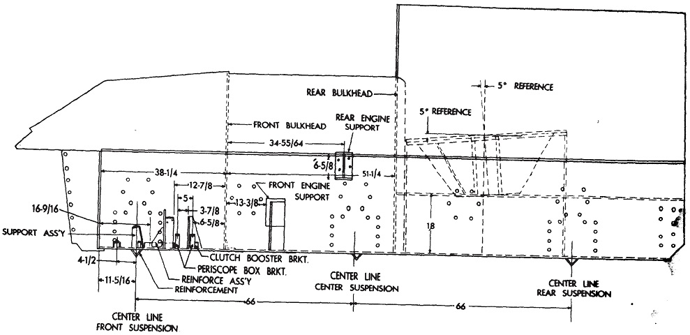
A cross-section of the hull is shown here. Note the holes for the bolts to attach the final drive and differential housing; these are angled forward to make up for the steeper slope of the propeller shaft engendered by moving the engine forward. The gun mount was also installed at a 5° forward cant. (Picture from TM 9-747 Feb 1945.)
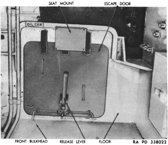
An escape hatch was found in the hull floor behind the assistant driver. (Picture from TM 9-1747.)
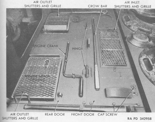
The engine doors, grilles, and stowage are shown here with the vehicle facing to the right. (Picture from TM 9-747 Sep 1947.)
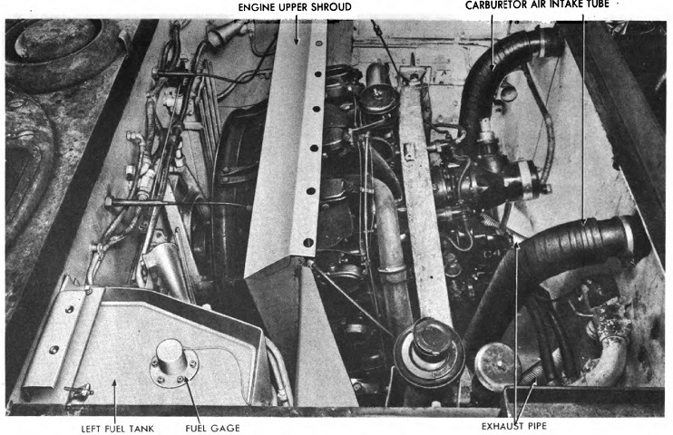
The engine is shown here installed. The vehicle is facing to the left, and the rear of the driver's cupola and the ventilating blower situated between the drivers can be seen on the left of the image. (Picture from TM 9-747 Feb 1945.)
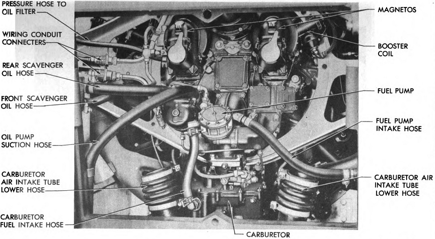
The rear of the installed engine is detailed in this picture. (Picture from TM 9-747 Feb 1945.)
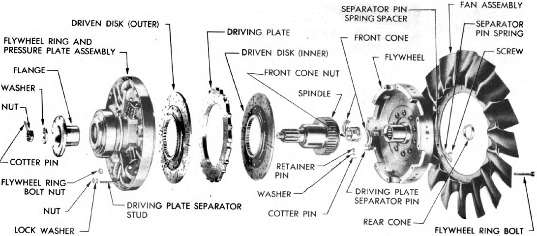
An exploded view of the engine's clutch and fan assemblies is shown here. (Picture from TM 9-747 Feb 1945.)
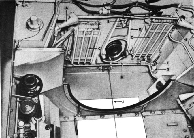
The front bulkhead of the engine compartment is labeled with the powerplant removed. A. Fire extinguisher nozzles. B. Clutch throw-out bracket equalizer ring. C. Oil cooler shutter. D. Clutch throw-out yoke. E. Fuel shut-off valve control. F. Fuel shut-off valve. G. Fuel filter. H. Clutch throw-out bracket tie rod. J. Accelerator rod. (Picture from TM 9-747 Feb 1945.)
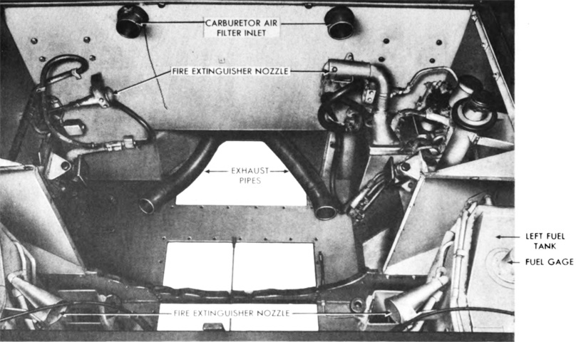
The opposite end of the engine compartment is shown here. (Picture from TM 9-747 Feb 1945.)
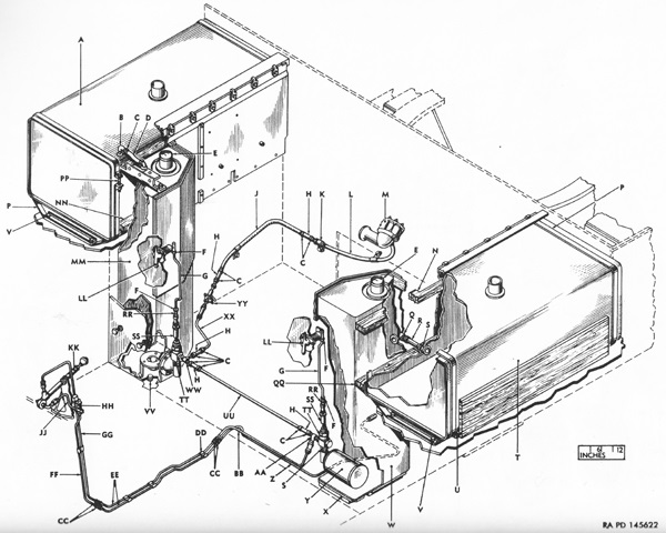
The layout of the fuel system is diagrammed in this sketch. A vertical fuel tank was installed in each front corner of the engine compartment, and a horizontal tank was found in each sponson beside the engine compartment. A. Tank, assy. B. Elbow. C. Clamp. D. Hose. E. Unit. F. Nut. G. Rod. H. Hose. J. Tube. K. Block. L. Hose. M. Pump, assy. N. Spacer. P. Strap. Q. Elbow. R. Hose. S. Nipple. T. Tank, assy. U. Spacer, assy. V. Bolt. W. Tank, assy. X. Spacer, assy. Y. Filter, assy. Z. Tube. AA. Tee. BB. Tube. CC. Union. DD. Clip. EE. Tube. FF. Tube. GG. Tube. HH. Strainer, assy. JJ. Tube. KK. Pump, assy. LL. Control, assy. MM. Tank, assy. NN. Spacer. PP. Screw. QQ. Spacer. RR. End. SS. Absorber, assy. TT. Valve. UU. Tube. VV. Plug. WW. Tee. XX. Tube. YY. Block. (Picture from ORD 9 SNL G-232.)
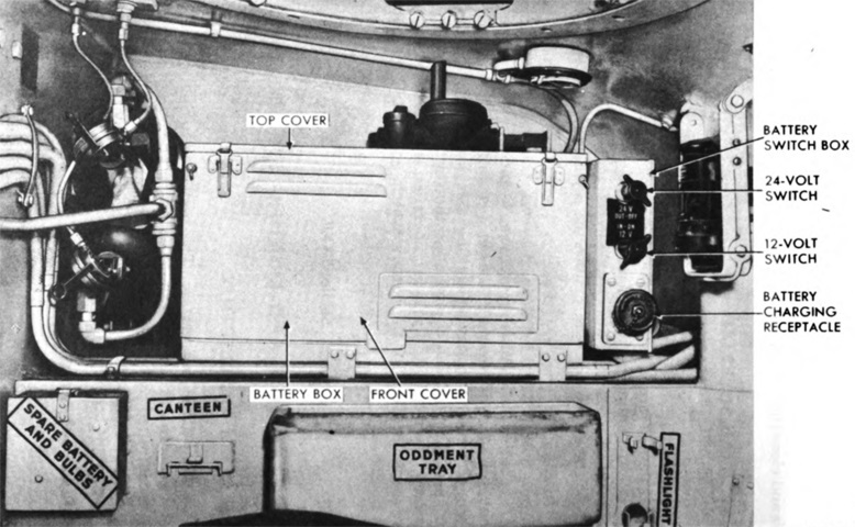
Two 12-volt lead-acid batteries were stored in a box in the left sponson. They were connected in series with the 24-volt switch on the battery box, and a radio circuit was powered by a separate lead from one battery to the 12-volt switch on the battery box. (Picture from TM 9-747 Feb 1945.)
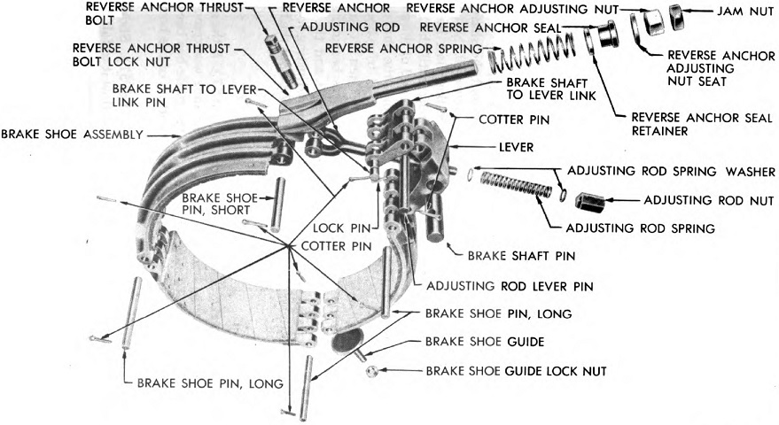
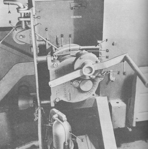
Parts of a steering brake are labeled in this image. (Picture from TM 9-747 Feb 1945.)
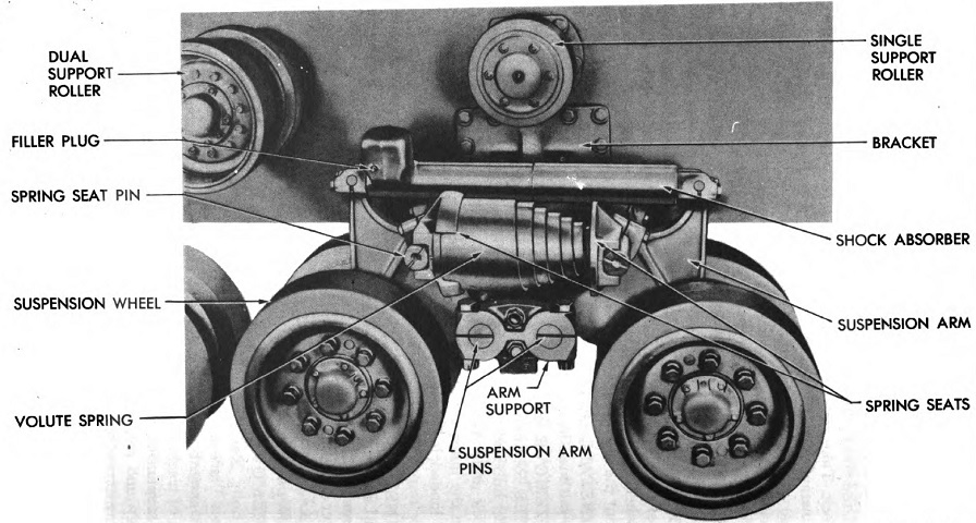
A horizontal volute suspension spring bogie and the different types of return roller are diagrammed here. The road wheels were 20.5" (52.1cm) in diameter, while the dual and single support rollers were 13.5" (34.3cm) and 10" (25cm), respectively. The normal free height of the volute springs was 14" (36cm), but once assembled they were reduced to ~10" (~25cm). The springs had five active coils each, and their maximum outside diameter was 8" (20cm). (Picture from TM 9-747 Feb 1945.)
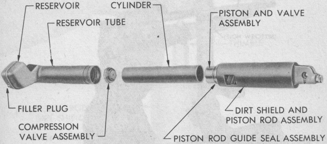
A shock absorber is exploded in this image. (Picture from TM 9-1747.)
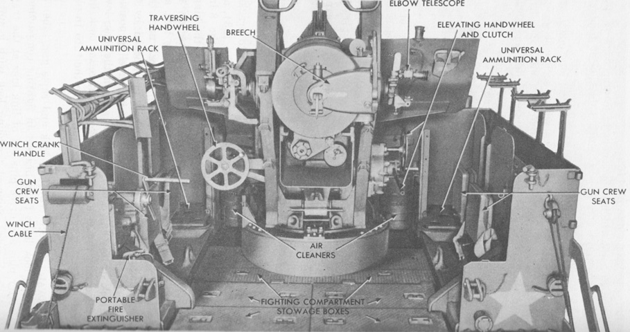
An overview of the fighting compartment is provided here. (Picture from TM 9-747 Sep 1947.)
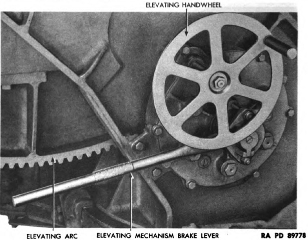
The elevation handwheel on the right side of the cradle and the elevation brake lever are highlighted here. (Picture from TM 9-747 Feb 1945.)
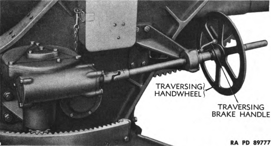
The traversing handwheel on the left side of the cradle and the traversing brake lever are shown here. The traversing brake handle was released by rotating it counterclockwise. (Picture from TM 9-747 Feb 1945.)
The breech of the 155mm gun M2 is shown here. The weight of the complete weapon was 9,595lb (4,352kg), the tube was 277.37" (704.52cm) long, and it could fire a high-explosive shell 25,715 yards (23,513m). (Picture from TM 9-747 Sep 1947.)
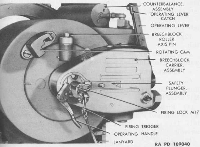
The firing mechanism is diagrammed in this picture. A primer was inserted into the breechblock under the firing mechanism, the percussion hammer locking pin was released, and a sharp pull of the lanyard sent the percussion hammer into the firing pin, igniting the primer and firing the ordnance. (Picture from TM 9-747 Feb 1945.)
The winch for the rear ramp is shown installed on the left and exploded on the right. The legend for the left image is: A. Ramp lock pin. B. Sheave. C. Cable. D. Drum. E. Brake band. F. Brake lever. G. Spring-loaded lock pin. H. Pinion gear housing. J. Ratchet. K. Crank. L. Portable fire extinguisher. (Picture from TM 9-747 Sep 1947 and TM 9-1747.)
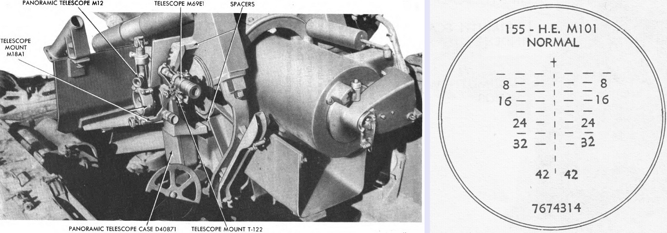
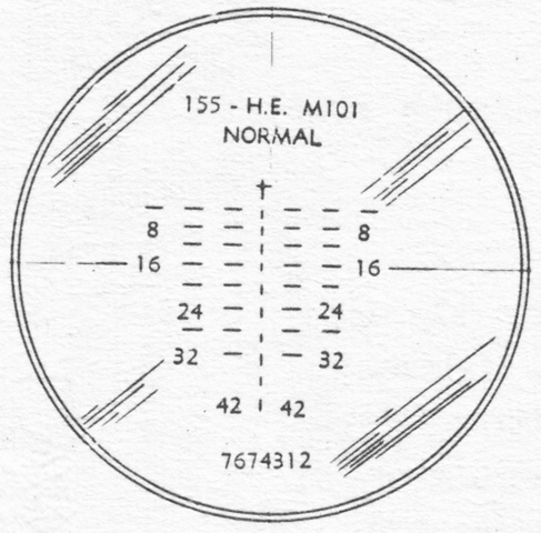
The sights for the 155mm GMC M40 and 8" HMC M43 were the same except for the direct-firing telescopes, which featured different internal reticles for their respective ordnances. The reticle pattern for the telescope M69F is sketched on the right. (Picture from TM 9-747 Feb 1945 and TM 9-747 Sep 1947.)
Similarly, the reticle for the elbow telescope M16A1F is seen above. It was a 3x device with a 13°20' field of view and was used as part of a two-sight, two-man system. (Picture from TM 9-2300 Artillery Matériel and Associated Equipment.)
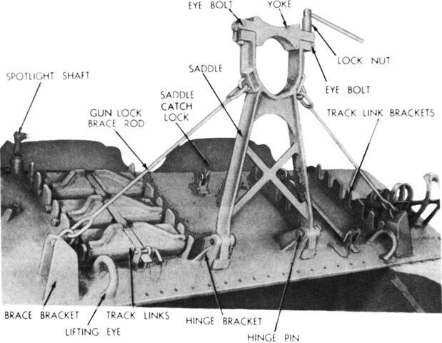
The travel lock on the front hull featured a reversible yoke that could accommodate either the 155mm gun or the 8" howitzer found on the HMC M43. The carriage's differential cover has been removed in this picture. (Picture from TM 9-1747.)
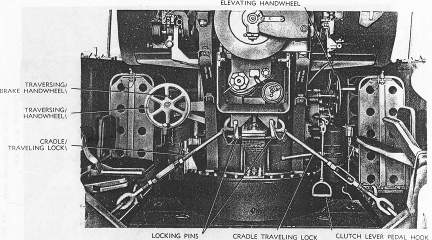
The gun cradle was provided with a traveling lock in addition to that found on the gun tube. The clutch lever pedal hook allowed the crew to release the brake which locked the elevating mechanism. Ammunition racks can be seen at the front corners of the fighting compartment. (Picture from TM 9-747 Sep 1947.)
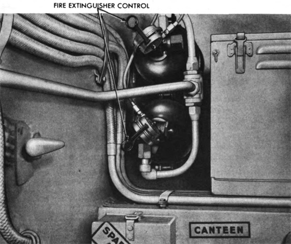
The two cylinders of the fixed fire extinguisher system were mounted just behind the battery box on the left sponson. These could be activated in case of an engine fire by turning the handles on the cylinders' control heads or by pulling the handles on the hull roof to the left rear of the driver's cupola. In addition, two 4lb (1.8kg) portable extinguishers were carried, one each in the driving and fighting compartments. (Picture from TM 9-747 Feb 1945.)
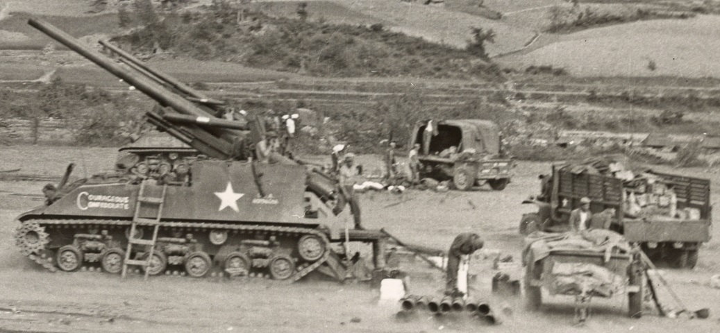
The ordnance on "Courageous Confederate" is shown in recoil just after firing a round against Chinese forces during the Korean War. The spade has dug itself into the ground, and the utility of the loading platform is apparent. These men were from the 937th Field Artillery Battalion of the Arkansas National Guard. (Picture by Cpl Lew Gibson; available from the National Archives.)
