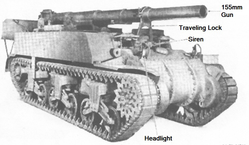
155mm Gun Motor Carriage M12.
The relation of the M12 to the medium tank M3 is apparent when one sees the suspension and the three-piece final drive and differential housing. (Picture from TM 9-751 155-mm Gun Motor Carriage M12 and Cargo Carrier M30.)
The travel lock is raised on this vehicle, but the ordnance is not stowed in it.
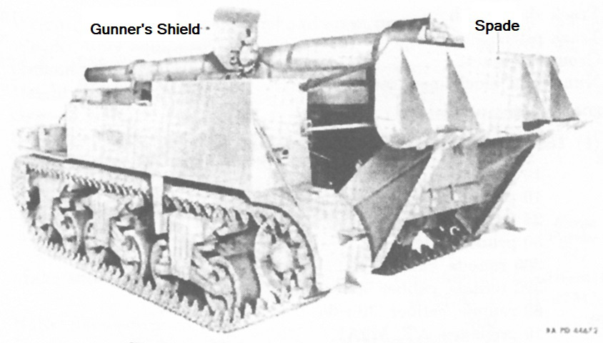
A ventilator is placed on the front of the vehicle between the drivers' hatches, and the siren would normally be mounted directly behind this ventilator. The right-hand headlight is also missing. The gunner's position was to the gun's left, and his shield can be seen towards the rear of the gun.
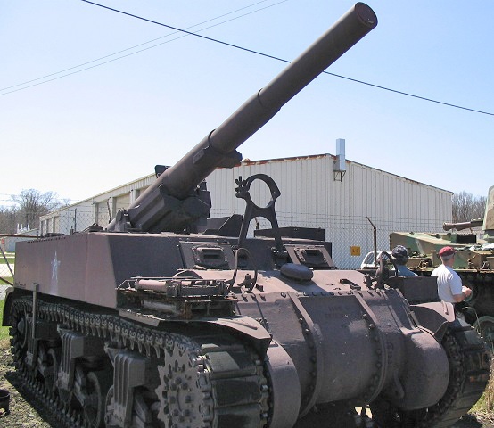
The drivers were provided with top-hinged hatches that opened upwards, and these had direct vision slots in them. A closer look at the gun travel lock, ventilator, and headlight mounts can be seen here. Track spades are stowed on the right front fender; these were placed in front of the tracks when the vehicle was ready to fire.
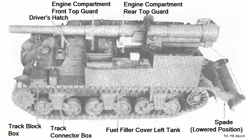
The carriage's engine was moved from the rear in the medium tank to just behind the drivers' compartment, leaving the back of the vehicle free for the gun mount. (Picture from TM 9-751 155-mm Gun Motor Carriage M12 and Cargo Carrier M30.)
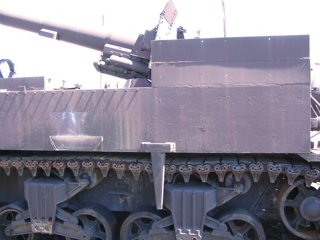
Seats for two crewmen were mounted on the left rear corner of the vehicle, and their position is revealed by the vertical extension to the hull side. This vehicle is equipped with the heavy-duty suspension bogies, and the repositioned engine's exhaust was rerouted to exit between the center and rear bogies on each side.
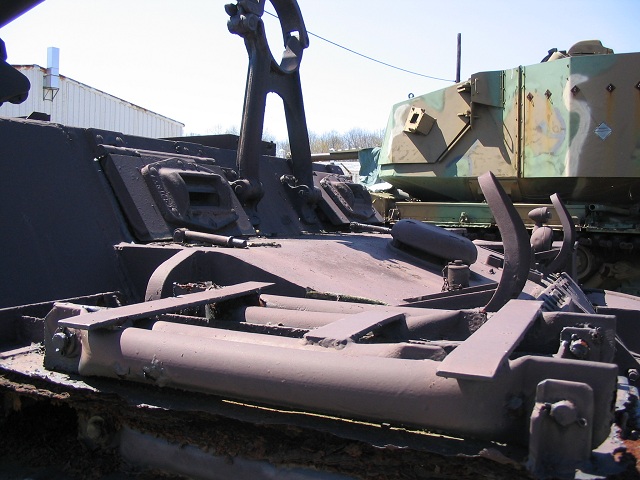
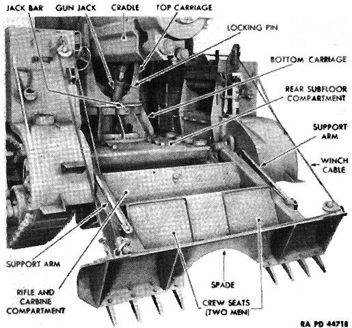
The crew seats mentioned above can better be seen in this top-down view. (Picture from TM 9-751 155-mm Gun Motor Carriage M12 and Cargo Carrier M30.)
The recoil spade is shown here in the stowed position. (Picture from TM 9-751 155-mm Gun Motor Carriage M12 and Cargo Carrier M30.)
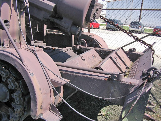
The vehicle's spade would normally be retracted to a more vertical position as shown above. Seating for two more crewmen was provided on the spade itself.
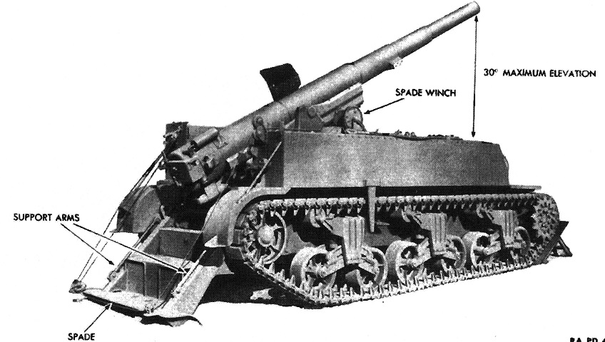
The vehicle is shown ready to fire, with the rear spade deployed and the track spades in front of the tracks. (Picture from TM 9-751 155-mm Gun Motor Carriage M12 and Cargo Carrier M30.)
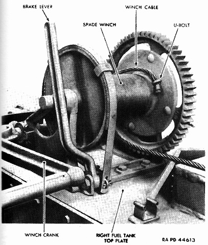
Details of the rear spade winch are shown here. The spade was lowered with the brake lever once the support arms had been released, then raised using the winch crank when the vehicle was prepared to move. After the winch was lowered, the vehicle was to be reversed until the prongs were forced into the ground. The steps on the spade were horizontal when it was properly emplaced. (Picture from TM 9-751 155-mm Gun Motor Carriage M12 and Cargo Carrier M30.)
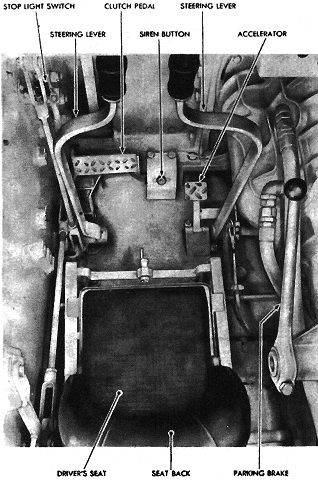
The driver's controls are shown here. As can be imagined, operating the M12 was similar to driving the medium tank on which it was based. (Picture from TM 9-751 155-mm Gun Motor Carriage M12 and Cargo Carrier M30.)
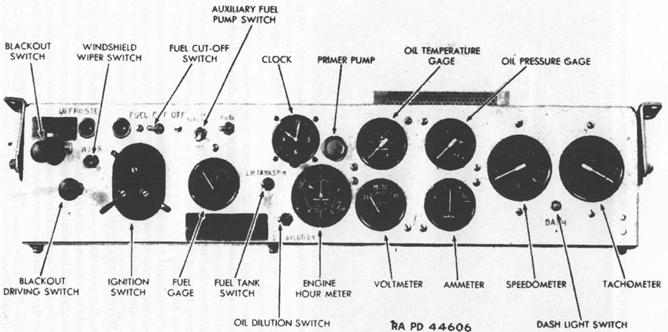
The driver's instrument panel is labeled in this image. (Picture from TM 9-751 155-mm Gun Motor Carriage M12 and Cargo Carrier M30.)
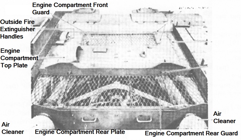
The engine compartment covers and guards are shown here, looking forward from the rear compartment. The drivers' hatches can be seen at the top of the image. (Picture from TM 9-751 155-mm Gun Motor Carriage M12 and Cargo Carrier M30.)
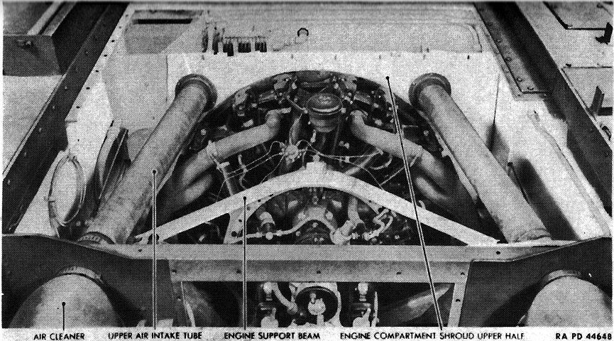
The engine covers have been removed in this image, revealing the radial engine. The front of the vehicle is again to the top of the image. (Picture from TM 9-751 155-mm Gun Motor Carriage M12 and Cargo Carrier M30.)

With the right fuel tank top plate removed, the tank itself is visible. The near fuel tank hangers are bent up and away from the fuel tank in preparation for the tank's removal. A similar fuel tank was installed in the opposite sponson. (Picture from TM 9-751 155-mm Gun Motor Carriage M12 and Cargo Carrier M30.)
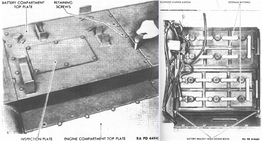
Two 12-volt storage batteries were connected in series to maintain the electrical system at 24 volts. The battery compartment was in the right sponson between the sponson box and the fuel tank. (Picture from TM 9-751 155-mm Gun Motor Carriage M12 and Cargo Carrier M30.)
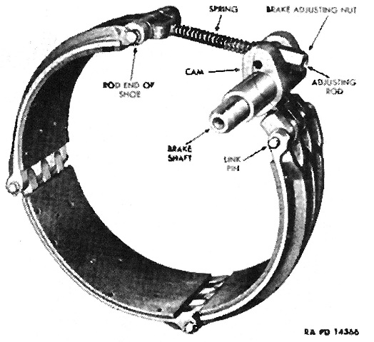
Details of one of the steering brake bands are shown here. (Picture from TM 9-751 155-mm Gun Motor Carriage M12 and Cargo Carrier M30.)
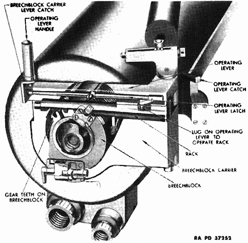
This phantom view shows interior details of the gun breech. The gun's maximum horizontal range was ~20,000yd (~18,000m). The complete gun weighed 8,715lb (3953kg) and had a length from the muzzle to the rear face of the breech ring of 232.87" (291.49cm). (Picture from TM 9-751 155-mm Gun Motor Carriage M12 and Cargo Carrier M30.)
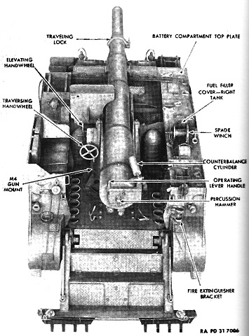
Details of the gun mount M4 can be seen in this image. The engine air cleaners were mounted at the front of the fighting compartment near the repositioned engine, and stowage for ten 155mm rounds was provided in the fighting compartment. Four projectiles were stowed in the floor on the right side of the compartment, and the location of some of these can be seen here.
Further details of the gun mount and rear stowage are shown here. The gun mount was designed to give the vehicle the lowest center of gravity possible. (Picture from TM 9-751 155-mm Gun Motor Carriage M12 and Cargo Carrier M30.)
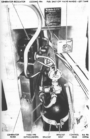
The fixed fire extinguisher system consisted of two 10lb (4.5kg) CO2 cylinders mounted in the recessed compartment behind the driver's seat. They were routed to the engine compartment to suffocate fires there. Two 4lb (1.8kg) portable fire extinguishers were also carried, one on either side of the crew compartment. (Picture from TM 9-751 155-mm Gun Motor Carriage M12 and Cargo Carrier M30.)
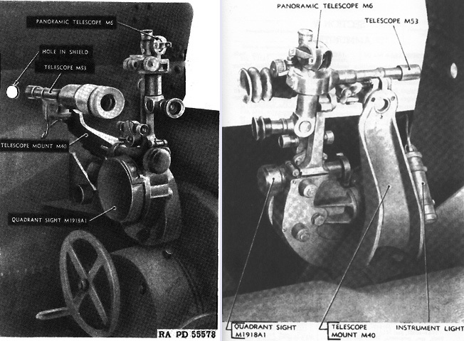
The sighting equipment is seen above from the left rear and right rear in the left and right images, respectively. The telescope M53 was used to place the gun in azimuth and elevation in direct fire against fast-moving targets. It was an adaptation of the elbow telescope M6 into a straight, lens-erecting telescope. The M53A1 was a 3x device with a 10°27' field of view, and its antitank-pattern reticle was calibrated with the supercharge 155mm HE shell M101 with 2,410 ft/sec (735m/s) muzzle velocity. The quadrant sight M1918 or M1918A1 was used with the panoramic telescope M6 to place the gun in azimuth and elevation for indirect fire. A 14" (36cm) extension allowed this telescope to see over the gun shield. The M6 was a 4x fixed-focus telescope whose reticle contained a horizontal and vertical crossline and a horizontal mil scale. (Picture from TM 9-751 155-mm Gun Motor Carriage M12 and Cargo Carrier M30.)
