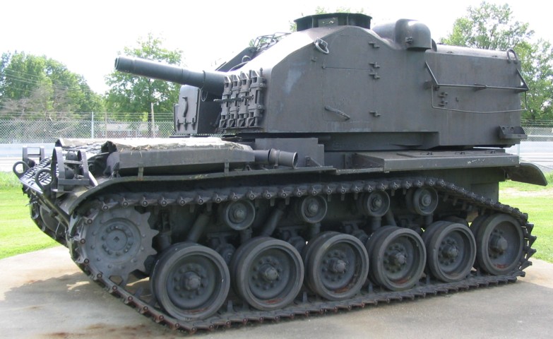
105mm Self-propelled Howitzer M52.
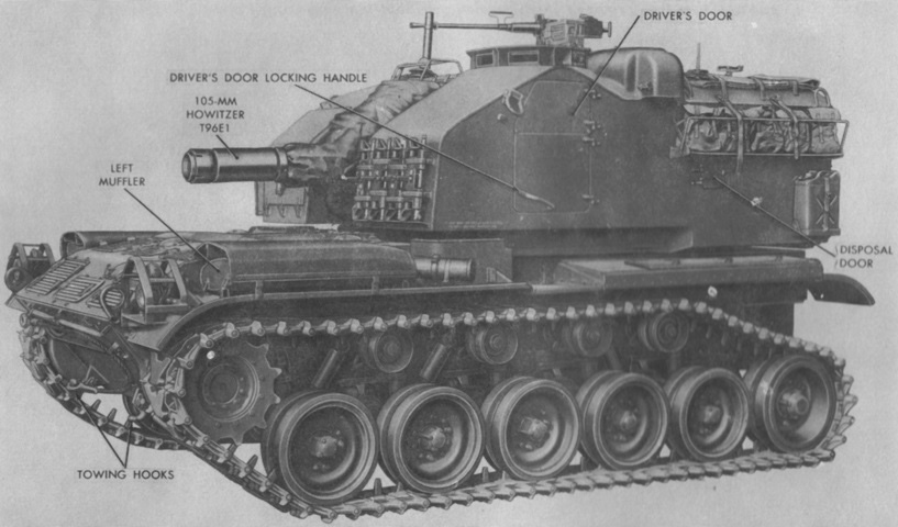
The M52 was based on the M41 tank, but with the drivetrain reversed. The sprocket was mounted to the front, and a large trailing idler was added. The driver's position is visible on the turret left front corner, and a ventilating blower duct is directly behind it. Note the two-piece driver's door; the upper section could be opened without opening the lower section. Spare T91E3 track blocks are stored on the front of the turret. (Picture from TM 9-7204.)
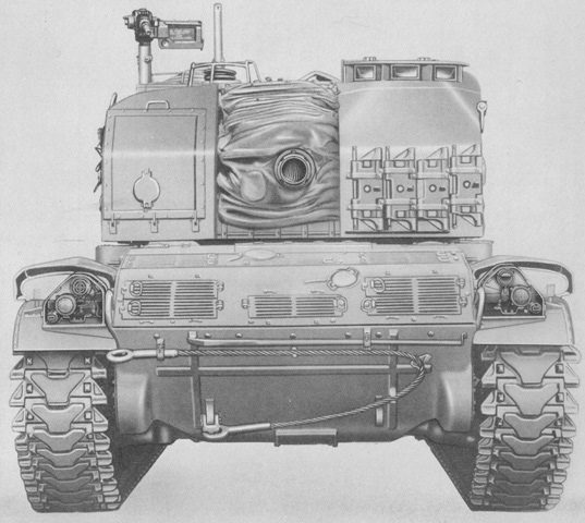
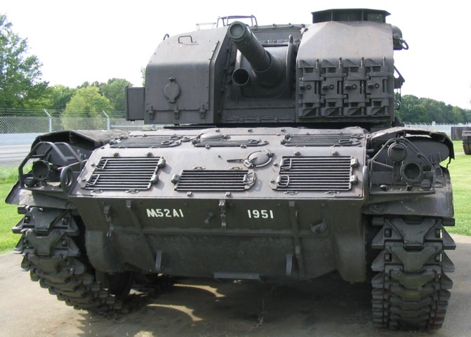
This head-on view highlights the asymmetric nature of the turret and howitzer mount. (Picture from ORD 9 SNL G-258.)
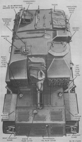
Further tool stowage and crew doors are visible on the turret roof. The driver was at the front left of the turret with the gunner to the front right. The gunner's periscope and panoramic telescope can be seen emerging from the front right corner of the turret roof. The commander was at the right rear of the turret. (Picture from TM 9-7204.)
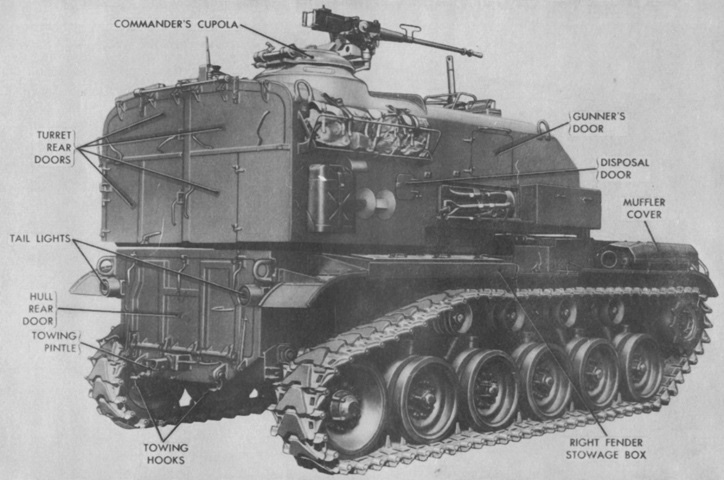
Pioneer tool stowage on the turret side can be seen, as well as the arrangement of the rear doors. Ammunition racks were accessible through the rear doors. (Picture from TM 9-7204.)
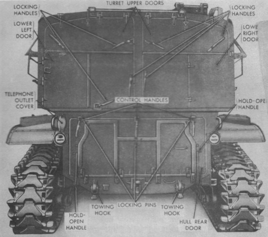
A late-production vehicle is seen here from the rear. On early production vehicles, the lower left turret door was opened by opening the upper left door, then by releasing two locking handles on the outside of the lower left door and swinging the door down. On late vehicles, the two locking handles on the lower left door were released, then the door was opened and folded in the center. A spring-loaded door catch was used to secure the door in the open position. Early vehicles also had a ladder secured to the lower left door. (Picture from TM 9-7204.)
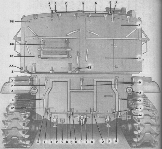
The earlier type of turret door arrangement is illustrated by this machine. Vehicles serial numbers 3-160 used the early door, while the later doors were used on vehicles serial numbers 161 and above. Note that the legend apparently contains an error: the label for "Y" may have been skipped, so starting there all the labels may need to be pushed back by one letter. A. Link, assy. B. Bracket, assy. C. Tube. D. Bracket. E. Bracket, assy. F. Door, assy. G. Door, assy. H. Handle. J. Light, assy. K. Shaft. L. Hinge, assy. M. Support. N. Hinge. P. Hook. Q. Hinge. R. Hinge. S. Bolt. T. Pintle, assy. U. Bar. V. Cover, assy. W. Door, assy. X. Light, assy. Y. Bar. Z. Anchor. AA. Door, assy. BB. Ladder, assy. CC. Door, assy. DD. Anchor. (Picture from ORD 9 SNL G-258.)

The ladder mounted on the turret lower left rear door on vehicles serial numbers 3-160 is diagrammed here. (Picture from ORD 9 SNL G-258.)
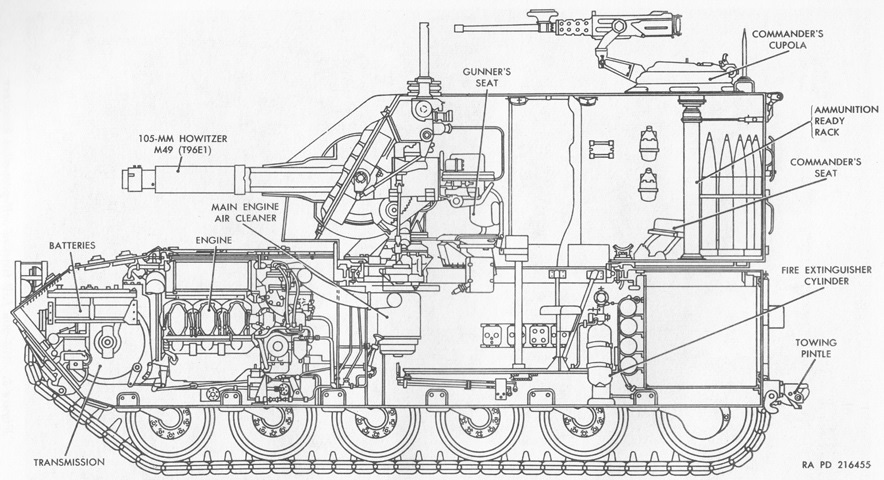
The internal arrangement is revealed in this cross-section. (Picture from TM 9-7204.)
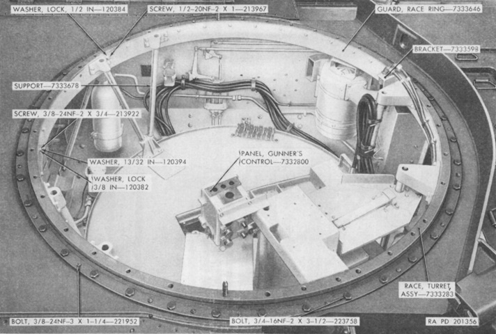
The turret has been removed, allowing a view of the turret race and interior including the turret basket. The hull front is to the right of the image, and an engine air cleaner is visible below the pointer for the race ring guard. (Picture from TM 9-7205-1.)
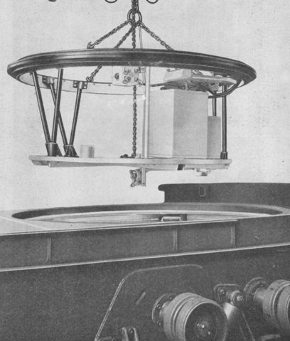
The turret basket can be seen in the process of being removed from the hull. (Picture from TM 9-7205-1.)
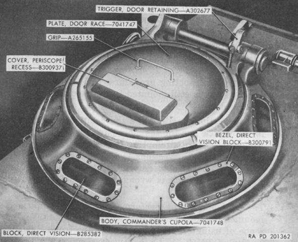
The commander's cupola is detailed in this picture. The cupola body was bolted to the turret roof, and this was equipped with six vision blocks. The door race plate could be rotated through 360°, and a periscope M15A1 could be mounted in it. An azimuth scale and pointer were on the interior of the cupola for use with the periscope. A rotating ring, to which the machine gun mount was attached, revolved on the stationary ring. (Picture from TM 9-7205-1.)
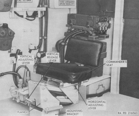
The commander's position is shown here. Like the gunner's and driver's seats, three vertical positions were available. (Picture from TM 9-7204.)
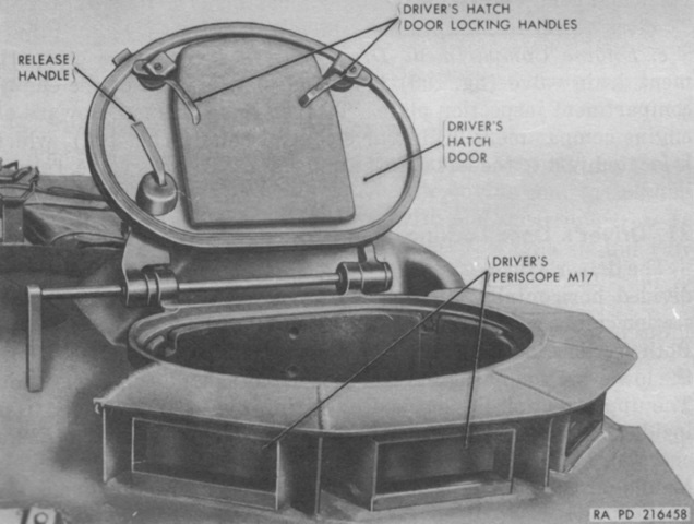
Details of the driver's periscopes and counterbalanced hatch door are shown in this picture. (Picture from TM 9-7204.)
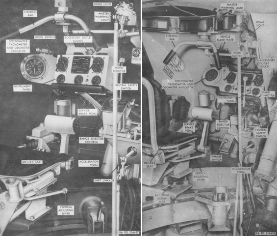
The driver's stations in an early (left) and late (right) vehicle are detailed in this image. The early instrument panel was used in vehicles with serial numbers 3-344, and the late instrument panel was used on vehicles serial numbers 345 and up. (Picture from TM 9-7204.)
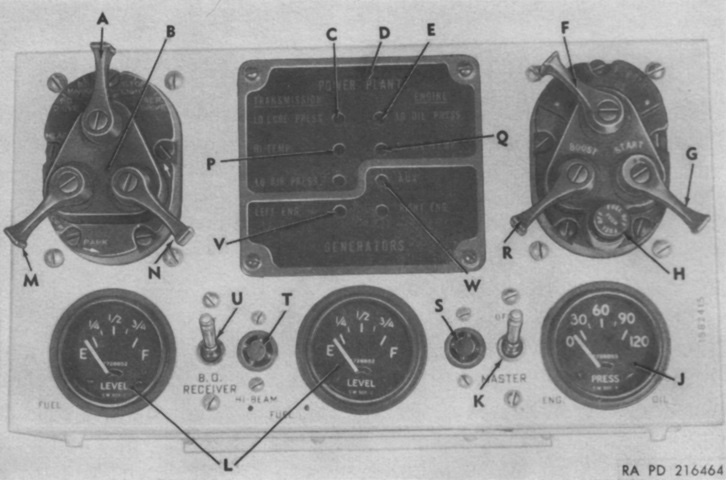
The driver's instrument panel is labeled here. A. Driving light switch. B. Driving light controls. C. Transmission low oil pressure warning light. D. Warning light panel. E. Engine low oil pressure warning light. F. Engine magneto switch. G. Engine starter switch. H. Fuel cutoff switch. J. Engine oil pressure gage. K. Master relay switch. L. Fuel gages. M. Auxiliary switch. N. Safety switch. P. Transmission high oil temperature warning light. Q. Engine high oil temperature warning light. R. Engine magneto booster switch. S. Master relay switch indicator light (late vehicles only). T. High beam indicator light (late vehicles only). U. Blackout receiver switch (late vehicles only). V. Generator warning light. W. Auxiliary generator warning light. (Picture from TM 9-7204.)
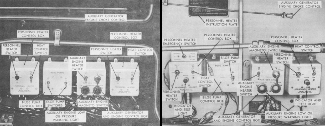
Although the auxiliary generator and engine were eliminated during production, provision for mounting one and its controls remained. The control box for the auxiliary generator and engine were mounted along the right side turret wall, along with the choke control for the auxiliary engine and control boxes for the bilge pump (only installed when the deep-water fording kit was installed) and personnel heaters. The controls for an early (left) and late (right) vehicle are both illustrated. The early personnel heater controls were used on vehicles with serial numbers 3-344, while the early bilge pump controls were used on vehicles 3 through 231. The late controls appeared on vehicles with higher serial numbers. The forward heater control box was for the left-hand heater, with the rear box controlling the right heater. (Picture from TM 9-7204.)
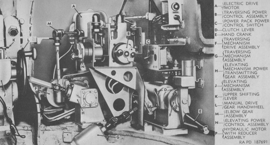
As originally designed, the prototype T98E1 featured an hydraulic traversing and elevating system, but trouble with the prototypes led to modifications including the deletion of the hydraulic system. (Picture from TM 9-7205-2.)
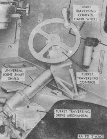
The manual turret traversing handwheel was situated to the gunner's front right; his seat is at the lower right corner of the image. The handwheel drove bevel gears linked to a universal joint shaft and gear train in the turret traversing drive mechanism; the pinion of this mechanism meshed with the turret race ring gear. (Picture from TM 9-7204.)
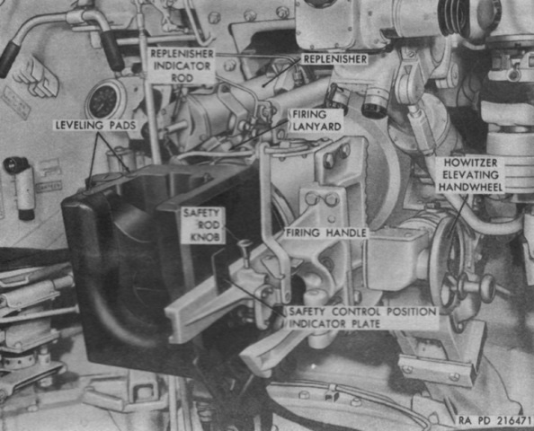
The elevation handwheel was to the gunner's left. This handwheel operated a worm and pinion gear in the speed reduction unit that drove a pinion that meshed with the elevating segment on the howitzer mount. (Picture from TM 9-7204.)
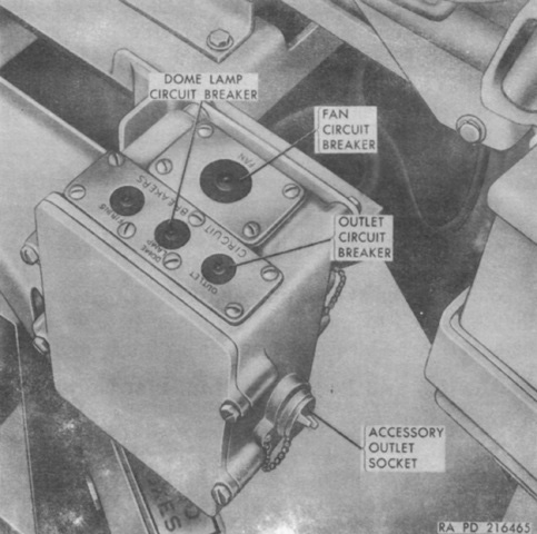
The gunner's control box was attached to the left side of the his seat support. On the side of the box opposite the accessory outlet socket was the on/off switch for the ventilating fan. The unlabeled forward circuit breaker on the box was for the firing circuit; this breaker was inoperative. (Picture from TM 9-7204.)
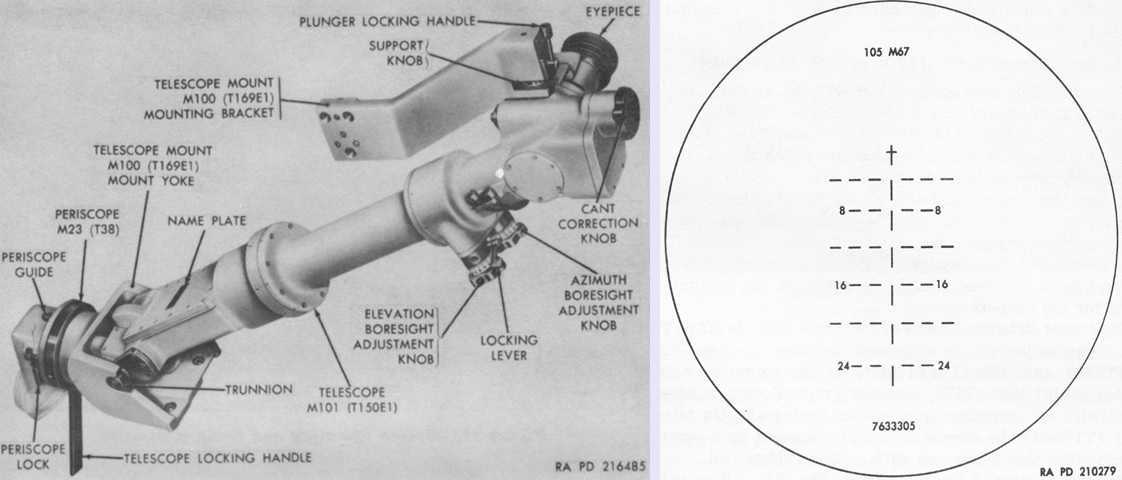
The unity periscope M23 and 4x telescope M101 were used to lay the howitzer in direct fire. Both the M23 and M101 had 10° fields of vision; the line of sight through the M23 was depressed 2°15' ± 2' in elevation with respect to a line of sight through the periscope's upper window. The reticle for the M101 is sketched on the right, and was calibrated for the 105mm HEAT shell M67. The cross represented zero range or deflection and was used for boresighting. Each line and space of the vertical center line represented 200 yards (180m) range, and each segment and space of the horizontal lines represented a 5-mil deflection. (Picture from TM 9-7204.)
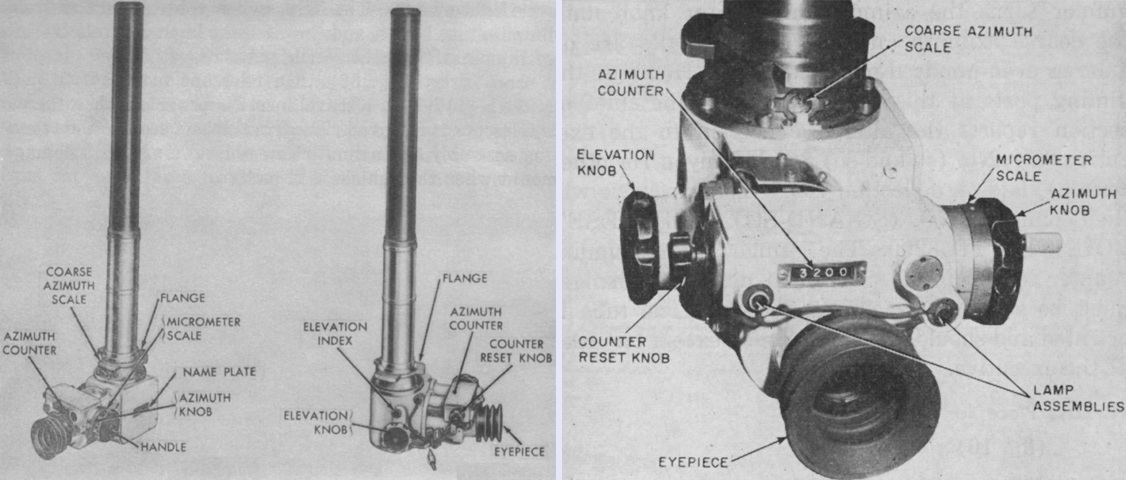
The panoramic telescope M100 was a 4x device with a 10° field of view, and was used to lay the howitzer for indirect fire. (Pictures from TM 9-7204 and FM 6-77 105-mm Howitzer M52 Self-propelled.)
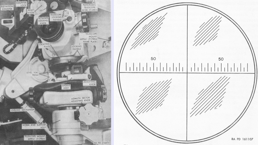
The panoramic telescope M100 was mounted in the telescope mount M99 or M99A1, the latter of which is the version featured in this picture. The mounts incorporated a cant correction mechanism that, when cross- and longitudinally-leveled, indicated the error in azimuth when sighting through the panoramic telescope at a fixed aiming point that was induced by elevating the howitzer with the trunnion canted. The M99 had a curved support assembly with an accordion-type rubber dust boot; the M99A1 had a worm and nut mechanism instead of the curved support, and the rubber dust seal was a plain type. The reticle pattern for the M100 is drawn on the right. The intersection of the vertical and horizontal cross lines served to sight the telescope on the aiming point, and a deflection scale was graduated in 5-mil intervals up to 90 mils to each side of the center vertical line. (Picture from TM 9-7204.)
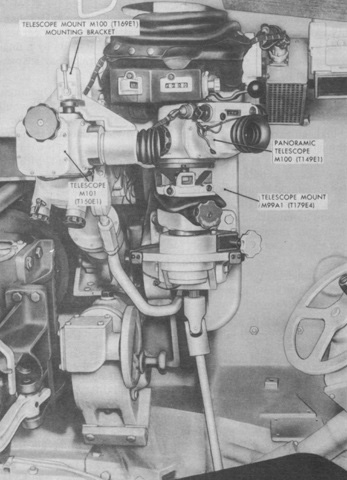
This overview of the gunner's position shows both the spatial relationship between the panoramic telescope M100 and the telescope M101 as well as the traversing and elevation handwheels. (Picture from TM 9-7204.)
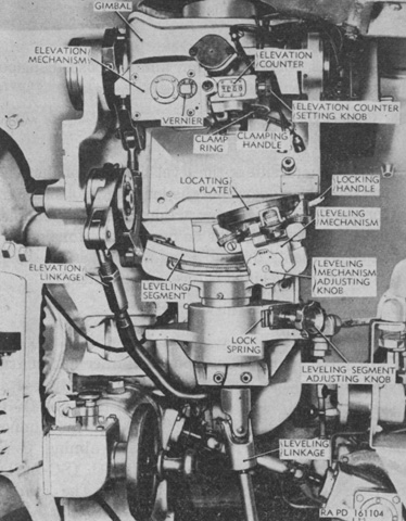
More details of the gunner's telescope mount are shown in this image. (Picture from FM 6-77 105-mm Howitzer M52 Self-propelled.)
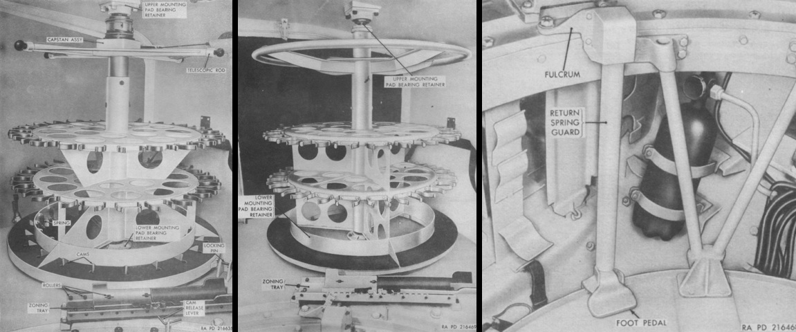
A rotary ready rack occupied the rear of the turret. When a shell was removed, the cam on which it rested was released, and the rack would automatically spin until arrested by the next cam depressed by a shell. Racks used on vehicles with serial numbers 2 through 200, shown on the left, had a cam release lever that could be turned up and pushed in to let the rack spin freely. Instead of the cam release lever, racks used in vehicles with serial numbers of 201 and higher (center image) could be spun by stepping on a foot pedal, shown on the right. When a shell was removed from the ready rack, it was placed on the zoning tray in front of the rack, where the shell was split and charged with powder. The tray was then moved left on integral rollers, so that the fuse setter mounted by the tray could be used. (Picture from TM 9-7204.)
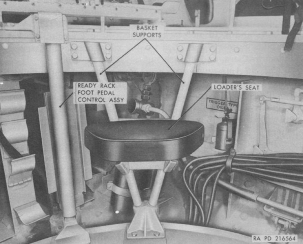
While the commander, gunner, and driver sat in bucket-type seats with removable backrests, the loaders made due with seats that could be installed when desired onto supports connected to the turret basket. (Picture from TM 9-7204.)
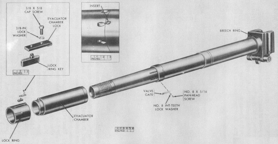
A partially exploded view of the 105mm howitzer M49 is given here. It used a vertical sliding breechblock, and weighed 930lb (420kg) complete. Maximum range was 12,150 yards (11,110m). (Picture from TM 9-7204.)
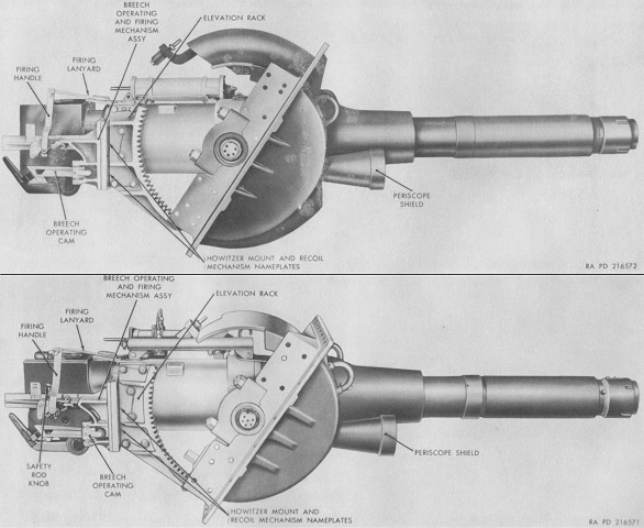
Early (top) and late (bottom) versions of the howitzer mount M85 are shown here. (Picture from TM 9-7204.)
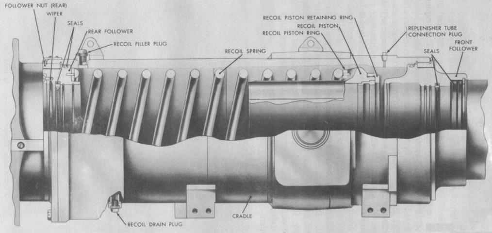
A cross-section of the recoil system is diagrammed in this image. It was a concentric hydrospring constant recoil distance type with a normal recoil length of 11.75" (29.85cm) and a maximum of 13" (33cm). When the ordnance was fired, the recoil piston attached to the howitzer tube was driven rearward with the tube itself. As the piston moved, recoil oil flowed around it, and the farther rearward the piston traveled the smaller the clearance between the piston and the bore of the cradle became, thereby increasing the resistance of the flow of the oil. The recoil spring was also compressed during firing, assisting with the arrest of rearward motion. During counterrecoil, the compressed spring forced the ordnance back into battery, and a buffer regulator cushioned the impact so the howitzer returned to battery with a minimum of shock. Including the replenisher, the recoil system's capacity was 3.5gal (13L) of oil. (Picture from TM 9-7204.)
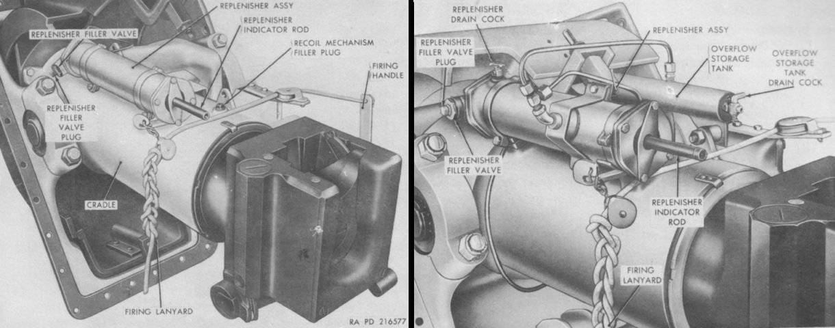
The replenisher assembly constantly kept the recoil oil under pressure. It allowed the oil to expand as its temperature increased by forcing the internal sprung piston to the rear, and this same sprung piston would force additional oil into the recoil system due to contraction due to decreased temperature, leaks, etc. The indicator rod, attached to the piston, was marked with graduations alerting the crew when to fill or bleed the replenisher. Late-production vehicles (right) had an overflow storage tank connected to the replenisher. (Picture from TM 9-7204.)
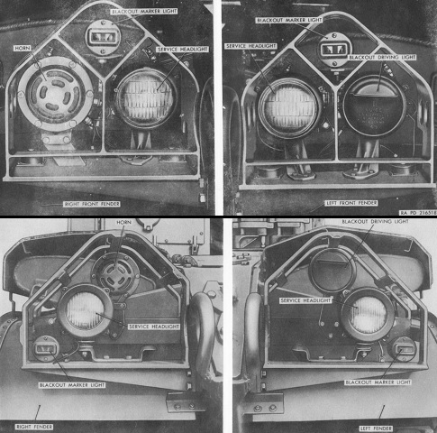
The headlight clusters of an early (top) and late (bottom) vehicle can be compared; the later headlights were introduced with vehicle serial number 465. Note the more open brush guard design on the late machine. (Picture from TM 9-7204.)
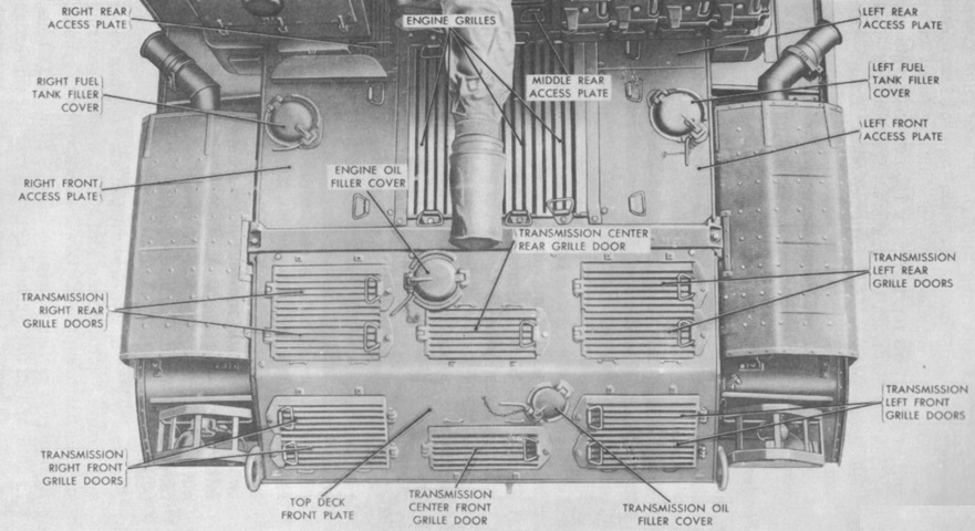
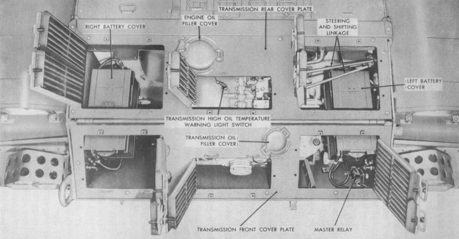
The various engine and transmission doors and grilles are labeled on this late vehicle. (Picture from TM 9-7204.)
This early machine has the transmission access doors opened. Note the headlight brush guard design in contrast to the late vehicle. (Picture from TM 9-7204.)
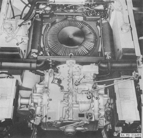
The engine compartment is shown here with the covering plates removed. The letters refer to disconnect points for the engine and transmission. (Picture from TM 9-7204.)
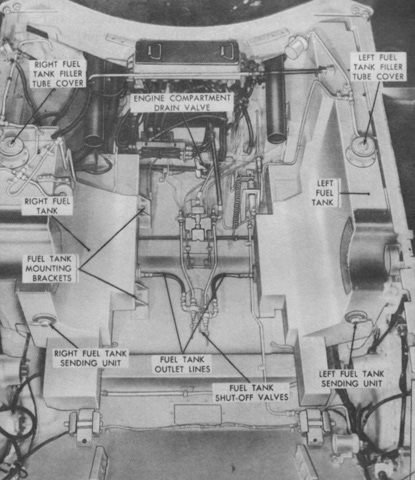
The engine compartment is shown here with the engine and transmission dismounted. The two fuel tanks were filled individually: the left tank held 93gal (350L) and the right tank 81gal (310L). (Picture from TM 9-7204.)
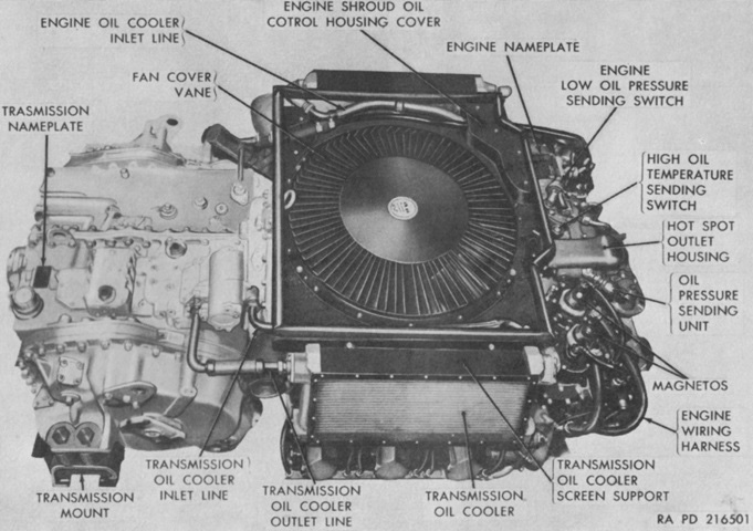
The top of the engine and transmission, shared with the 76mm gun tank M41 are labeled in this image. Its compression ratio was 5.5:1. (Picture from TM 9-7204.)
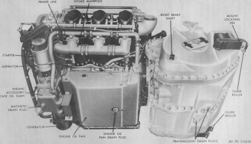
The bottom of the engine and transmission can be seen. Running at 2,800rpm, the engine could be expected to consume 1gal (3.8L) of oil every hour. (Picture from TM 9-7204.)
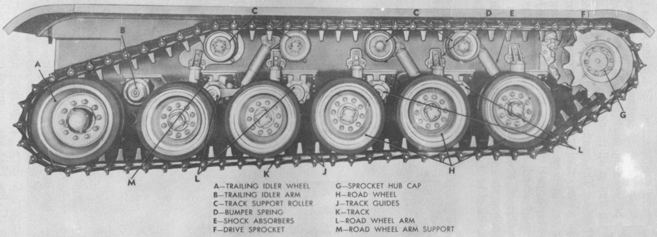
Parts of the suspension are labeled in this image. Although a 12-tooth drive sprocket is shown mounted, 13-tooth sprockets began to be supplied as replacement parts sometime between January and September 1957. (Picture from TM 9-7204.)
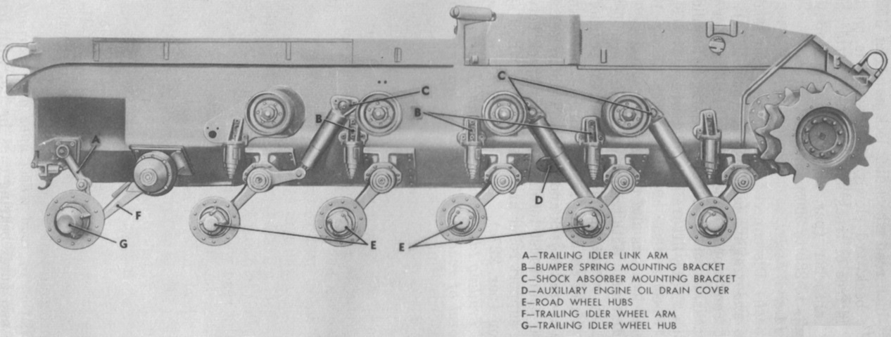
Another view of the suspension and hull side is provided with the running gear removed. The design originally had a shock absorber connected to the trailing idler wheel, but this was omitted during production. The vestigial mounting holes behind the rear road wheel's bumper spring seem surprised at the shock absorber's absence. (Picture from TM 9-7204.)
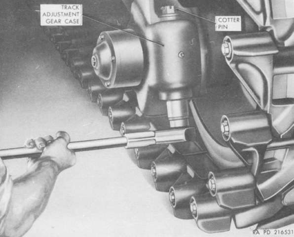
The track adjustment gear case contained a worm gear used to adjust the idler wheel to tighten or loosen track tension. (Picture from TM 9-7204.)
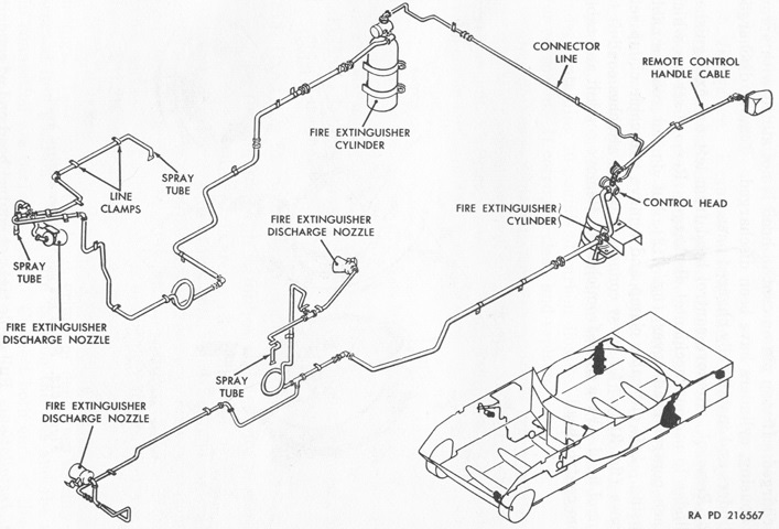
The fixed fire extinguisher system consisted of a 10lb (4.5kg) CO2 cylinder mounted on each side of the fighting compartment forward of the rear ammunition rack. The cylinders were routed to three discharge nozzles and three spray tubes to smother fires in the engine compartment, as shown in the diagram. Both cylinders were discharged simultaneously by activating the control head on the left cylinder or by pulling the remote control handle on the exterior of the left rear hull. In addition, a portable 5lb (2.3kg) extinguisher was mounted in a bracket behind the driver's seat. (Picture from TM 9-7204.)
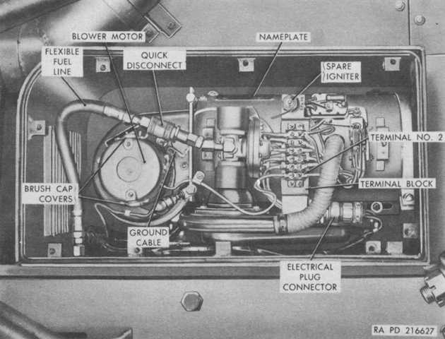
A Stewart Warner Model 978M-R24 gasoline-fueled personnel heater was installed on each side of the hull in a special compartment behind each main engine muffler. Each heater weighed 23lb (10kg) and had an output capacity of 20,000BTU/hour. A common electric fuel pump fed both heaters from the main fuel tanks, with each one consuming 1gal (3.8L) of gasoline every 4 hours on the high setting and every 8 hours on the low setting. (Picture from TM 9-7204.)
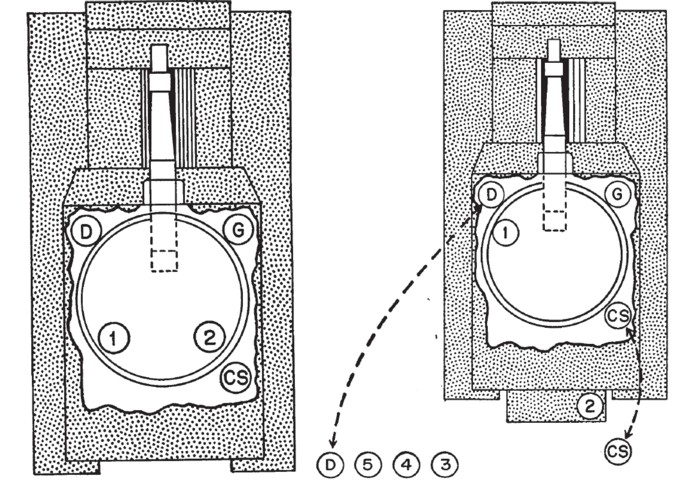
The crew positions are shown here mounted for travel (on the left) and ready for action (on the right). CS is the chief of section, G is the gunner, D is the driver, 1 is the assistant gunner, and 2-5 are cannoneers. (Picture from FM 6-77 105-mm Howitzer M52 Self-propelled.)
This M52A1 is differentiated by its fuel-injected vice carbureted engine, and is externally similar to the earlier version.
The outboard guard on the right side of the turret roof was for the gunner's periscope M13, and the larger inboard guard protected his panoramic telescope M100.
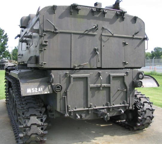
This rear view shows the turret and hull doors. A towing pintle is located at the center of the bottom hull. The commander's cupola with its .50cal machine gun mount is visible on the right side of the turret roof, and an antenna mast base is near the center of the turret roof rear.
