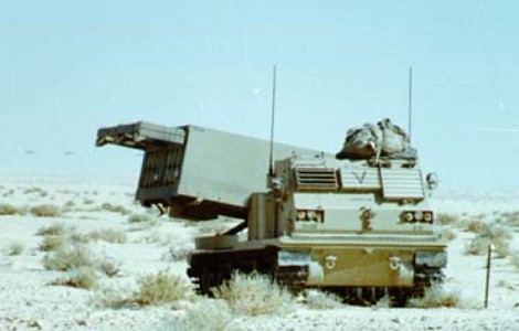
Multiple Launch Rocket System M270 in Saudi Arabia.
The M993 carrier for the MLRS is based on components of the M2 and M3 Bradley, and the two six-rocket pods take up the entire rear of the vehicle. The cab is fitted with armored windows which also feature armored shutters to protect the cab during launch. Here the launcher is in firing position, and the girder structure above the rocket pods is a crane which is extended to facilitate loading the rocket pods into the launcher. (Picture taken 17 Dec 1990 by Sgt. Randall M. Yackiel; available from the US Army Center of Military History.)
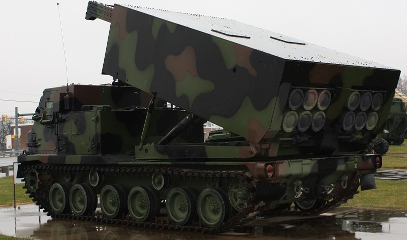
This rear view displays the suspension changes versus the Bradley fighting vehicles on which the carrier is based. The road wheels are spaced out in three pairs, and there are two dual return rollers in the center and two single return rollers at each end of the vehicle. The engine is behind and under the cab, and the engine access door can be seen on the side of the engine compartment above the first pair of road wheels. The engine exhaust grille is on the opposite side of the engine compartment. The driver's personnel door can be seen in the side of the cab, and the storage compartment for the boom controller is outboard of the left rocket pod on the rear of the launcher loader module. The rear storage compartment on the opposite side housed the short no-voltage tester. (Photo by Richard S. Eshleman.)
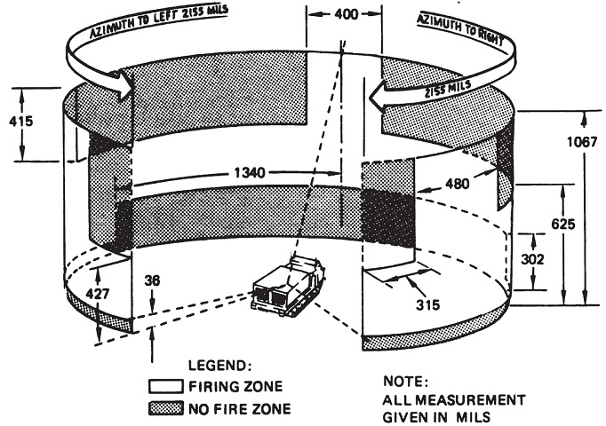
Firing angle limits were imposed by factors including rocket blast and the vehicle's cab and engine housing. The fire control system was able to compute safe firing angles (and prevent firing into a no fire zone), and these are illustrated in this diagram. (Picture from TM 9-1425-646-10 Operator's Manual Launcher, Rocket, Armored Vehicle Mounted: M270 (1055-01-092-0596) Multiple Launch Rocket System.)
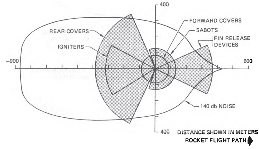
Danger areas around the launcher are shown here. Toxic gases are also emitted, and personnel were instructed to wear NBC masks if they were positioned downwind from a firing launcher. (Picture from TM 9-1425-646-10 Operator's Manual Launcher, Rocket, Armored Vehicle Mounted: M270 (1055-01-092-0596) Multiple Launch Rocket System.)
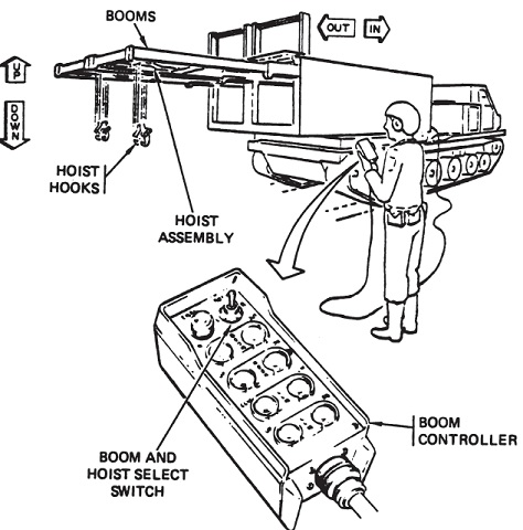
The operation of the booms and hoists is shown here. From top to bottom, the buttons on the left column of the controller are the ENBL indicator light, the BOOM IN switch (retracts the boom[s]), the HOOK UP switch (raises the boom hook[s]), the LLM CCW switch (turns the launcher loader module counterclockwise), and the LLM UP switch (elevates the front of the launcher loader module). The right column consists of the L BOTH R switch (select a single boom or hoist or both at once), the BOOM OUT switch (extends the boom[s]), the HOOK DN switch (lowers the boom hook[s]), the LLM CW switch (turns the launcer loader module clockwise), and the LLM DN switch (lowers the front of the launcher loader module). (Picture from TM 9-1425-646-10 Operator's Manual Launcher, Rocket, Armored Vehicle Mounted: M270 (1055-01-092-0596) Multiple Launch Rocket System.)
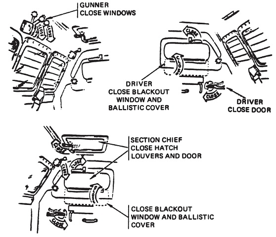
The crew was to lock down the cab doors, hatches, and louvres as well as engage the cab ventilation system to prevent rocket exhaust from entering. The vehicle would realize if this was not done and would sound a warning to alert the crew. (Picture from TM 9-1425-646-10 Operator's Manual Launcher, Rocket, Armored Vehicle Mounted: M270 (1055-01-092-0596) Multiple Launch Rocket System.)
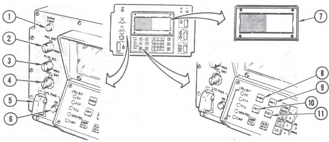
The fire control panel controls and indicators are detailed in these images. 1. BOOM CONT indicator light comes on after the boom controller operation is selected and is ready for use. 2. PNL BRT knob sets brightness of indicator lights on the fire control panel. 3. ALM VOL knob sets volume of the incoming message and cab alarm signal. 4. DSPL BRT switch sets brightness of lighted messages on the fire control panel display and the LRU BIT indicator lights. 5. SYS PWR switch applies electrical power to the fire control system and other launcher loader module units. 6. SYS PWR indicator light illuminates when the electrical power applied to the fire control system is of the appropriate voltage. 7. FCP display shows fire control system prompts; the shaded area shows where the data and prompts will appear. 8. INDEX key brings up a list of operating routines on the fire control panel display. 9. XMIT key sends a radio message to the battery and/or platoon leader. 10. INIT key shows launcher lay instructions on the fire control panel and enables the LCHR LAY key. 11. EXEC key causes the fire control system to start using the data or command inputted by the operator. (Picture from TM 9-1425-646-10 Operator's Manual Launcher, Rocket, Armored Vehicle Mounted: M270 (1055-01-092-0596) Multiple Launch Rocket System.)
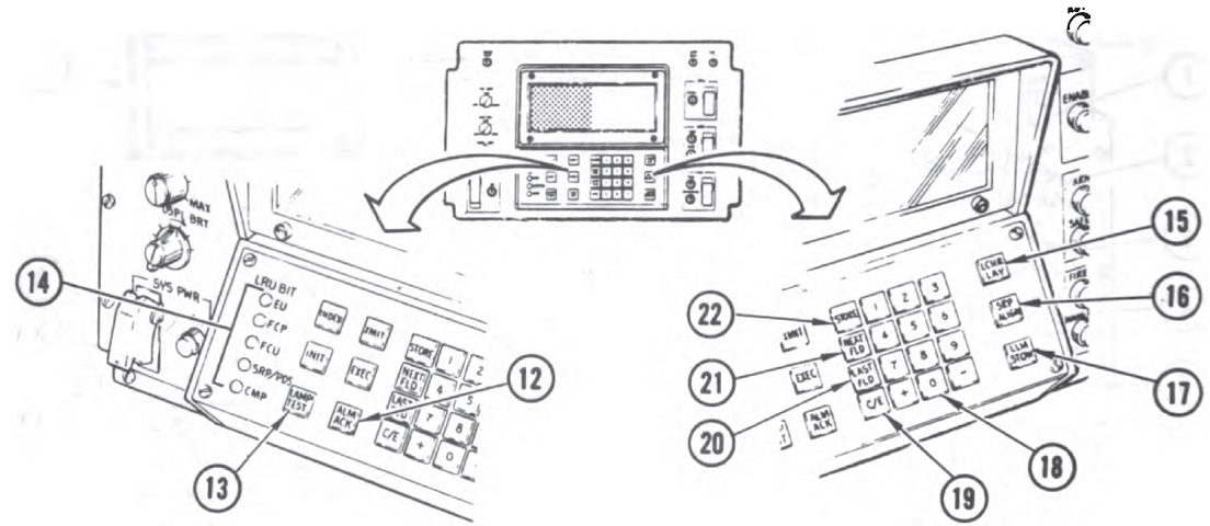
12. ALM ACK key silences an audible alarm and makes the fire control system process an incoming message. 13. LAMP TEST key illuminates all fire control panel lights and sounds the audible alarm for 5 seconds. 14. LRU BIT indicator lights illuminate when a major unit of the fire control system has a fault. 15. LCHR LAY key initiates the automatic fire control mission operation. 16. SRP ALIGN key causes the stabilization reference package to go through a realign sequence. 17. LLM STOW key initiates the launcher loader module's stow operation. 18. Numeric keyboard. 19. C/E key clears nonstored entries from the fire control panel display and erases fire control system fault prompts. 20. LAST FLD key returns the fire control panel display to the previous field. 21. NEXT FLD key advances the fire control panel display to the next field. 22. STORE key stores data on the fire control panel display into the fire control system. (Picture from TM 9-1425-646-10 Operator's Manual Launcher, Rocket, Armored Vehicle Mounted: M270 (1055-01-092-0596) Multiple Launch Rocket System.)
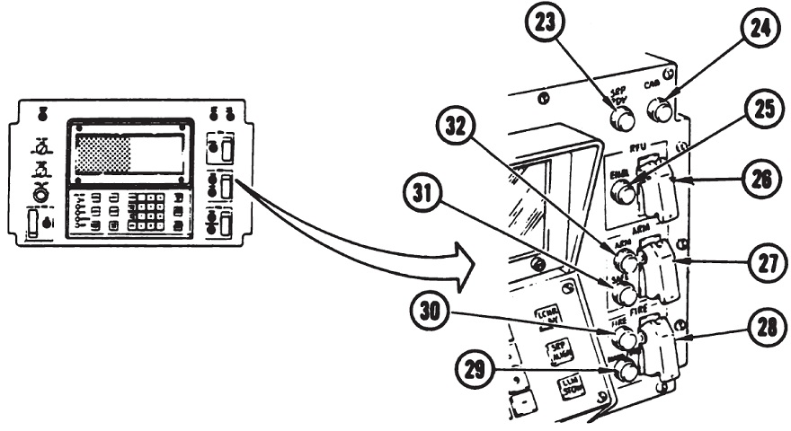
23. SRP RDY indicator light illuminates when the stabilization reference package is aligned and ready. 24. CAB indicator light illuminates when a cab hatch or door is not shut, or when the ventilation system is not properly set during a fire mission. 25. RFU ENBL indicator light is not used. 26. RFU switch is not used. 27. ARM switch arms or safes the rockets selected for firing. 28. FIRE switch causes the fire control system to start firing the selected and armed rockets. Firing will continue automatically after the switch is released. 29. HANGFIRE indicator light flashes when firing did not occur after power was applied to a rocket igniter squib. 30. FIRE indicator light illuminates during the firing sequence. 31. SAFE indicator light illuminates when the system is not armed. 32. ARM indicator light illuminates when the system is armed. (Picture from TM 9-1425-646-10 Operator's Manual Launcher, Rocket, Armored Vehicle Mounted: M270 (1055-01-092-0596) Multiple Launch Rocket System.)

33. FCS elapsed time meter indicates the total time the FCP SYS PWR switch has been on. 34. Pressure relief valve equalizes air pressure in the fire control panel with outside air pressure. 35. Audible alarm sounds when a message from the battery or platoon leader has been received, beeps when the fire control panel keyboard is pressed, or sounds when a cab door or hatch is open during a fire mission or if the ventilation system is not properly set. (Picture from TM 9-1425-646-10 Operator's Manual Launcher, Rocket, Armored Vehicle Mounted: M270 (1055-01-092-0596) Multiple Launch Rocket System.)
