Mine Excavator T5E3.
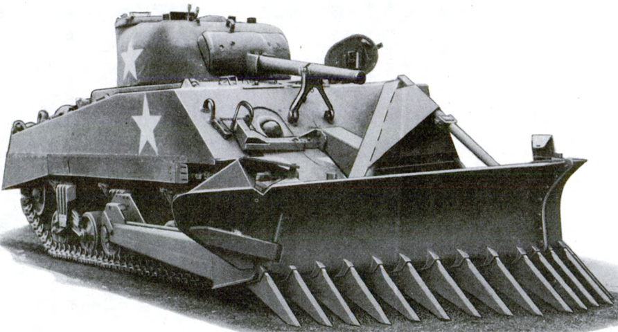
The mine excavator T5E3 was a V-shaped rake-type blade that was intended to remove land mines ahead of a moving tank. Twenty-two 117lb (53.1kg) teeth were secured to the bottom of the blade with 4¾" (12.1cm) between adjacent teeth and 6" (15cm) between the centers of adjacent teeth. The teeth penetrated 14" (36cm) below the ground, and when raised the front tooth was 60½" (154cm) high and the rear tooth 41½" (105cm) high. The maximum drop of the front and rear teeth was 28¾" (73.03cm) and 23½" (59.7cm), respectively. Folding wings on the sides of the blade prevented the mines from falling back into the tank's path. The excavator weighed 9,960lb (4,518kg), was 168" (427cm) wide overall with the wings extended, and was 130" (330cm) wide with the wings folded. The moldboard was 32" (81cm) high. The medium tank M4A3 was the preferred mount due to the copious torque produced by its GAA engine. The tank was 313" (795cm) long overall with the excavator mounted, and its angle of approach was 27°30'. (Picture from TM 9-733 Mine Excavator T5E3.)
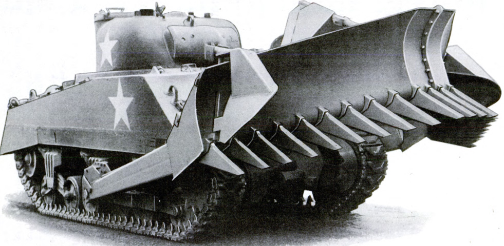
The T5E3 was approved as a limited procurement item in June 1944, and the La Plante-Choate Company manufactured 100 kits between March and May 1945, in time for use in the Pacific Theater during World War II. The excavator is seen here raised via the hydraulic jack that controlled the blade. The blade was built up from right and left-hand assemblies that bolted together to form a blunt-pointed "V." The noses of the two assembles were flanged on the top, inside, and outside, and twenty-four ¾" (1.9cm) bolts and lock washers secured the two noses to each other. The rears of the blade assemblies were connected by a flanged, box-type crossbeam fastened by fourteen ⅝" (1.59cm) bolts and lock washers. The curved moldboard was composed of welded armor plates, and eleven teeth were installed at the bottom of each of the two blade assemblies. (Picture from TM 9-733 Mine Excavator T5E3.)
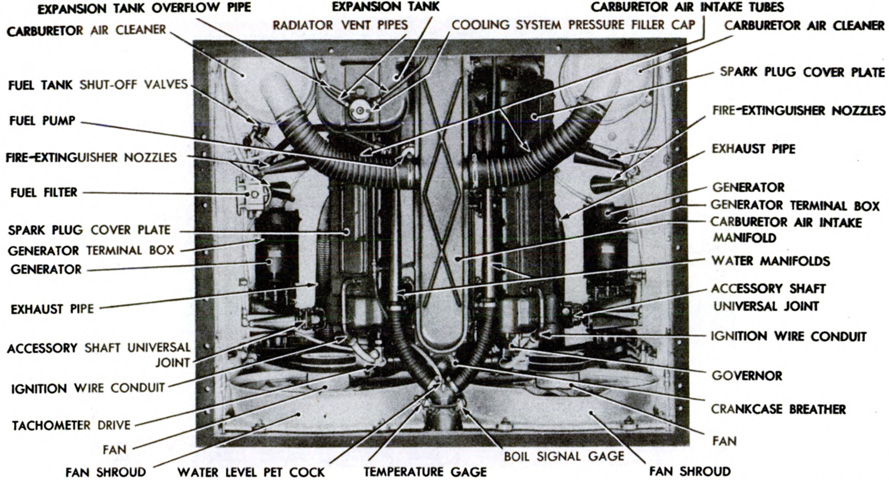
When the T5E3 was installed, the main generator on the floor behind the driver was replaced by a pair of generators mounted on the sides of the engine compartment. (Picture from TM 9-733 Mine Excavator T5E3.)
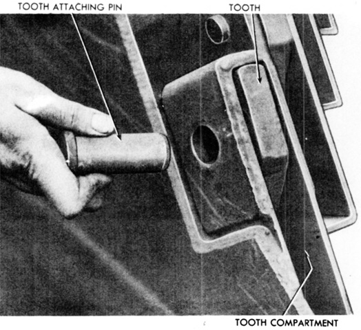
Each tooth was mounted in a slotted compartment and held in position by an attaching pin. Dirt was prevented from piling up around the teeth by a dirt shield that was attached by more pins to the upper inside edge of the main blade. (Picture from TM 9-733 Mine Excavator T5E3.)
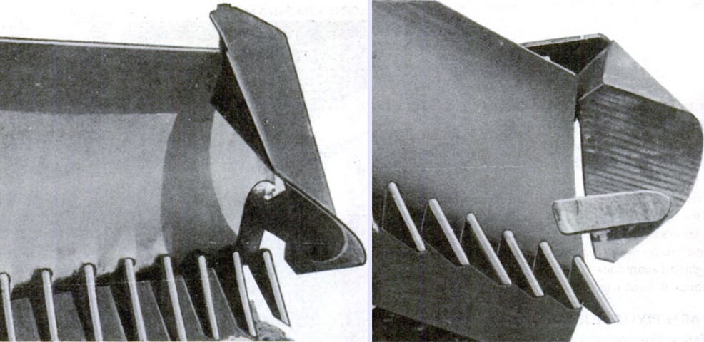
Each side of the blade had a wing mounted to the outer edge via a hinged pivot pin, which allowed the wings to swing out when excavating. A wing is seen here folded on the left and extended on the right. (Picture from TM 9-733 Mine Excavator T5E3.)
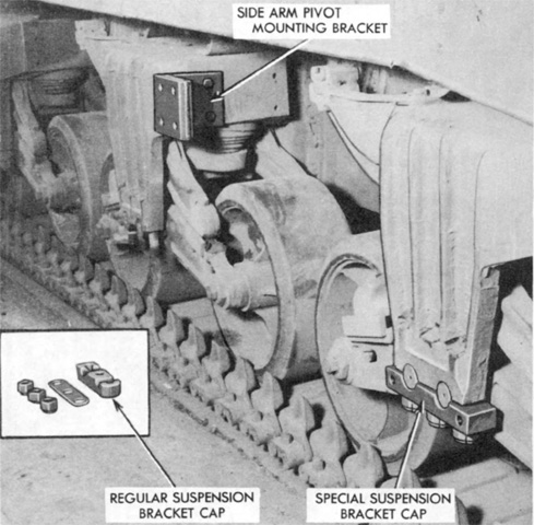
The blade's side arms were attached to a pivot mounting that was secured to the front two suspension bogies on each side of the tank. Hardware to install the pivot mount on the bogies is illustrated in this picture. (Picture from TM 9-733 Mine Excavator T5E3.)
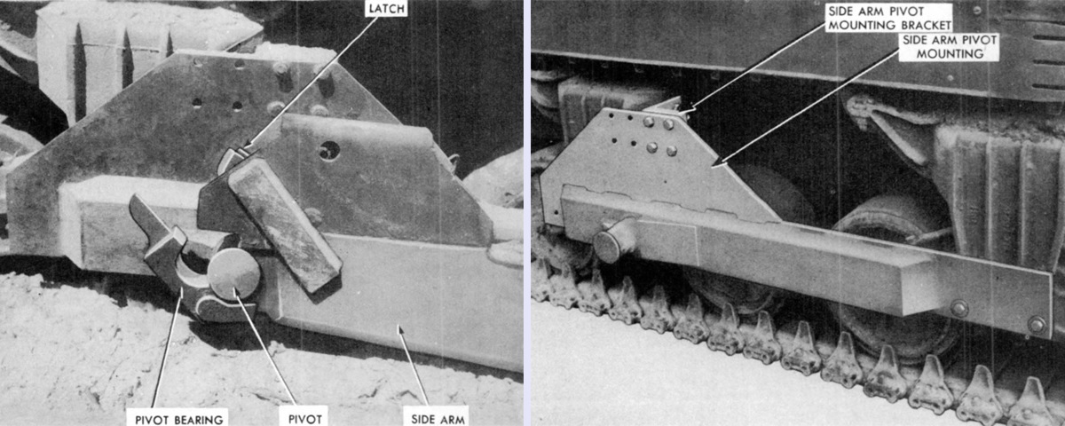
The pivot mounting is seen installed on the right. Two cap screws attached its lower front edge, four bolts secured the upper rear, and three studs located the mounting at the lower rear. A pivot pin welded to the mounting engaged the pivot bearing on the blade assembly's arm, and an arm is shown on the left in the process of being installed on the mounting. (Picture from TM 9-733 Mine Excavator T5E3.)
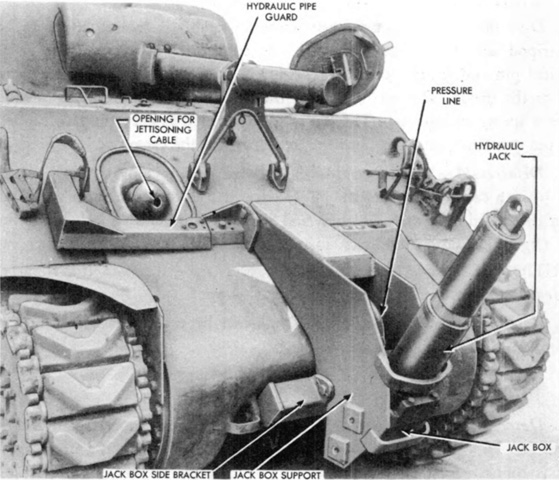
The blade was actuated by a three-section, telescopic hydraulic jack mounted on the hull front by a support bracket. The jack's lower section was mounted in a trunnion block, and the hydraulic line entered the jack through this section. The center section telescoped into the main section, and the upper section had a hole to connect the jack to the tripod assembly. A single-stage jack could be substituted, but mounting spacers were then required. Hydraulic lines were routed to the jack via the right-side headlight opening, and were protected by welded armor plate guards. (Picture from TM 9-733 Mine Excavator T5E3.)
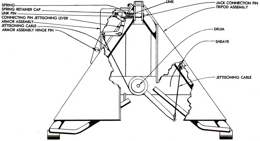
The tripod was of bar construction and protected by armor plate. The right and left side bars attached to the right and left arms of the blade assembly, and the forward bar extended downward to a link that was straddle-mounted to the inside flanges of the blade assemblies. (Picture from TM 9-733 Mine Excavator T5E3.)
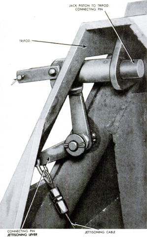
The assistant operator had access to a control lever that, when pulled, tensioned a cable running through the bow machine gun mount that simultaneously released the jack piston-to-tripod connecting pin and the latches on the side arm pivot bearings. This allowed the excavator to be jettisoned without requiring the crew to exit the tank. To accomplish this, the excavator was lowered and the tank driven forward to dig the blade into the ground. The jettisoning lever was pulled and the tank was slowly backed away until the jack piston cleared the tripod. The assistant operator was then to push the jettisoning lever forward again, which allowed the jettisoning cable to disengage the jettisoning lever and be pulled out from the tank through the bow machine gun opening. (Picture from TM 9-733 Mine Excavator T5E3.)
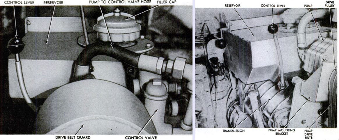
Internal components, including the hydraulic oil reservoir, control valve, and pump are shown mounted in the drivers' compartment on top of the transmission. (Picture from TM 9-733 Mine Excavator T5E3.)
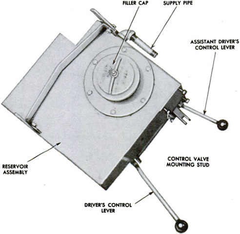
Hydraulic oil for the system was contained in a welded steel reservoir with internal baffles and a screen in the filler neck. It was mounted on brackets atop the front of the tank's transmission case, and an oil level gage was provided. The operator and assistant operator each had a control handle that actuated the control valve operating mechanism on the reservoir's lower rear edge. The levers had three positions: hold was in the neutral or vertical position, raise was to the rear, and lower was to the front. The levers would return to the neutral position when released. (Picture from TM 9-733 Mine Excavator T5E3.)
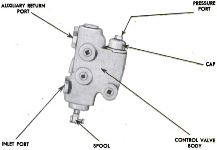
The hydraulic control valve was a cast-iron valve housing that contained a steel valve spool and a spring-loaded conical relief valve. The valve was mounted at the right rear of the reservoir on four ⅜" (.953cm) studs. (Picture from TM 9-733 Mine Excavator T5E3.)
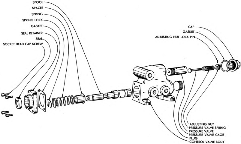
An exploded diagram of the control valve is drawn here. (Picture from TM 9-733 Mine Excavator T5E3.)
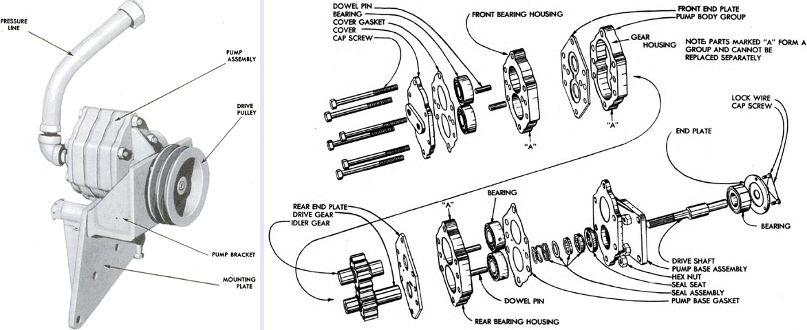
The hydraulic pump is seen assembled on the left and exploded on the right. It was a gear-type belt-driven pump mounted on a support bracket and adjusting plate at the rear of the tank's transmission. (Picture from TM 9-733 Mine Excavator T5E3.)
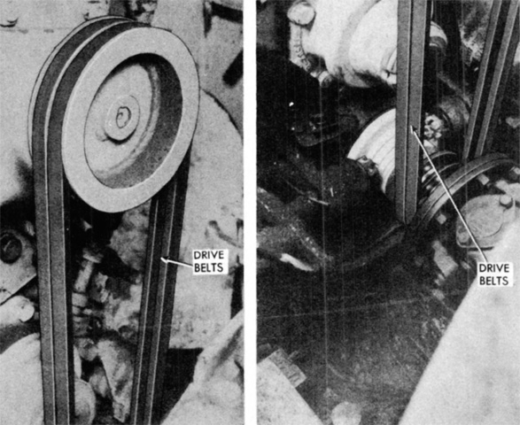
The pump was driven by endless V-type belts that were looped around pulleys on the pump and the transmission universal joint. Although seen above exposed, the belts were normally shielded by a welded steel guard attached to the rear of the transmission housing by four cap screws. (Picture from TM 9-733 Mine Excavator T5E3.)
