Light Tank M5 Stuart.
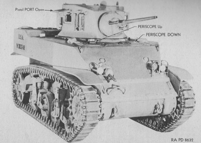
Compared to the light tank M3, the revised front hull armor profile is immediately apparent. The drivers were provided with hatches in the hull roof, and viewed through periscopes. (Picture from TM 9-732 Light Tanks M5 and M5A1.)
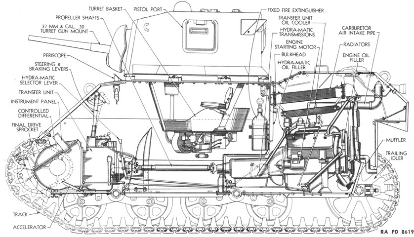
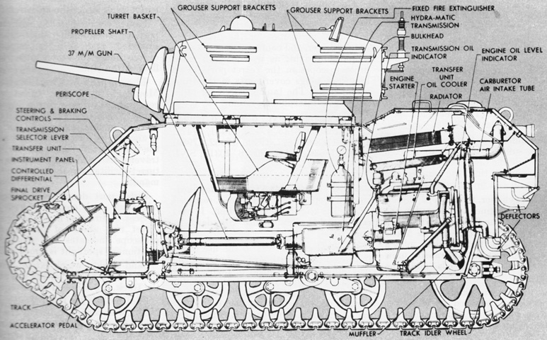
A cross-section is provided here. Note that, in contrast to the light tanks M3A1 and M3A3, the turret traverse mechanism is now underneath the turret basket floor thanks to the lower height taken up by the new power train. The reason for the raised rear hull can be seen, with the engine radiators placed above the engines. (Picture from TM 9-1727C Ordnance Maintenance--Hydra-matic Transmission and Propeller Shafts for Light Tanks M5, M5A1, and 75-mm Howitzer Motor Carriage M8.)
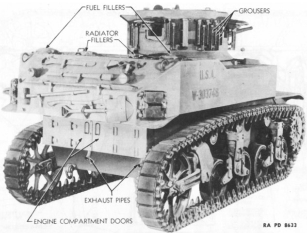
The rear of the vehicle is detailed in this image. (Picture from TM 9-1727C Ordnance Maintenance--Hydra-matic Transmission and Propeller Shafts for Light Tanks M5, M5A1, and 75-mm Howitzer Motor Carriage M8.)
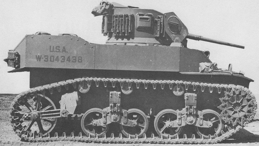
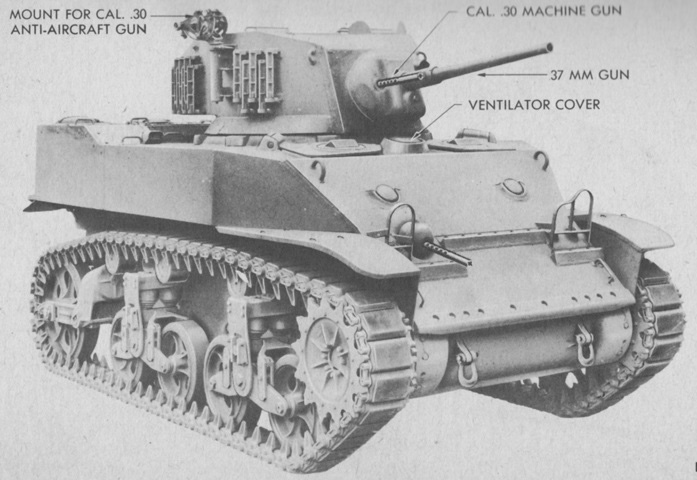
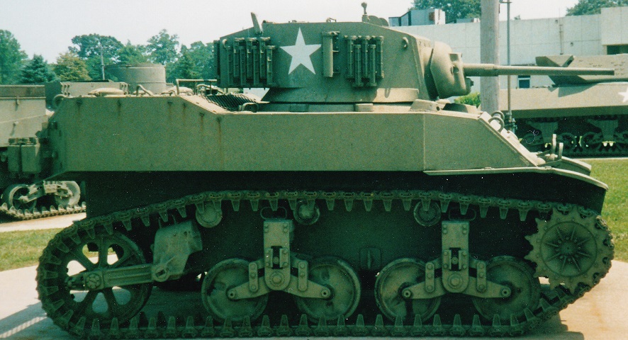
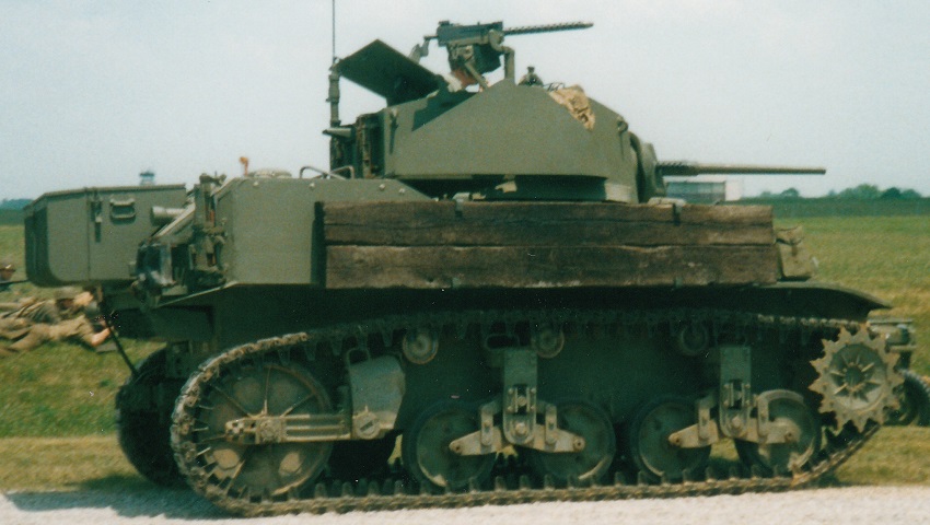
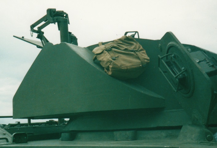
The sloping front hull plate featured on the M5 and M3A3 Stuarts can be seen above the front fenders on this tank. The characteristic vertical hull sides and raised rear decking that allowed room for the twin Cadillac engines mark this vehicle as an M5. The mount for the .30cal anti-aircraft machine gun can be seen on the turret rear, behind the group of track grousers stowed on the turret. The assistant driver's hatch is open, and although a better arrangement than that found in the M3 Stuart, it is obvious how easy it was for the hatches to be fouled by turret fixtures, especially the 37mm gun. (Picture from Development of Armored Vehicles, volume 1: Tanks.)
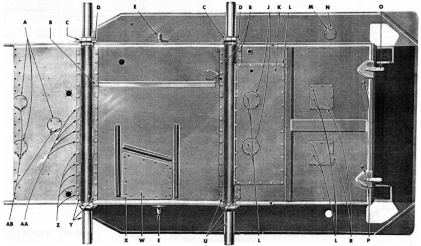
The various access ports and covers in the hull underside are detailed here. The floor escape hatch is W. The two bogie axles (Y and U) can also be seen with the suspension bogies removed. (Picture from ORD 7, 8-9 SNL G-103 Vols. II & VIII.)
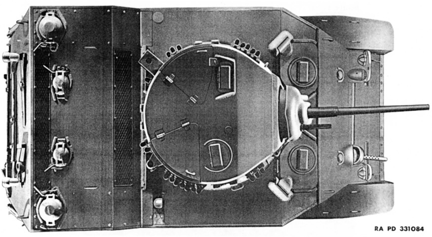
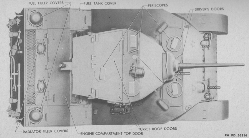
All of the crew's doors and the shape of the turret can be seen in this overhead view. (Picture from ORD 7, 8-9 SNL G-103 Vols. II & VIII.)
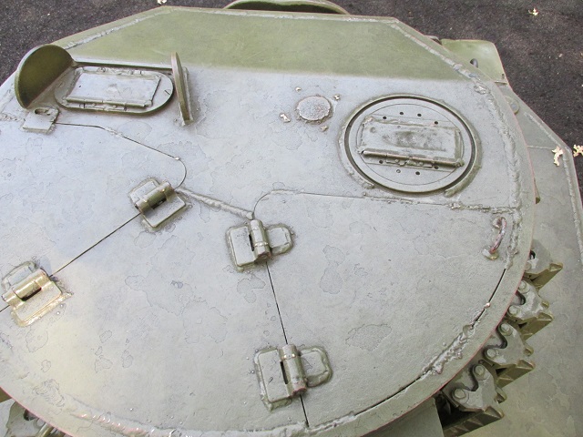
The roof doors for the gunner and commander can be seen on the turret's left and right, respectively. The commander had a rotating periscope M6 in front of his door, which was the same model used by the drivers, while the gunner had a nonrotating periscope M4 shielded between two guards.
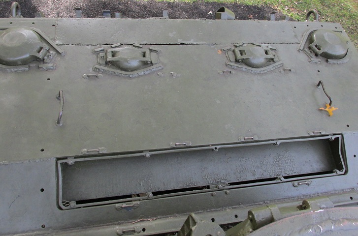
The rear deck is shown here. The outer filler covers were for fuel while the inboard ones were for the engines' radiators. Mesh screens would have covered the air inlets directly behind the turret and behind the radiator fillers, the latter of which is now covered by a solid plate.
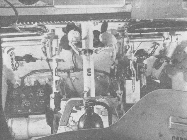
An overview of the drivers' compartment is given from the turret. The turret basket is in the bottom foreground, the turret ring gearing can be seen near the top, and the fixed fire extinguisher is mounted just ahead. (Picture from FM 17-68 Crew Drill, Light Tank M5 Series.)

The bow machine gun is shown here, with its ammunition box and feed empty of ammunition. The knock-out sight plug was attached by a chain to the hull interior, and the machine gun was aimed simply by adjusting the tracer stream and impacts. The portable fire extinguisher is visible in the lower left corner. (Picture from TM 9-732 Light Tanks M5 and M5A1.)
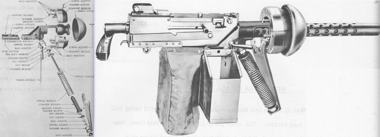
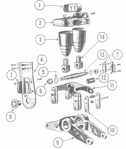
The caliber .30 ball mount D59830 is seen in an exploded view on the left and assembled with the machine gun mounted on the right. A caliber .30 ammunition box M1 and an expended case bag were supported by the mount, and an equilibrator spring helped to counterbalance the cradle, which attached to the machine gun's front mounting holes. (Picture from Weapon Mounts for Secondary Armament.)
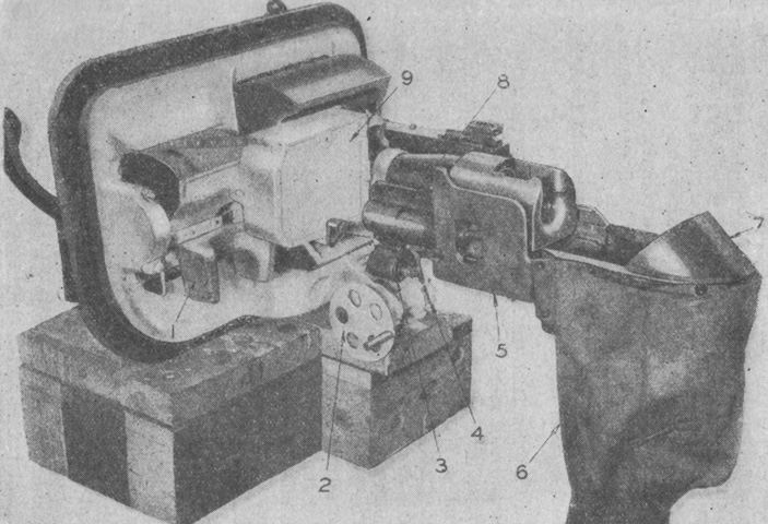
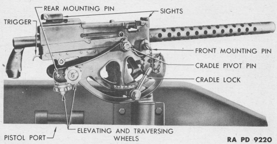
The combination gun mount M23 is seen from the left rear. 1. Head rest. 2. Elevating handwheel. 3. Solenoid firing device. 4. Trigger actuating mechanism. 5. Left guard. 6. Empty case bag. 7. Empty case deflector. 8. Closing spring housing. 9. Machine gun ammunition. (Picture from FM 17-68 Crew Drill, Light Tank M5 Series.)
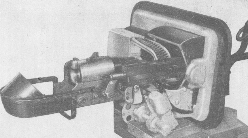
The opposite side of the gun mount M23 is pictured, with the machine gun and its ammunition present. (Picture from FM 17-68 Crew Drill, Light Tank M5 Series.)
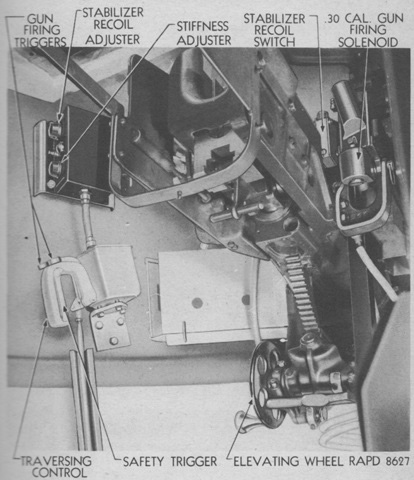
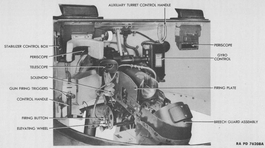
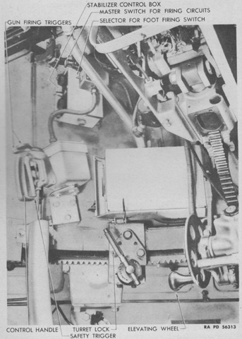
The gunner's controls can be seen in this image. To fire the gun electrically, the safety trigger was squeezed, then the triggers on top of the traversing control were depressed. (Picture from TM 9-732 Light Tanks M5 and M5A1.)
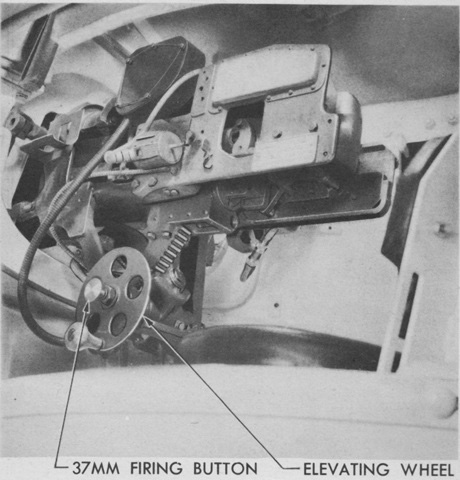
A closer look at the elevation wheel from the gunner's side of the turret is given here. The 37mm firing button on the elevation wheel was for firing the gun manually, which also required the safety trigger to be squeezed. (Picture from TM 9-732 Light Tanks M5 and M5A1.)
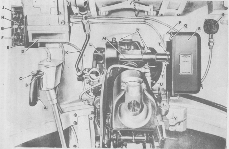
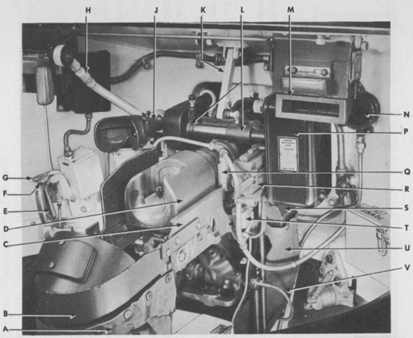
This diagram highlights the gunner's controls, gun mount, and stabilizer. A. Safety trigger. B. Cal. .30 machine gun firing trigger. C. 37mm gun firing trigger. D. Gunner's periscope. E. Control box. F. Stiffness adjuster. G. Switch. H. Pilot light. J. Recoil adjuster. K. Periscope parallel linkage. L. Mounting bracket and gear box. M. Mounting shaft. N. Grease fittings. P. Multi-prong connector. Q. Dust shield. R. Gyro control. S. Oil reservoir. T. Gyro control mounting bolts. U. Recoil switch. V. Combination gun mount. (Picture from TM 9-732 Light Tanks M5 and M5A1.)
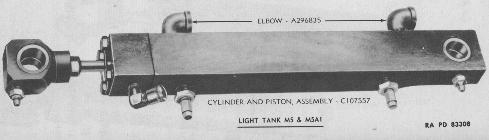
Hidden from view in the above images, the stabilizer cylinder and piston assembly is shown here. (Picture from TM 9-1334 Ordnance Maintenance--Stabilizers.)
The manual traverse controls were located at the rear of the turret. 1. Manual traverse crank. 2. Clutch lever. 3. Gunner's seat. 4. Radio. (Picture from FM 17-68 Crew Drill, Light Tank M5 Series.)
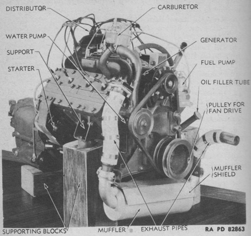
One of the twin L-head engines is shown here. The fan end of the engines was considered the front, even though it faced to the rear of the tank, so this angle is the engine's right front. It had a bore and stroke of 3.5" (8.9cm) and 4.5" (11cm), respectively, for a total displacement of 346in³ (5,670cm³). It had a compression ratio of 7.06:1, and weighed 1300lb (590kg) when attached to its transmission and accessories. (Picture from TM 9-732 Light Tanks M5 and M5A1.)
The engines are shown here installed with the rear deck and radiators removed. Note that they were not mounted in a parallel manner. (Picture from TM 9-732 Light Tanks M5 and M5A1.)
A Hydramatic transmission is mounted to one of the engines in this picture. No clutch pedal was required thanks to the fluid coupling of the automatic transmission. In the tank, the fluid coupling end was considered the front, and the propeller shaft end was considered the rear. (Picture from TM 9-732 Light Tanks M5 and M5A1.)
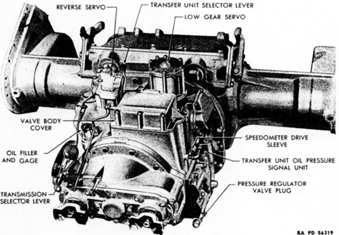
A cross-section of the Hydramatic transmission is labeled here. A. Screw. B. Cover, assembly. C. Torus, assembly. D. Torus, Assembly. E. Nut. F. Spring. G. Flywheel, assembly. H. Seal, assembly. J. Cover, assembly. K. Shaft, assembly. L. Shaft, assembly. M. Case, assembly. N. Gear. O. Carrier, assembly. P. Gear, assembly. R. Band, assembly. S. Drum, assembly. T. Spring. U. Plate. V. Piston. W. Drum, assembly. X. Sleeve, assembly. Y. Drum, assembly. Z. Piston. AA. Plate. BB. Band, assembly. CC. Spring. DD. Plate. EE. Plate. FF. Pin. GG. Drum, assembly. HH. Gear, assembly. JJ. Carrier, assembly. KK. Pinion. LL. Screw. MM. Flange. NN. Gear. OO. Gear. PP. Carrier, assembly. RR. Gear, assembly. SS. Shaft, assembly. TT. Retainer. UU. Bearing, assembly. VV. Sear, assembly. WW. Screw. XX. Washer. YY. Screw. ZZ. Pump, assembly. AB. Pan. AC. Pipe, assembly. AD. Seal. AE. Screen, assembly. AF. Bolt. AG. Nut. AH. Ring. AJ. Seal. AK. Gasket. AL. Plug. AM. Gasket. AN. Screw. AO. Cover. AP. Cooler, assembly. AR. Servo, assembly. AS. Servo and oil pump assembly. AT. Cap, assembly. (Picture from TM 9-1727C Ordnance Maintenance--Hydra-matic Transmission and Propeller Shafts for Light Tanks M5, M5A1, and 75-mm Howitzer Motor Carriage M8.)
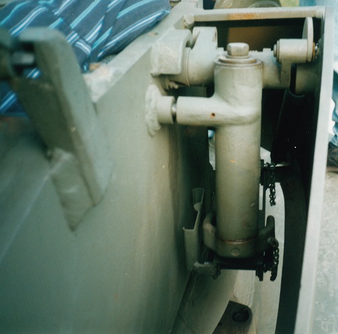
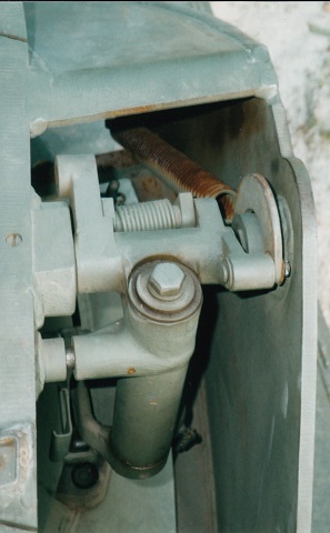
A detailed image of the front-mounted transfer unit is shown here. This assembly was connected by the universal joints at the bottom of the image to the propeller shafts that came from the transmissions and combined the two power flows into one. It also provided a two-speed hydraulic-controlled gear reduction. (Picture from TM 9-1727D Ordnance Maintenance--Transfer Unit for Light Tanks M5, M5A1, and 75-mm Howitzer Motor Carriage M8.)
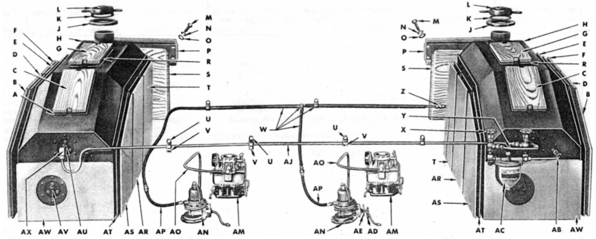
The fuel tanks were secured in the sponsons via wood and paper spacers (seen on the top, rear, and sides of each tank). Note the two fuel shut-off valves (X); the M5A1 combined their function into a single valve. (Picture from ORD 7, 8-9 SNL G-103 Vols. II & VIII.)
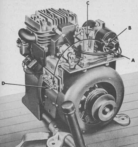
The 6-pole auxiliary generator was powered by a single-cylinder, 4-cycle, air-cooled gasoline engine that produced 1.6 horsepower at 2,300rpm. Bore and stroke were 2.3125" and 2.25" (5.7838cm and 5.72cm), respectively. The letters refer to connection points used when starting the engine with the battery nearly or completely discharged. (Picture from TM 9-732 Light Tanks M5 and M5A1.)

A 10lb (4.5kg) fixed fire extinguisher was secured to the bulkhead with tubes leading to the engine compartment to suffocate fires there. A portable 4lb (1.8kg) fire extinguisher was strapped behind the transfer unit in the drivers' compartment. (Picture from TM 9-732 Light Tanks M5 and M5A1.)
From this angle, there is little apparent difference between the M5A1 and the previous version. (Picture from TM 9-732 Light Tanks M5 and M5A1.)
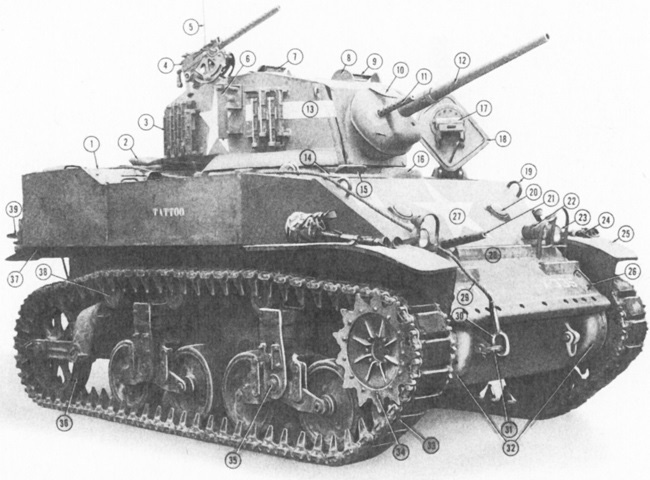
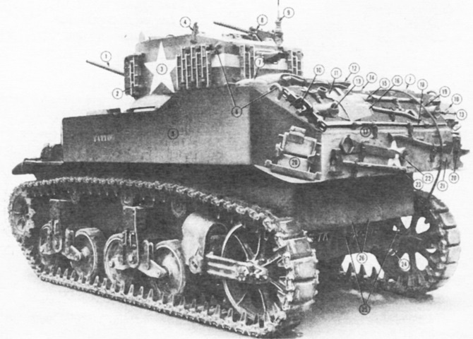
1. Rear deck. 2. Tarpaulin. 3. Grousers. 4. Cal .30 MG. 5. Radio antenna. 6. AA cal .30 MG mount. 7. Commander's periscope. 8. Periscope shield. 9. Gunner's periscope. 10. Gun shield. 11. Cal .30 coaxial MG. 12. 37-mm gun. 13. Turret. 14. Bog hatch. 15. Bog periscope. 16. Ventilator. 17. Driver's periscope. 18. Driver's hatch. 19. Lifting eye. 20. Knockout sight plug. 21. Cal .30 MG. 22. Siren. 23. Headlamp. 24. MG mount. 25. Mudguard. 26. Handle. 27. Front slope plate. 28. Splash shield. 29. Tow cable. 30. Shackle. 31. Clevis. 32. Final drive housing. 33. Track. 34. Sprocket. 35. Suspension unit. 36. Idler. 37. Air cleaner access. 38. Support roller. 39. Spare track block. (Picture from Light Tank Installations M5A1.)
The new turret on the M5A1 is shown here. A radio bustle was incorporated, and the AAMG mount has been moved to the turret's right-hand side. The pistol ports on this tank have also been omitted, and a ventilator has been added between the drivers directly below the gun shield.
The elongated turret shape can be easily seen in this top view. (Picture from TM 9-732 Light Tanks M5 and M5A1.)
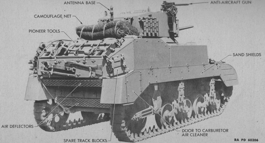
Sand shields are fitted to this tank, and the full complement of external stowage is present. (Picture from TM 9-732 Light Tanks M5 and M5A1.)
1. 37-mm gun. 2. Grousers. 3. Turret. 4. Hatch lock. 5. Sponson. 6. Lifting eyes. 7. Fuel filler cover. 8. .30 cal machine gun. 9. Radio antenna. 10. Track jack. 11. Pick-mattox. 12. Tarpaulin. 13. Tail lamp. 14. Radiator filler cover. 15. Pick-mattox handle. 16. Shovel. 17. Bustle. 18. Bar. 19. Tow cable. 20. Spare track block. 21. Axe. 22. Idler wrench. 23. Sledge. 24. Shackle and clevis. 25. Exhaust pipes. 26. Rear engine comp. doors. (Picture from Light Tank Installations M5A1.)
Parts of the bracket mount M20 are labeled in this image. Very few M5A1s featured pistol ports on the turret. (Picture from TM 9-732 Light Tanks M5 and M5A1.)
Details of the relocated turret machine gun mount can be seen in this image. Grousers are stowed on the turret, and the commander's periscope is raised. The turret spotlight is visible behind the commander's periscope.

This tank features the late-production stowage box on the hull rear, but lacks the shield found around the antiaircraft machine gun. T36E6 parallel grouser tracks are mounted. The filler covers in front of the stowage box were for the engines' radiators, while those near the hull side edges were for fuel.
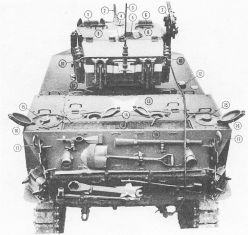
This tank lacks the rear stowage box. 1. Gunner's periscope. 2. 37-mm gun. 3. Antenna. 4. Ventilator. 5. Rear vision periscope. 6. Commander's periscope. 7. .30 cal AA machine gun. 8. Commander's hatch. 9. Gunner's hatch. 10. Lifting eyes. 11. Flag set. 12. Fire remote control. 13. Engine comp. top door. 14. Cooling system filler caps. 15. Fuel filler caps. 16. Fuel filler cap covers. 17. Lifting eyes. 18. Air intake grill. 19. Bustle. (Picture from Light Tank Installations M5A1.)
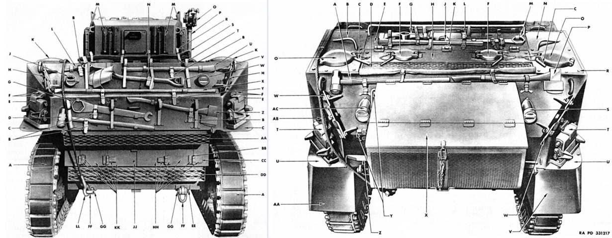
The difference in rear stowage between a tank without (left) and with (right) the rear stowage box is illustrated here. The legend for the left image is: A. Track, assembly (rubber). B. Strap. C. Guard. D. Sledge, w/handle. E. Bracket. F. Screw. G. Wrench. H. Clamp. J. Light, assembly. K. Cover. L. Mattock, pick, w/o handle. M. Grouser, assembly. N. Strap. O. Cradle, assembly. P. Bracket, assembly. R. Strap. S. Tarpaulin. T. Strap. U. Handle. V. Shovel. W. Light, assembly. X. Crowbar. Y. Strap. Z. Ax [sic]. AA. Deflector, w/baffle and screen, assembly. BB. Hinge. CC. Hinge. DD. Deflector, w/baffles and screen, assembly. EE. Bracket. FF. Shackle. GG. Pin. HH. Door, assembly. JJ. Screw; nut; retainer. KK. Door, assembly. LL. Cable.
The legend for the right image is: A. Sledge, w/handle. B. Roof, assembly. C. Pin, assembly. D. Screen, assembly. E. Door, assembly. F. Cover. G. Mattock, pick, w/o handle. H. Roof, assembly. J. Handle. K. Hinge. L. Strap. M. Wrench. N. Roof, assembly. O. Cover. P. Axe [sic]. R. Screw. S. Lamp, assembly. T. Bracket. U. Guard. V. Sandshield, assembly. W. Clamp. X. Box, assembly. Y. Crank, assembly. Z. Crowbar. AA. Sandshield, assembly. AB. Cable. AC. Light, assembly. (Picture from ORD 7, 8-9 SNL G-103 Vols. II & VIII.)
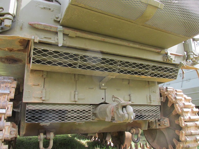
The rear of the tank was home to two different sets of air deflectors. The engine exhausts, marked by dark discoloration, were routed through the lower screens. The upper screens, able to be hinged upwards out of the way for maintenance, were for the engine cooling fans. Access doors to the rear of the engine compartment can also be seen above the towing pintle.
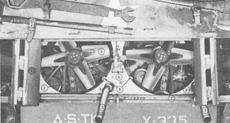
The rear engine compartment doors have been opened in this image. 1. Rear door. 2. Fan drive belt. 3. Exhaust pipe. 4. Fan blade. 5. Oil can. 6. Oil filler caps. 7. Belt tension adjusting tools. 8. Fuel pump. (Picture from Light Tank Installations M5A1.)
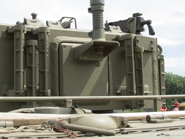
The removable plate dominates the rear of the turret, and track grousers are stowed on each side of this plate. Details of the antenna mount and cable can be discerned as well.
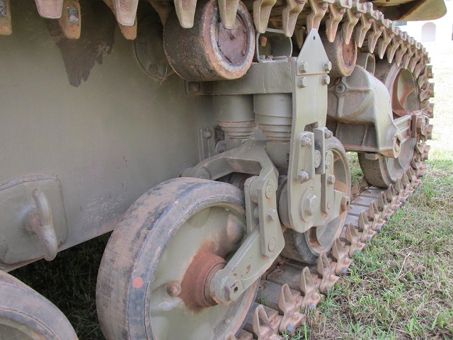
The rear suspension bogie and trailing idler assemblies are highlighted in this image. The idler had a horizontal volute spring under its protective bracket, and a track skid was mounted on the bracket itself. The suspension bogies also had track skids mounted to the tops of their brackets. There was a hook welded to the lower hull between the suspension bogies on both sides of the tank.
An exploded view of a suspension bogie is shown here. 1. Skid. 2. Bracket. 3. Volute springs. 4. Side plate. 5. Spring clip. 6. Gudgeon roller. 7. Roller guides. 8. Axle cap. 9. Wheel arms. 10. Vertical links. 11. Rocking link. 12. Bushing. 13. Bogie gudgeon. 14. Volute spring plugs. (Picture from Light Tank Installations M5A1.)
Parts of a rubber track block are diagrammed in this image. The rubber bushings on the track pins imparted some tension to adjacent track blocks. 1. Track shoe. 2. Track pins. 3. Bronze spring. 4. Rubber bushings. 5. Connections. 6. Wedge nut. 7. Wedge. (Picture from Light Tank Installations M5A1.)
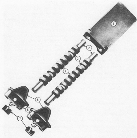
The new folding antiaircraft machine gun mount is shown on the left in an exploded view, and with the machine gun stowed behind its armor shield on the right. The gun could be brought into action from inside the turret by rotating the handle, and the gun could be locked in either the raised or lowered positions. A sprung yoke held the gun in the ready position, and when the yoke was released the gun was able to be swung free for aiming. As seen on the right, it was necessary to unload the gun and stow the ammunition box before lowering the gun. (Picture from Weapon Mounts for Secondary Armament.)
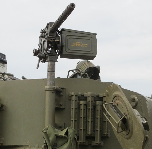
This vehicle sports the folding machine gun mount and armored shield.
Note the differences in the machine gun cradle compared to the earlier fixed mount.
The mount is swiveled down, but no machine gun is present.
The springs that helped with deploying and retracting the mount can be seen in this picture.
A cross-sectional view is shown here. Note the deflectors in contrast to the M5 above. (Picture from Catalogue of Standard Ordnance Items, 2nd edition 1944, volume 1.)
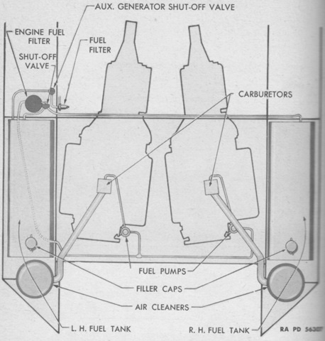
This schematic of the fuel system highlights the angle at which the twin engines were mounted relative to each other. The M5 had a shut-off valve for each fuel tank at the engine fuel filter, but the M5A1 combined these into a single shut-off valve. (Picture from TM 9-732 Light Tanks M5 and M5A1.)
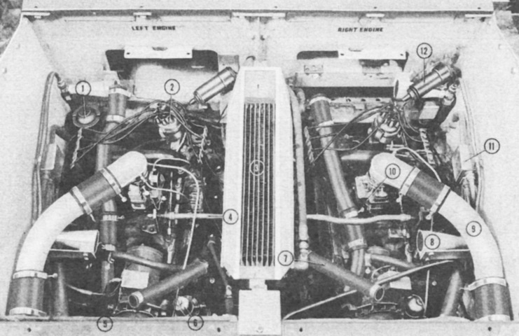
The engines are again shown here with the rear deck and radiators removed. 1. Auxiliary generator fuel filler cap. 2. Distributor cap. 3. Transfer unit oil cooler. 4. Carburetor linkage. 5. Generator. 6. Fuel pump. 7. Engine to radiator hose. 8. Fire extinguisher nozzle. 9. Air intake duct. 10. Carburetor. 11. Junction box. 12. Ignition coil. (Picture from Light Tank Installations M5A1.)

A schematic of the powertrain is provided here. 1. Final drive housing. 2. Accelerator pedal. 3. Differential. 4. Driver's steering levers. 5. Bog's steering levers. 6. Transfer unit manual control lever. 7. Transmission selector lever. 8. Throttle control rods. 9. Bog's back rest. 10. Manual control rods. 11. Transfer unit. 12. Front relay. 13. Propeller shafts. 14. Universal joints. 15. Intermediate relay cross shafts. 16. Transmission. 17. Oil filler caps. 18. Fluid couplings. (Picture from Light Tank Installations M5A1.)
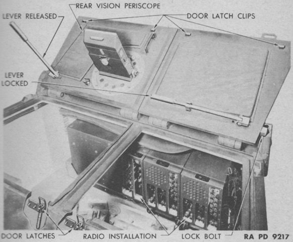
The turret doors are open, allowing a look into the rear of the turret. The usefulness of the new turret bustle in mounting the radio is obvious. The commander had a rotating periscope in his hatch door for rear vision in addition to a rotating periscope in the turret roof to his front, while the gunner had a fixed targeting periscope. The turret doors were locked by latches from the inside. Once handles attached to the latches were swung down, thereby releasing the latch clips, the doors could be swung open. They could be locked in the open position with the long levers at the bases of the doors. This lever could also be used to open or close the door from the inside, helping mitigate against the door's weight. (Picture from TM 9-732 Light Tanks M5 and M5A1.)
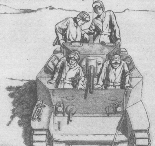
The cramped quarters in the light tank are apparent in this drawing of the crew taking their positions. The door for the assistant driver, when contrasted with the lack of the same in the M3 Stuart, was surely appreciated. A machine gun tripod is stowed on the right fender. (Picture from FM 17-68 Crew Drill, Light Tank M5 Series.)

The drivers' controls are depicted here. Each position had duplicated steering levers and accelerator pedals, but the assistant driver lacked an instrument panel and other controls. The transfer selector lever put the transmissions into neutral, forward, low, or reverse ranges. The transfer unit manual control lever allowed selection of driving or low range settings. When the transmission was in forward and the transfer unit was in drive, six forward speeds were possible. When the transmission was in forward and the transfer unit was in low, four forward speeds were possible. When the transmission was in low, there were two forward speeds possible with the transfer unit in both drive or low. (Picture from TM 9-732 Light Tanks M5 and M5A1.)
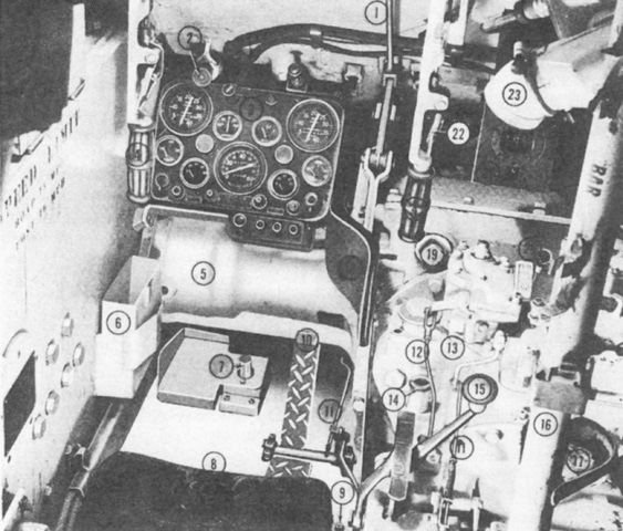
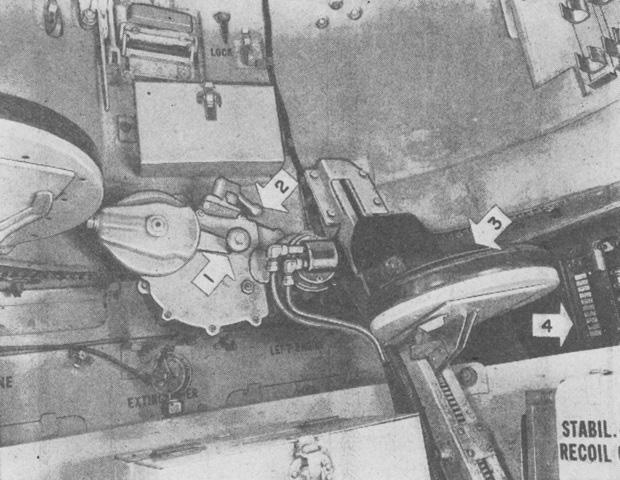
A closer look at the driver's position is the subject of this photograph. 1. Steering linkage. 2. Headlight plug. 3. Instrument panel. 4. Steering levers. 5. Differential housing. 6. Spare periscope head box. 7. Siren switch. 8. Driver's seat. 9. Drain valve. 10. Foot throttle. 11. Throttle control rods. 12. Manual control rod. 13. Transfer unit. 14. Oil filler tube cap. 15. Transmission selector lever. 16. Support post. 17. Fire extinguisher bracket. 18. Heat protection shield. 19. Brake band inspection plug. 20. Transfer unit manual control lever. 21. Pioneer compass. 22. Brake locking lever. 23. Ventilator. (Picture from Light Tank Installations M5A1.)
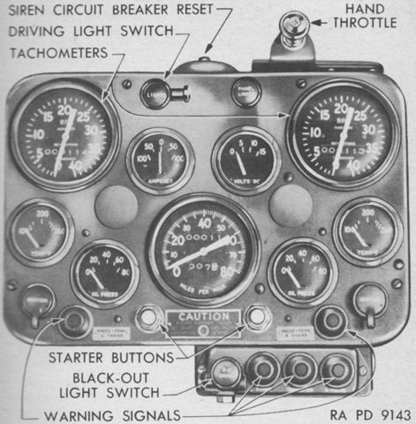
The early driver's instrument panel is shown in this picture. The instrument panel used in the M5 was identical except for the lack of warning signal lamps. On the top row to the right of the driving light switch is the panel light knob. The dials between the two tachometers are an ammeter on the left and a voltmeter on the right. Directly below the tachometers are temperature gages, and below and inside of these are oil pressure gages. The speedometer assembly is in the center, and ignition switches are at the bottom corners under the temperature gages. (Picture from TM 9-732 Light Tanks M5 and M5A1.)
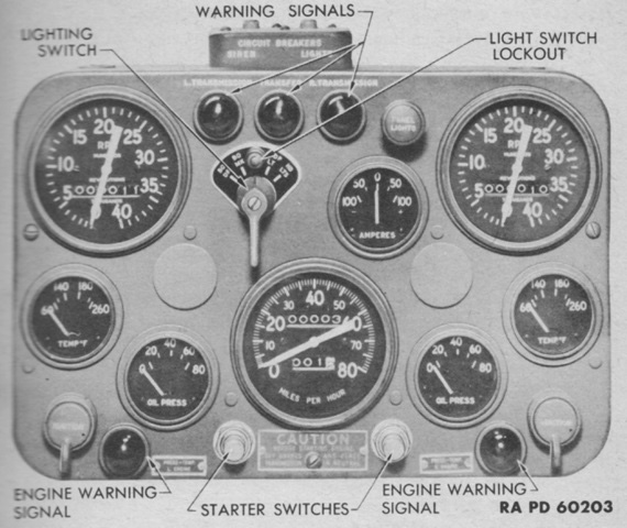
The later-production instrument panel is displayed here. The voltmeter is absent, the warning signal lamps have been integrated into the upper portion of the panel, and circuit breakers are available at the top. (Picture from TM 9-732 Light Tanks M5 and M5A1.)
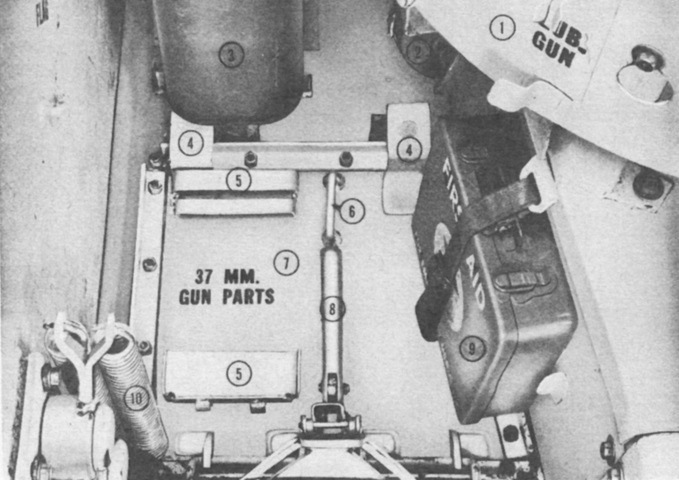
A hull floor escape hatch was located behind the assistant driver's seat. The front of the hatch was designed to drop first, followed by the rear after it was released from its two support levers. 1. Turret basket. 2. Decontaminator. 3. 5-gallon [20L] water can. 4. Hatch support levers. 5. Gun part box supports. 6. Handle. 7. Escape hatch. 8. Release lever. 9. First aid kit. 10. Bog seat spring. (Picture from Light Tank Installations M5A1.)
The front of the turret is shown in this image. (Picture from FM 17-68 C1 Crew Drill, Light Tank M5 Series.)
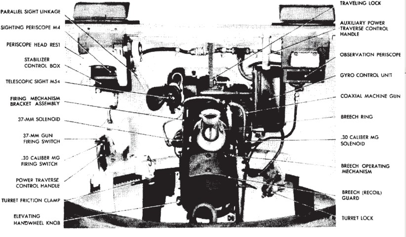
A view of the gun mount from the commander's side is provided. A. Empty cartridge bag--37-mm gun. B. Breech guard assembly. C. Breech operating mechanism. D. Breech ring--37-mm gun. E. Safety trigger. F. Electric firing lever--cal. .30 machine gun. G. Electric firing lever--37-mm gun. H. Gunner's periscope control linkage. J. Telescope. K. Traveling lock. L. Gear box and mounting bracket. M. Commander's periscope. N. Oil reservoir. P. Gyro control. Q. Recoil switch. R. Cal. .30 machine gun. S. Empty cartridge chute--cal. .30 machine gun. T. Firing solenoid--cal. .30 machine gun. U. Empty cartridge bag--cal. .30 machine gun. V. Hand firing cable. (Picture from TM 9-250 37-mm Gun M6, Mounted in Combat Vehicles.)
The gunner's side of the ordnance is shown here. (Picture from TM 9-250 37-mm Gun M6, Mounted in Combat Vehicles.)

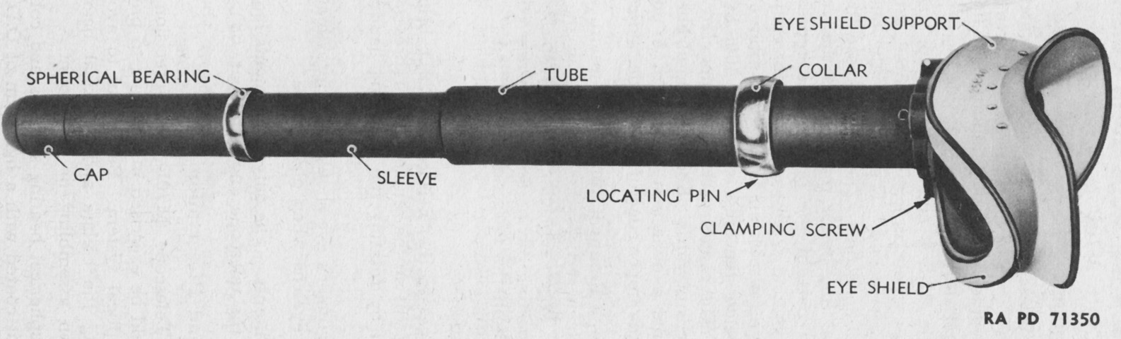
The rear of the gunner's periscope M4A1 is labeled in this picture. Compared to the earlier periscope M4, the M4A1 differed by having a reflection-reducing film on the optics and using the instrument light M30 to illuminate the reticle for night operations. Cross lines were still etched on the horizontal windows for emergency rough sighting. The telescope M40A2 was a 1.44x erect image type with a 9° field of view mounted on the right side of the periscope body between the horizontal windows. Adjustment knobs for boresighting the telescope are visible on the lower right of the periscope body. (Picture from TM 9-250 37-mm Gun M6, Mounted in Combat Vehicles.)
The M70D telescope was a 3x straight tube telescope with a 12°19' field of view. (Picture from TM 9-250 37-mm Gun M6, Mounted in Combat Vehicles.)
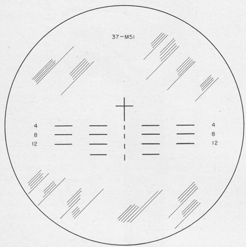
The reticle patterns for the telescopes M70D and M40A2 were the same, and were based upon the armor-piercing capped projectile M51. The cross was at zero range or deflection, and was used for boresighting. Each part of the broken vertical line at the center of the reticle represented 200 yards (180m) range, and the broken horizontal lines therefore represented 400, 800, 1,200, and 1,600 yards (370, 730, 1,100, and 1,500m), as denoted by the numbers marking hundred of yards. The horizontal lines and spaces each represented deflections of 5 mils. (Picture from TM 9-250 37-mm Gun M6, Mounted in Combat Vehicles.)
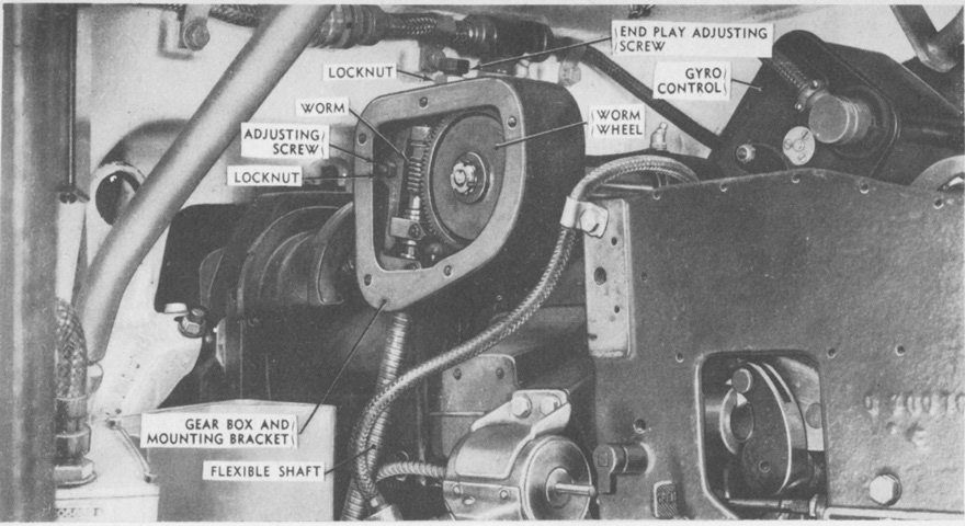
The cover of the stabilizer gear box has been removed, revealing its interior parts. (Picture from TM 9-250 37-mm Gun M6, Mounted in Combat Vehicles.)
The firing controls of the M5A1 were similar to those of the M5. (Picture from TM 9-732 Light Tanks M5 and M5A1.)
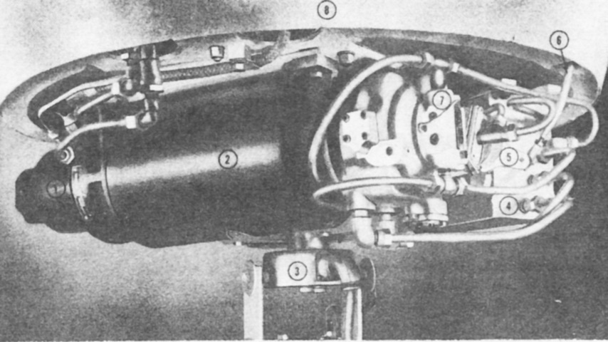
The stabilizer and turret traverse hydraulic pumps on the underside of the turret basket are seen here. 1. Stabilizer oil pump. 2. Electric motor. 3. Collector ring terminal box. 4. Oil pot. 5. Control lever. 6. Connecting rod--control handle to pump. 7. Traverse pump. 8. Basket. (Picture from Light Tank Installations M5A1.)
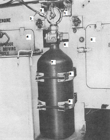
Further features of the fixed fire extinguisher are labeled in this more detailed view. 1. Control handle. 2. Wire key. 3. Remote control handle. 4. Right engine bulkhead door. 5. Left engine bulkhead door. 6. Lead seal. 7. Extinguisher case. 8. Mounting clamps. (Picture from Light Tank Installations M5A1.)

The difference in the hull designs between the two generations of Stuart tanks is well illustrated here. A good comparison can also be made between the positions of the telescopes in the combination gun mounts M44 and M23, with the the newer mount placing the telescope higher.
