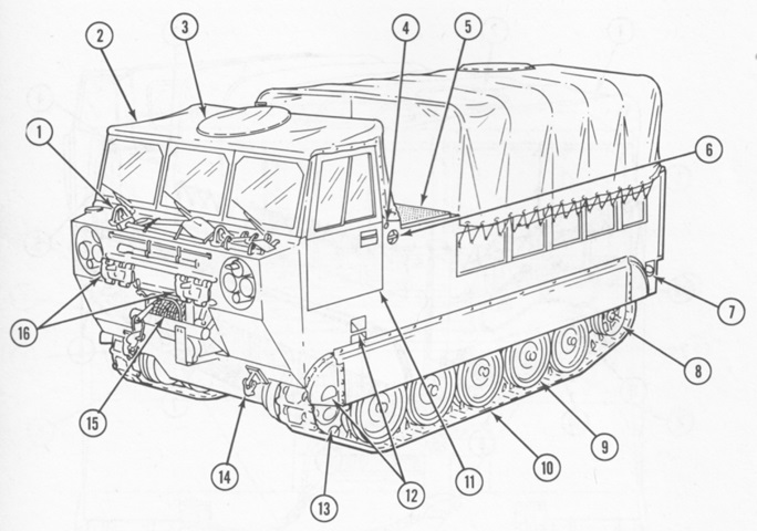
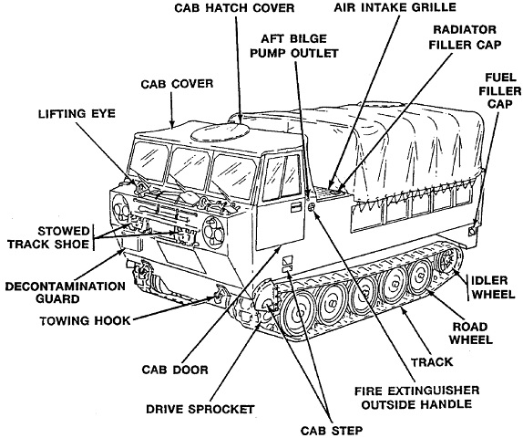
Cargo Carrier M548.
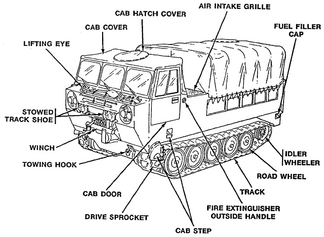
The vehicle is shown here from the left front with the cargo compartment cover installed. Its M113A1 parentage can be seen in the running gear. 1. Lifting eye. 2. Cab cover. 3. Cab hatch cover. 4. Aft bilge pump outlet. 5. Air intake grille. 6. Fire extinguisher outside handle. 7. Fuel filler cap. 8. Idler wheel. 9. Road wheel. 10. Track. 11. Cab door. 12. Cab step. 13. Drive sprocket. 14. Towing eye. 15. Winch. 16. Spare track shoe. (Picture from TM 9-2350-247-10 Driver's Operation and Maintenance Manual Carrier, Cargo, Tracked, 6-ton: M548 (2350-00-078-4545).)
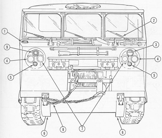
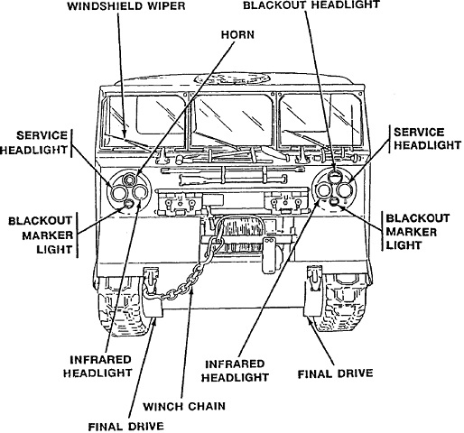
1. Antenna mounting base. 2. Windshield wiper. 3. Blackout headlight. 4. Service headlight. 5. Blackout marker light. 6. Final drive. 7. Infrared headlight. 8. Winch chain. 9. Horn. (Picture from TM 9-2350-247-10 Driver's Operation and Maintenance Manual Carrier, Cargo, Tracked, 6-ton: M548 (2350-00-078-4545).)
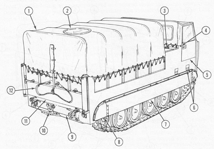
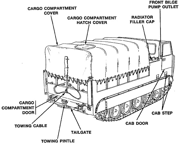
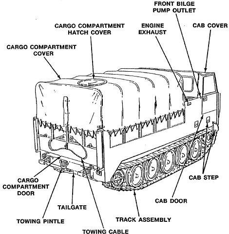
1. Cargo compartment cover. 2. Cargo compartment hatch cover. 3. Radiator filler cap. 4. Forward bilge pump outlet. 5. Cab door. 6. Cab step. 7. Track shroud. 8. Track cover. 9. Tailgate. 10. Towing pintle. 11. Cargo compartment door. 12. Towing cable. (Picture from TM 9-2350-247-10 Driver's Operation and Maintenance Manual Carrier, Cargo, Tracked, 6-ton: M548 (2350-00-078-4545).)
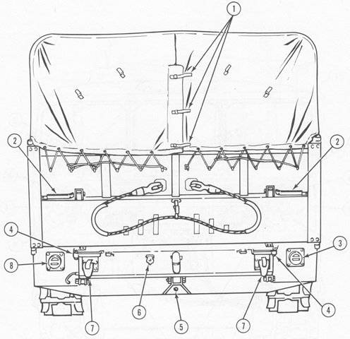
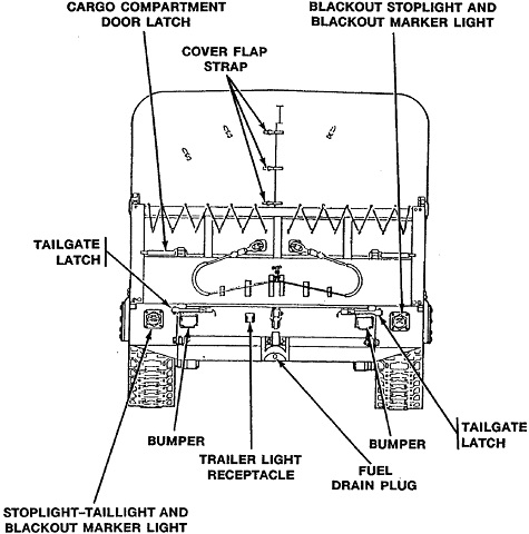
1. Cover flap strap. 2. Cargo compartment door latch. 3. Blackout stop light and blackout marker light. 4. Tailgate latch. 5. Fuel drain plug. 6. Trailer light receptacle. 7. Towing hook. 8. Stoplight-taillight and blackout marker light. (Picture from TM 9-2350-247-10 Driver's Operation and Maintenance Manual Carrier, Cargo, Tracked, 6-ton: M548 (2350-00-078-4545).)
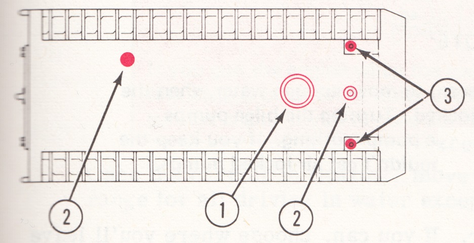
The bottom of the vehicle is sketched here 1. Hull access cover. 2. Drain covers. 3. Final drive recess drain plugs. (Picture from TM 9-2350-247-10 Driver's Operation and Maintenance Manual Carrier, Cargo, Tracked, 6-ton: M548 (2350-00-078-4545).)
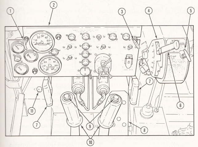
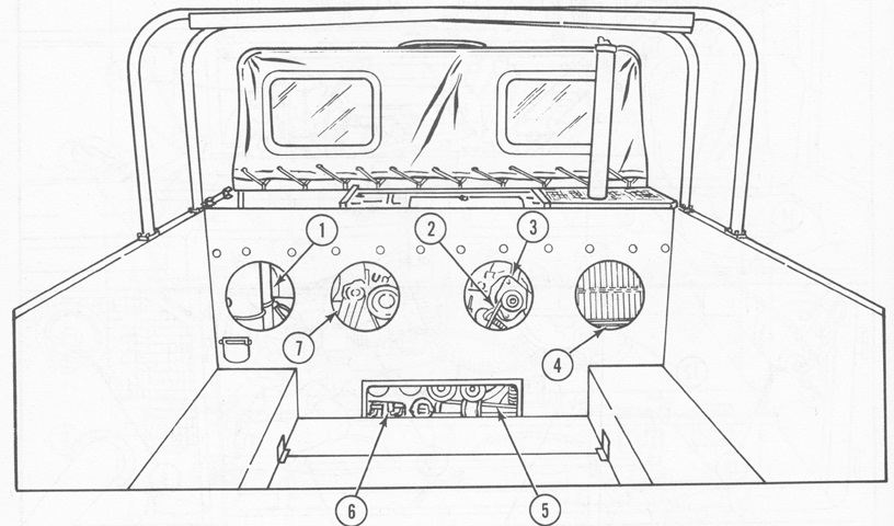
The driver's position is detailed in this drawing. 1. Fuel cutoff. 2. Instrument panel. 3. Hand throttle. 4. Range selector housing. 5. Winch power takeoff control. 6. Shift lever. 7. Pivot steer lever. 8. Accelerator pedal. 9. Brake lock button. 10. Differential steering lever. 11. Beam selecting switch. (Picture from TM 9-2350-247-10 Driver's Operation and Maintenance Manual Carrier, Cargo, Tracked, 6-ton: M548 (2350-00-078-4545).)
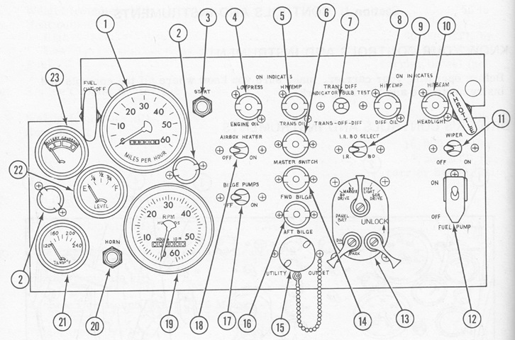
The driver's instrument panel is highlighted here. 1. Speedometer. 2. Panel light. 3. Start switch. 4. Engine low oil pressure warning light. 5. Transmission oil high temperature warning light. 6. Master switch ON indicator light. 7. Transmission-differential indicator bulb test switch (carriers after C-3500 only). 8. Differential oil high temperature warning light. 9. Infrared-blackout selector switch. 10. High beam ON indicator light. 11. Windshield wiper switch. 12. Fuel pump switch. 13. Driving lights switch. 14. Forward bilge pump ON indicator light. 15. Utility outlet. 16. Aft bilge pump ON indicator light. 17. Bilge pumps switch. 18. Air box heater switch. 19. Tachometer. 20. Horn switch. 21. Engine coolant temperature gage. 22. Fuel gage. 23. Battery-generator gage. (Picture from TM 9-2350-247-10 Driver's Operation and Maintenance Manual Carrier, Cargo, Tracked, 6-ton: M548 (2350-00-078-4545).)
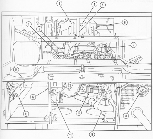
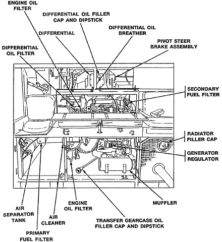
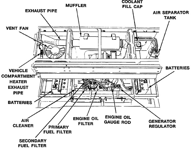
The engine compartment is seen here from above. The cab seats are at the top of the image, with the middle two raised to access the engine below. 1. Differential oil filter. 2. Engine oil filter. 3. Differential. 4. Differential and transfer gearcase oil filler can and dipstick. 5. Differential oil breather. 6. Pivot steer brake assembly. 7. Secondary fuel filter. 8. Radiator filler cap. 9. Exhaust pipe. 10. Generator regulator. 11. Engine oil filter. 12. Air cleaner. 13. Air separator tank. 14. Primary fuel filter. (Picture from TM 9-2350-247-10 Driver's Operation and Maintenance Manual Carrier, Cargo, Tracked, 6-ton: M548 (2350-00-078-4545).)
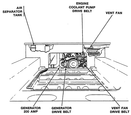
In carriers serial numbers CHX-1 through CHX-507 and C-1 through C-3500, the powerplant compartment rear bulkhead featured four circular and one rectangular access panels. 1. Air separator tank. 2. Generator drive belts. 3. Generator. 4. Radiator. 5. Rear fan drive belts. 6. Electric fuel pumps. 7. Engine oil filter. (Picture from TM 9-2350-247-10 Driver's Operation and Maintenance Manual Carrier, Cargo, Tracked, 6-ton: M548 (2350-00-078-4545).)
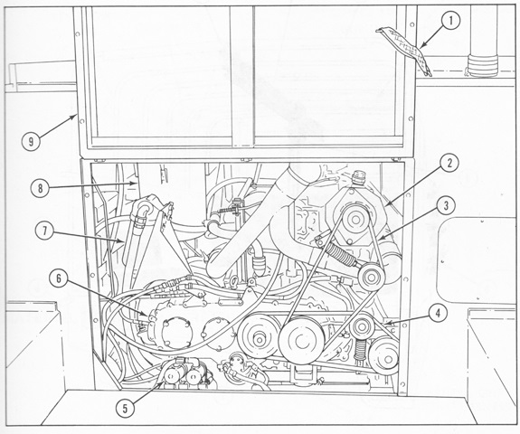
Later production and some rebuilt vehicles instead had a large hinged access panel and two rectangular access panels. 1. Retaining strap. 2. Generator. 3. Generator drive belts. 4. Rear fan drive belts. 5. Electric fuel pumps. 6. Transfer gearcase. 7. Engine oil filter. 8. Air cleaner. 9. Hinged power plant rear access panel. (Picture from TM 9-2350-247-10 Driver's Operation and Maintenance Manual Carrier, Cargo, Tracked, 6-ton: M548 (2350-00-078-4545).)
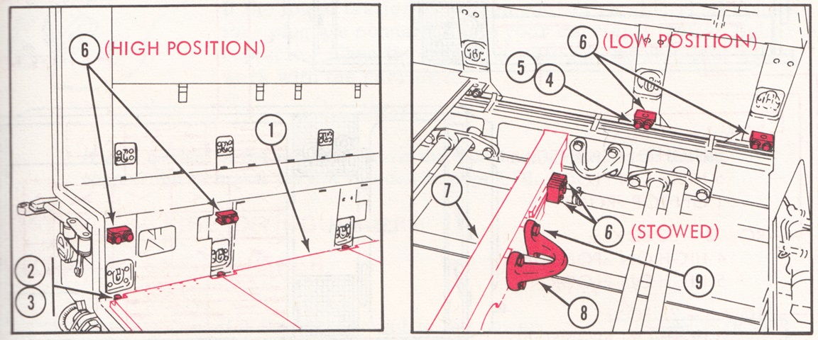
The two positions of the cargo compartment floor plates are shown here. The high position provided a wide area, while the low position allowed tall loads or legroom for a material handling crew seated in the rear. To change positions, the floor plates were removed, the floor plate support brackets fastened to the other position, then the floor plates were replaced. The high position used seven support brackets along each sponson, while the low position used four, with the remainder stowed under the floor on the hull crossmember. The lifting eyes could also be stowed under the floor. 1. Floor plates. 2. Screw. 3. Spacer. 4. Screw. 5. Washer. 6. Floor plate support bracket. 7. Hull crossmember. 8. Rear lifting eye. 9. Screw. (Picture from TM 9-2350-247-10 Driver's Operation and Maintenance Manual Carrier, Cargo, Tracked, 6-ton: M548 (2350-00-078-4545).)
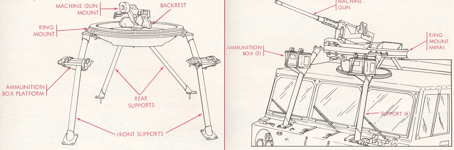
The machine gun mount M66 is shown on the left, with the ring mount M49A1 on the right. The M49A1 required a different mounting kit in order to use the 7.62mm machine gun M60, and could traverse 360°, elevate 80°, and depress the gun to -20°. The M66 kit weighed 380lb (170kg), compared to the M49A1's 475lb (215kg). With the gun mount installed, the front lifting eyes were removed and stowed under the cargo compartment floor plates. (Picture from TM 9-2350-247-10 Driver's Operation and Maintenance Manual Carrier, Cargo, Tracked, 6-ton: M548 (2350-00-078-4545).)
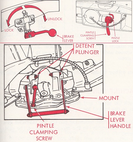
The top two images show the controls for the M66 machine gun mount. The brake lever halted traverse of the mount, and the pintle lock arrested traverse of the pintle. On the M49A1, illustrated in the bottom drawing, the brake lever handle was pulled up and back to traverse the mount; the brake lever handle could be held in place by the detent plungers. (Picture from TM 9-2350-247-10 Driver's Operation and Maintenance Manual Carrier, Cargo, Tracked, 6-ton: M548 (2350-00-078-4545).)
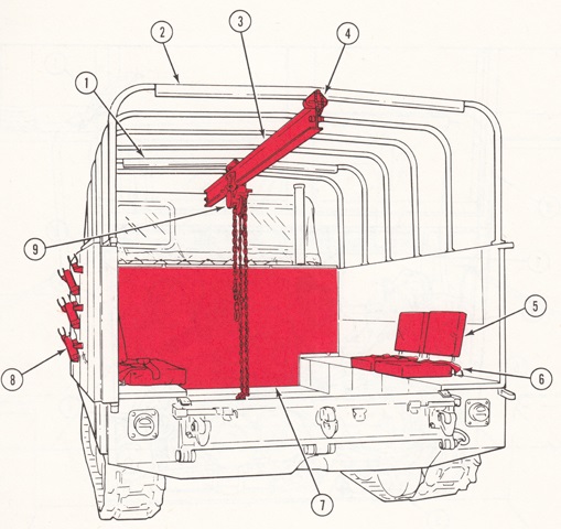
The material handling kit is diagrammed here. The kit provided space for four crew in the cargo compartment and weighed 148lb (67.1kg). The beam was 158.4" (402.3cm) long, and could lift up to 1,500lb (680kg) to a height of 96" (240cm). When lifting the heaviest capacity, the chain pull was 60lb (27kg). 1. Front support bow. 2. Rear support bow. 3. Hoist beam. 4. Beam support. 5. Seat. 6. Seat belt. 7. Plywood protector. 8. Rifle rack. 9. Chain hoist. (Picture from TM 9-2350-247-10 Driver's Operation and Maintenance Manual Carrier, Cargo, Tracked, 6-ton: M548 (2350-00-078-4545).)
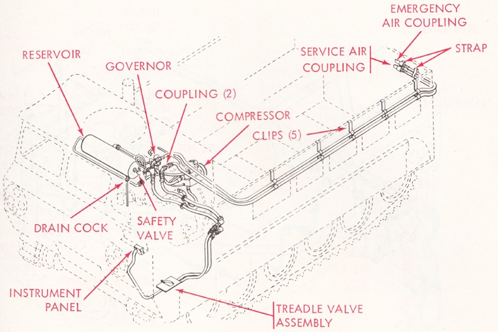
The air brake kit was installed when towing equipment that used air brakes. The kit weighed 90lb (40kg) and was governed to 85-105psi (6.0-7.37kg/cm²). The safety valve released at 150psi (10.5kg/cm²), and the low pressure warning activated at 60psi (4.2kg/cm²). (Picture from TM 9-2350-247-10 Driver's Operation and Maintenance Manual Carrier, Cargo, Tracked, 6-ton: M548 (2350-00-078-4545).)
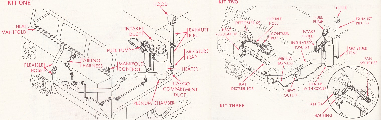
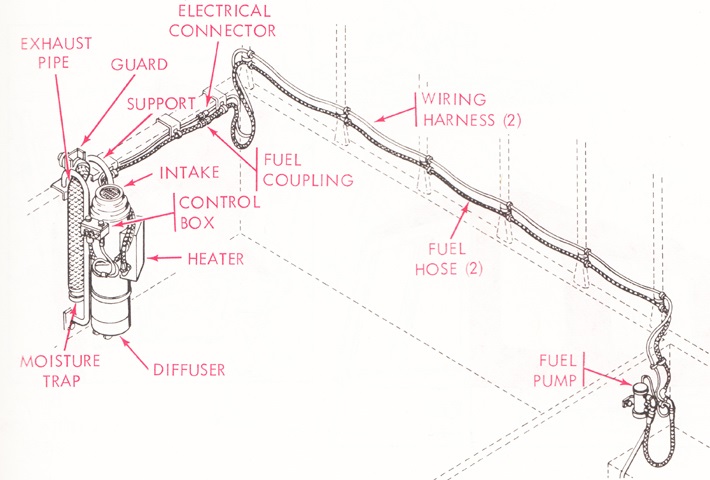
Three different types of cab (primary) heater kits were developed to provide heat to the cab occupants and defrost the windshield. Kit one ingested outside air via a duct in the power plant compartment, distributed the air through a tubular manifold that crossed the width of the cab below the windshield, and provided a duct that supplied heated air to the cargo compartment. Kit two took in air from a duct behind the driver's seat and had two defroster ducts, a separate cab heat distributor and regulator valve, and a separate duct for the driver's footwell. Kit three was similar to kit two, except that the regulator valve was deleted and two fans with individual on-off switches circulated cab air to the defroster ducts. The kits weighed 80lb (36kg), put out 60,000BTU/hr heat on high mode and 30,000BTU/hr on low mode, and used diesel fuel from the carrier. (Picture from TM 9-2350-247-10 Driver's Operation and Maintenance Manual Carrier, Cargo, Tracked, 6-ton: M548 (2350-00-078-4545).)
A primary personnel heater kit could also be installed in the cargo compartment when seats from the material handling kit were mounted. This weighed 55lb (25kg), also used the carrier's fuel, and provided identical heat output as the cab primary heater kit. (Picture from TM 9-2350-247-10 Driver's Operation and Maintenance Manual Carrier, Cargo, Tracked, 6-ton: M548 (2350-00-078-4545).)
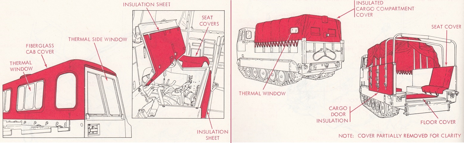
Secondary personnel heater kits could also be mounted on the cab and cargo compartment when the temperature dropped below -25°F (-32°C). The cab kit replaced the fabric cab cover with an insulated fiberglass cover and added thermal windows, cloth seat covers, and foam insulation sheets. The cargo compartment exchanged the fabric cargo compartment cover with an insulated fabric cover, and added plywood floor covers, cloth seat covers if the seats were installed, and foam cargo door insulation panels. The cab kit weighed 140lb (64kg), and the cargo compartment kit 85lb (39kg). (Picture from TM 9-2350-247-10 Driver's Operation and Maintenance Manual Carrier, Cargo, Tracked, 6-ton: M548 (2350-00-078-4545).)
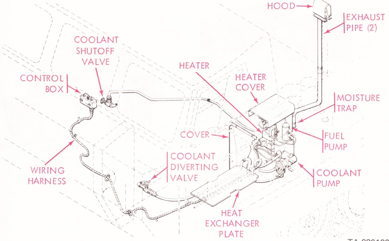
The engine coolant heater kit allowed the vehicle to be used in temperatures under -25°F (-32°C). The heat exchanger plate was for the batteries, which were located under the driver's seat. The kit weighed 59lb (27kg), used the carrier's fuel, and produced 16,000BTU/hr on the high setting and 5,500BTU/hr on low. (Picture from TM 9-2350-247-10 Driver's Operation and Maintenance Manual Carrier, Cargo, Tracked, 6-ton: M548 (2350-00-078-4545).)
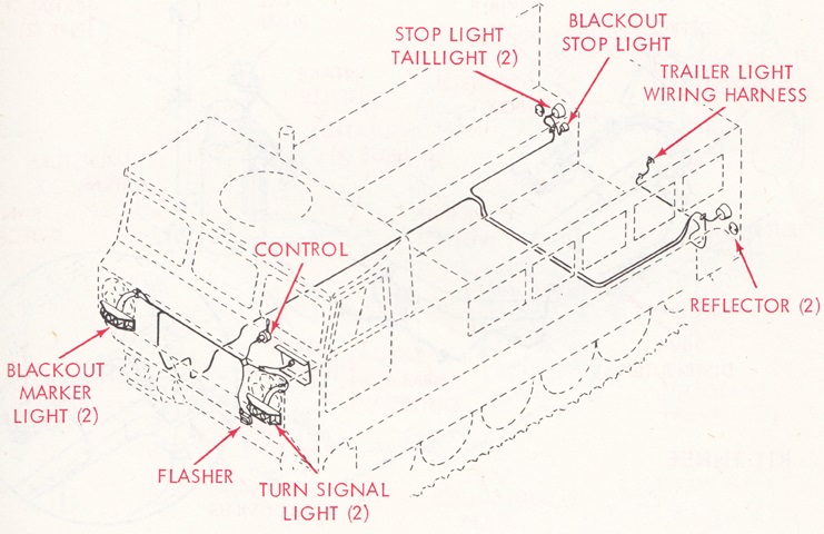
Used when required on roads, the turn signal kit added front signal lights and brackets, a control unit, a flasher, reflectors, and different taillights. (Picture from TM 9-2350-247-10 Driver's Operation and Maintenance Manual Carrier, Cargo, Tracked, 6-ton: M548 (2350-00-078-4545).)
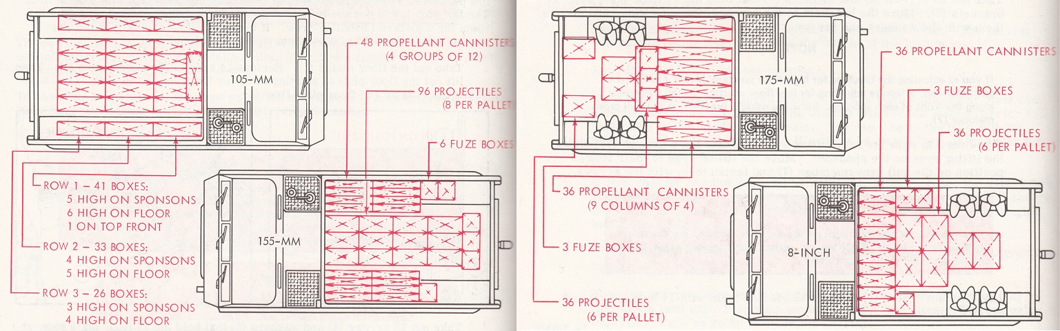
Loading charts for different artillery calibers are shown here. (Picture from TM 9-2350-247-10 Driver's Operation and Maintenance Manual Carrier, Cargo, Tracked, 6-ton: M548 (2350-00-078-4545).)
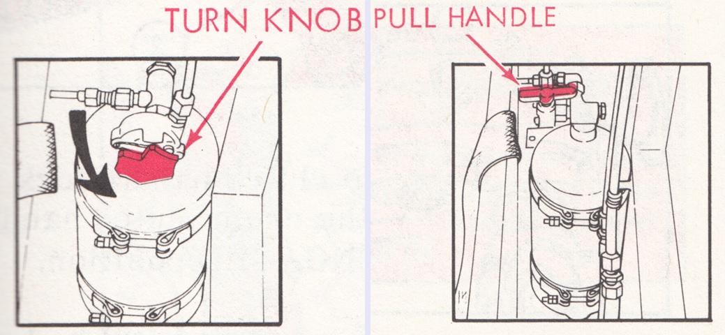
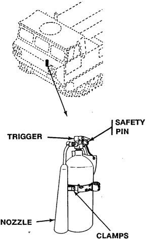
The fixed fire extinguisher cylinder for engine compartment fires was mounted to the driver's left rear. It could be actuated by the external handle behind the driver's door, or by using the control on the cylinder head, which could either be a knob or a pull handle. A portable fire extinguisher was stowed on the left side of the cab utility compartment. (Picture from TM 9-2350-247-10 Driver's Operation and Maintenance Manual Carrier, Cargo, Tracked, 6-ton: M548 (2350-00-078-4545).)
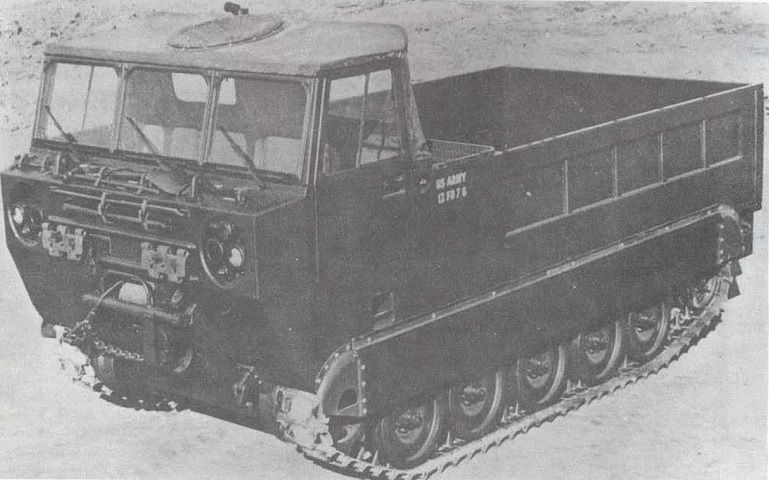
This vehicle has the cab cover installed, and a hatch cover can be seen in the top. Extra track shoes, tool stowage, and the front-mounted winch are placed between the headlight clusters on the hull front. (Picture from TM 55-2350-224-14.)
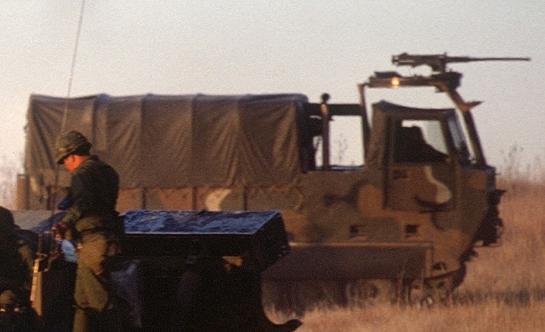
This vehicle has the covers installed on both the cab and the cargo compartment. The mount for the .50cal MG is positioned over the middle of the cab, and the engine's exhaust stack can be seen between the cab and the cargo compartment cover. (Picture taken 1 Dec 1978 by Anthony Edgeworth; available from the National Archives.)
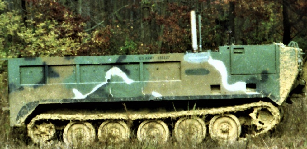
This vehicle is not fitted with either the cab or cargo compartment covers; the vehicle was 76" (190cm) tall to the top of the hull without the cab and windshield. The engine exhaust stack can still be seen. (Photo by Richard S. Eshleman.)
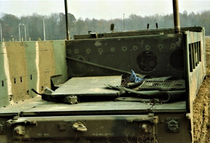
A view into the cargo compartment is provided here, thanks to the missing rear doors. The cargo compartment floor is mounted in the high position, and the early power plant compartment bulkhead can be seen with the round access holes. (Photo by Richard S. Eshleman.)
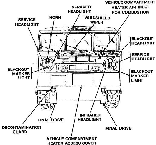
Details of the front of the M548A1 are drawn here. (Picture from TM 9-2350-247-10 C1 Operator's Manual for Carrier, Cargo Tracked, 6-ton M548A1 2350-01-096-9356 (EIC AEU) M548A3 2350-01-369-6081 (EIC AE9).)
A closer view of the front is provided in this image. (Picture from TM 9-2350-247-10 C1 Operator's Manual for Carrier, Cargo Tracked, 6-ton M548A1 2350-01-096-9356 (EIC AEU) M548A3 2350-01-369-6081 (EIC AE9).)
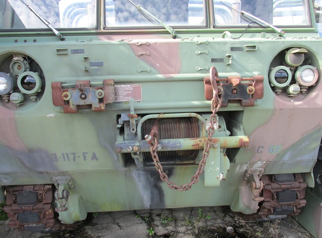
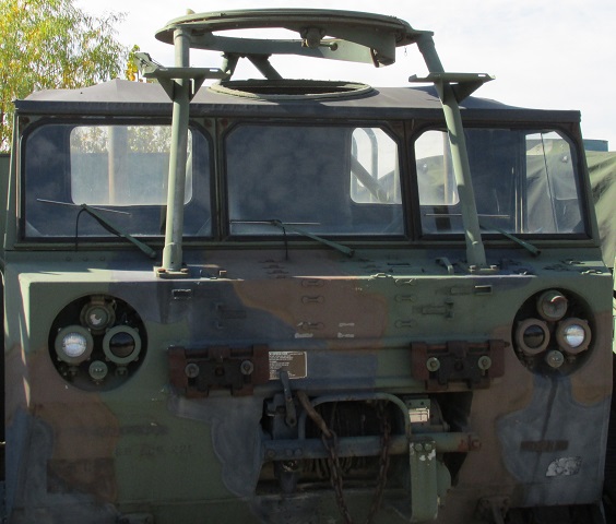
Details of the winch can be seen on this vehicle, which retains its full complement of headlights. Numerous footman loops are present on the hull, and brackets for tool stowage can be seen above the winch and under the center windscreen.
The rear entrance was a 2-piece affair. The bottom opened downward, while the upper section opened to either the left or the right. When the cargo compartment bed was at its lowest position, it was 26.5" (67.3cm) above the ground. (Picture from TM 9-2350-247-10 C1 Operator's Manual for Carrier, Cargo Tracked, 6-ton M548A1 2350-01-096-9356 (EIC AEU) M548A3 2350-01-369-6081 (EIC AE9).)
Further details of the rear are sketched here. (Picture from TM 9-2350-247-10 C1 Operator's Manual for Carrier, Cargo Tracked, 6-ton M548A1 2350-01-096-9356 (EIC AEU) M548A3 2350-01-369-6081 (EIC AE9).)
Access to the top of the engine compartment was still available in the cab. The driver's seat is at the top left of the drawing. (Picture from TM 9-2350-247-10 C1 Operator's Manual for Carrier, Cargo Tracked, 6-ton M548A1 2350-01-096-9356 (EIC AEU) M548A3 2350-01-369-6081 (EIC AE9).)
The stowage location of the portable fire extinguisher is revealed in this drawing. (Picture from TM 9-2350-247-10 C1 Operator's Manual for Carrier, Cargo Tracked, 6-ton M548A1 2350-01-096-9356 (EIC AEU) M548A3 2350-01-369-6081 (EIC AE9).)
The machine gun mount M66 is installed on this vehicle. The cab hatch cover is open, and a bracket for an ammunition box is present on each of the forward supports.

The ammunition box brackets are easier to see from this angle, and the substantial bolts that secure the supports to the hull can be seen at the base of the support in the foreground.
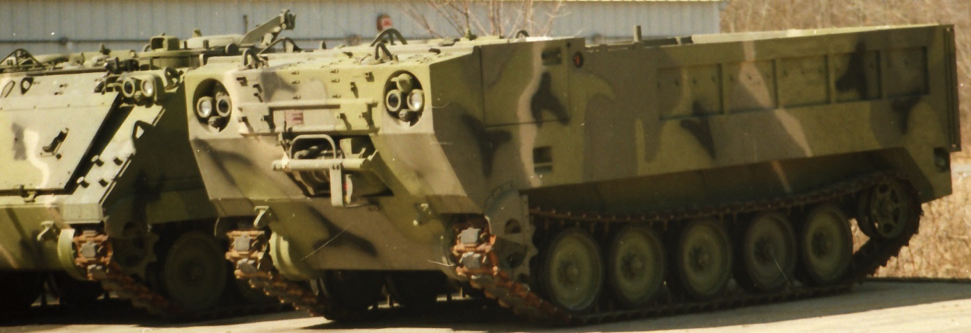
This vehicle is bereft of covers. The M548A1 was visually very similar to the M548, but the raised idler wheel on this machine indicates it is the former. (Photo by Richard S. Eshleman.)
The M548A3 can be compared with the vehicles above. Note the absence of the winch. (Picture from TM 9-2350-247-10 C1 Operator's Manual for Carrier, Cargo Tracked, 6-ton M548A1 2350-01-096-9356 (EIC AEU) M548A3 2350-01-369-6081 (EIC AE9).)
The front of the M548A3 is shown. (Picture from TM 9-2350-247-10 C1 Operator's Manual for Carrier, Cargo Tracked, 6-ton M548A1 2350-01-096-9356 (EIC AEU) M548A3 2350-01-369-6081 (EIC AE9).)
The RISE powerpack featured a different exhaust routing. (Picture from TM 9-2350-247-10 C1 Operator's Manual for Carrier, Cargo Tracked, 6-ton M548A1 2350-01-096-9356 (EIC AEU) M548A3 2350-01-369-6081 (EIC AE9).)
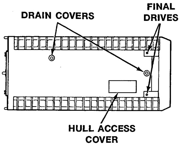
The underside of the hull and the changed access cover are shown here. (Picture from TM 9-2350-247-10 C1 Operator's Manual for Carrier, Cargo Tracked, 6-ton M548A1 2350-01-096-9356 (EIC AEU) M548A3 2350-01-369-6081 (EIC AE9).)
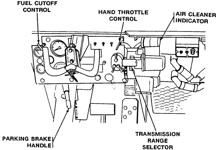
The driver's controls are sketched here, and can be contrasted with the earlier machines above. The headlight beam selector switch can be seen behind the parking brake handle, the brake pedal is to the left of the accelerator pedal, the personnel heater control box is to the right of the image above the ducting, and a steering wheel replaced the previous steering levers. (Picture from TM 9-2350-247-10 C1 Operator's Manual for Carrier, Cargo Tracked, 6-ton M548A1 2350-01-096-9356 (EIC AEU) M548A3 2350-01-369-6081 (EIC AE9).)
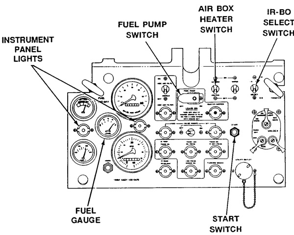
The driver's instrument panel is the subject of this drawing; the steering wheel would fit into the channel above the fuel pump switch. On the right of the panel, the driving lights switch is recognizable under the hand throttle. Between the airbox heater switch and the IR-BO select switch is the windshield wiper switch. A utility outlet is below left of the driving lights switch. From top to bottom under the airbox heater switch is the master switch on indicator light, the aft bilge pump on indicator light, the transmission oil high differential pressure indicator light, and the parking brake indicator light. Under the fuel pump switch is the bilge pump switch, and at the bottom is the the engine oil low pressure warning light. To the left of the fuel pump switch, from top to bottom, are the NBC air filter switch, NBC air filter on indicator light, forward bilge pump on indicator light, transmission oil high temp warning light, and the headlights high beam indicator light. The large dial to the left of the NBC air filter switch is the speedometer/odometer, and the dial below this is the tachometer; an instrument panel light is between these. The fuel gage is left of the speedometer and odometer, and the horn switch is directly below this. The fuel shutoff handle is to the upper left, and from top to bottom below this is the battery-generator gage, an instrument panel light, and the engine coolant temperature gage. (Picture from TM 9-2350-247-10 C1 Operator's Manual for Carrier, Cargo Tracked, 6-ton M548A1 2350-01-096-9356 (EIC AEU) M548A3 2350-01-369-6081 (EIC AE9).)
The powerplant compartment is sketched from the cargo compartment. The cargo compartment floor plates are absent. (Picture from TM 9-2350-247-10 C1 Operator's Manual for Carrier, Cargo Tracked, 6-ton M548A1 2350-01-096-9356 (EIC AEU) M548A3 2350-01-369-6081 (EIC AE9).)
The differences in the engine compartments can be compared here. Note that the orientation is different in this image compared to the ones above; the driver would be on the bottom right of this drawing. (Picture from TM 9-2350-247-10 C1 Operator's Manual for Carrier, Cargo Tracked, 6-ton M548A1 2350-01-096-9356 (EIC AEU) M548A3 2350-01-369-6081 (EIC AE9).)
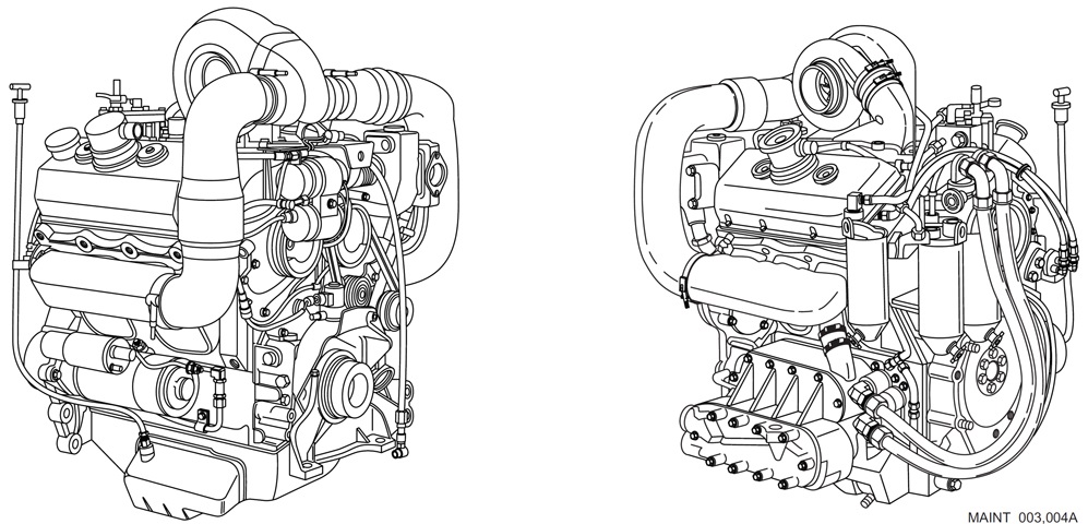
The 6V53T Model 5063-5392 engine featured a TV7303 turbocharger mounted at the air inlet housing; crosshead pistons; 5C55 fuel injectors; a 2-element oil cooler; die cast aluminum rocker covers; an airbox heater; and the blower group had a bypass valve in the rear endplate. Bore and stroke were 3.875" (9.843cm) and 4.5" (11cm), respectively, for a displacement of 318in³ (5.21L). The engine was 39.0" (99cm) long, 36.5" (92.7cm) wide, 41.5" (105cm) tall, and weighed 1,695lb (768.9kg). Compression ratio was 18:1. (Picture from TM 9-2815-205-24.)
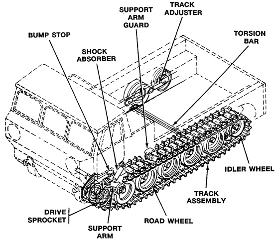
The suspension is sketched in this cross-section. (Picture from TM 9-2350-247-10 C1 Operator's Manual for Carrier, Cargo Tracked, 6-ton M548A1 2350-01-096-9356 (EIC AEU) M548A3 2350-01-369-6081 (EIC AE9).)
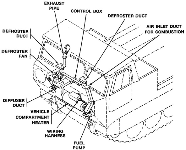
In contrast to earlier vehicles, the cab heater on the M548A3 was an installation rather than a kit, and was located where the winch was formerly mounted. (Picture from TM 9-2350-247-10 C1 Operator's Manual for Carrier, Cargo Tracked, 6-ton M548A1 2350-01-096-9356 (EIC AEU) M548A3 2350-01-369-6081 (EIC AE9).)
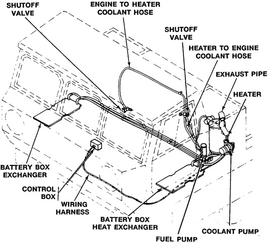
The engine heater kit for the new powerplant can be contrasted to the earlier design. The M548A3 featured batteries under both the driver's and passenger's seats: note the two battery box heat exchangers. (Picture from TM 9-2350-247-10 C1 Operator's Manual for Carrier, Cargo Tracked, 6-ton M548A1 2350-01-096-9356 (EIC AEU) M548A3 2350-01-369-6081 (EIC AE9).)
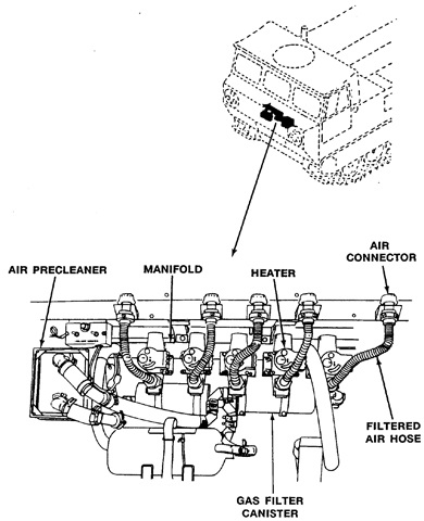
The M548A3 featured a nuclear, biological, and chemical filtration system to which up to four crew could connect their protective masks M42. The NBC filtration system would not protect personnel from carbon monoxide, ammonia, acid, or solvent fumes. Due top chance of frostbite, the crew were not to connected their masks to the filtered air hoses unless the carrier's internal temperature was above 20°F (-7°C). Heaters were provided to warm cold air, but could take 15-20 minutes to reach maximum temperature. The new horizontal position of the portable fire extinguisher is visible at the bottom of the sketch. (Picture from TM 9-2350-247-10 C1 Operator's Manual for Carrier, Cargo Tracked, 6-ton M548A1 2350-01-096-9356 (EIC AEU) M548A3 2350-01-369-6081 (EIC AE9).)
