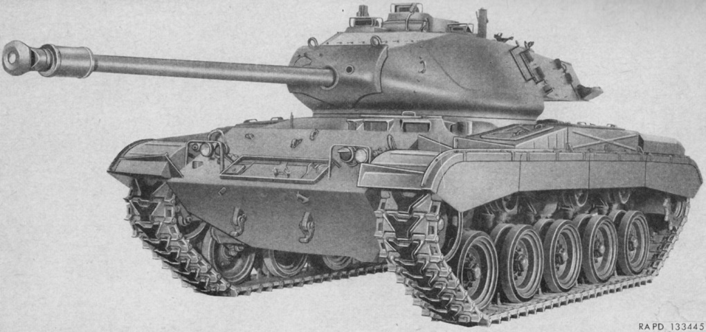
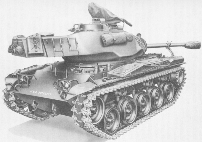
76mm Gun Tank M41 Walker Bulldog.
This early-production machine is equipped with the cast muzzle brake, turret with a high side weld line, squared-off fenders, and sand shields. Note also the early design of the tracks and the wire guards for the gunner's and commander's periscopes on the turret. (Picture from TM 9-730 76-mm Tank Gun T41E1.)
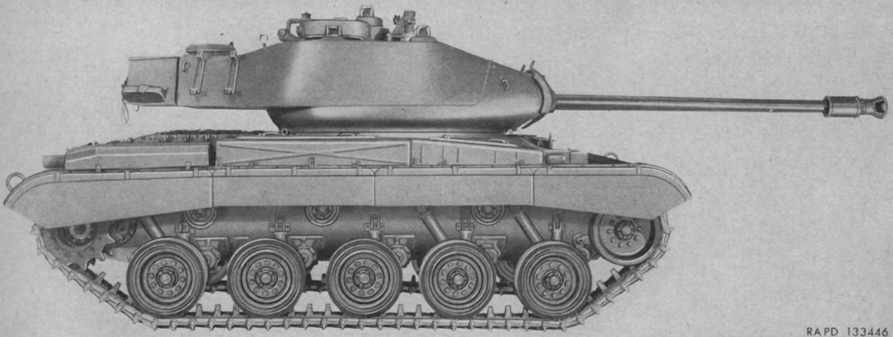
The weld line for the turret is more easily seen in this side view. (Picture from TM 9-730 76-mm Tank Gun T41E1.)
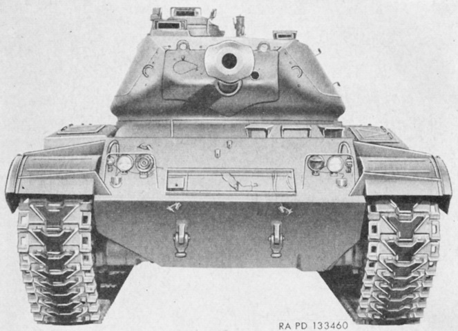
The tank's horn was mounted inboard of the right-side headlight. (Picture from TM 9-730 76-mm Tank Gun T41E1.)
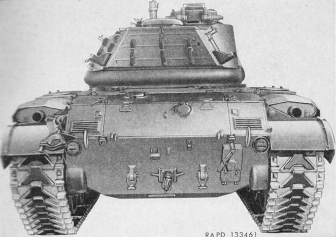
The mufflers for the main engine can be seen on the rear fenders, and the turret bustle stowage box is also obvious from this angle. Lifting rings are just inboard of the taillights. A towing pintle bracket protrudes centrally from the lower rear hull, with a towing lug on each side. The armored case for the external interphone equipment AN/VIA-1 is mounted just inboard of the right-hand lifting ring. This allowed infantry to communicate with the crew of the tank. (Picture from TM 9-730 76-mm Tank Gun T41E1.)
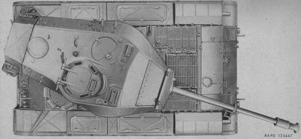
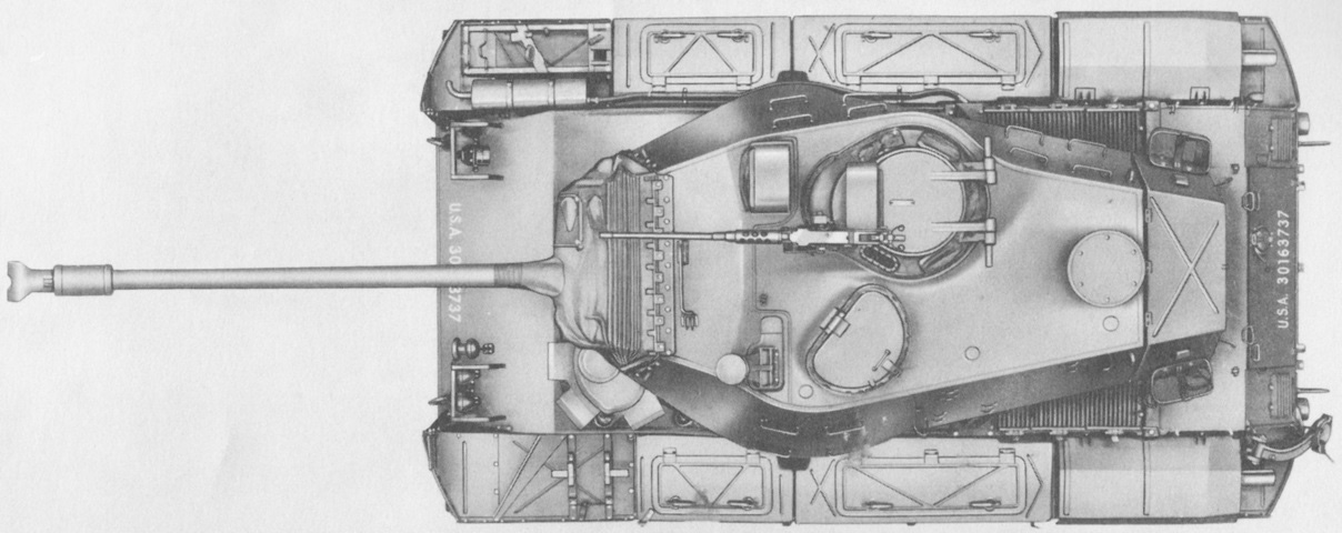
The shape of the turret and its long bustle accentuated by the turret stowage box are highlighted in this top view. The gun is secured in its travel lock, and stowage boxes line both fenders. Note the driver's hatch, which does not have an opening to mount an infrared periscope. The forward .50cal machine gun pintle on the roof is found to the right front of the commander's cupola. (Picture from TM 9-730 76-mm Tank Gun T41E1.)
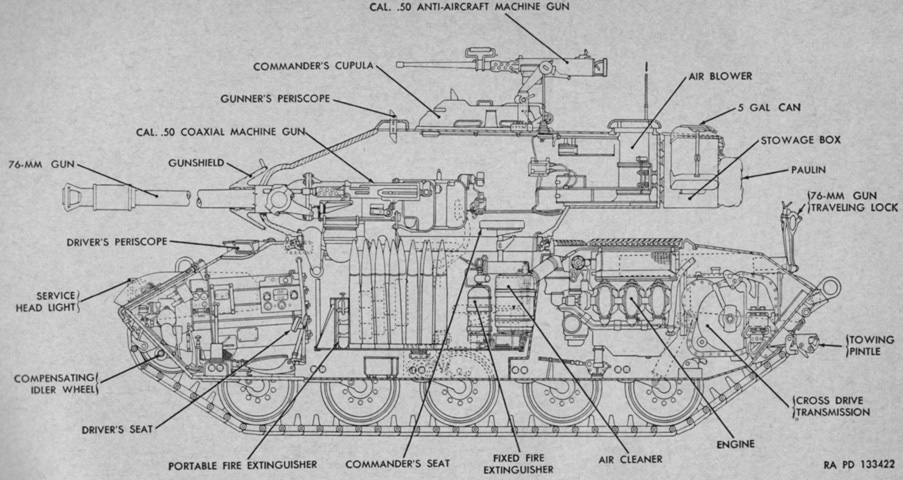
The interior of an early-production tank is sketched here. Note the coaxial .50cal machine gun, which was later replaced with a .30cal machine gun. (Picture from TM 9-730 76-mm Tank Gun T41E1.)
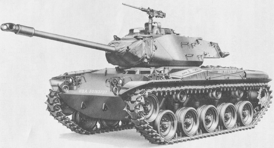
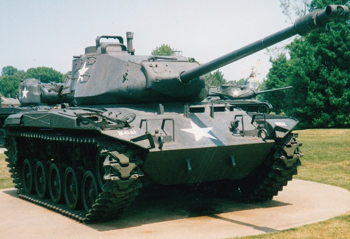
The M41 was a tidy and handsome design. This is a later-production machine, as evidenced by the low turret weld line, angled fenders, fabricated T-shaped muzzle brake, and muffler for the auxiliary generator engine on the right front fender. The track design has also changed, and the pioneer tool rack has been moved to the right fender from the upper front hull. The wire periscope guards on for the gunner's and commander's periscopes have been replaced by strips of armor. (Picture from TM 9-2350-201-12.)
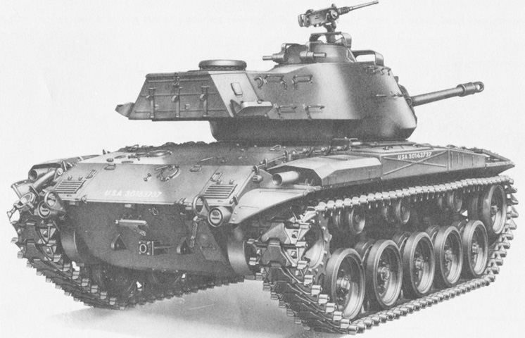
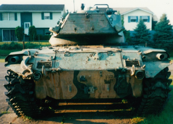
The rear of a late-production tank can be contrasted with the early machine. (Picture from TM 9-2350-201-12.)
The angled fenders can be seen in this top view, and the auxiliary generator engine muffler can be seen inboard of the pioneer tool rack. The driver's hatch on this tank is able to have an infrared periscope installed in the circular opening. The .50cal machine gun pintle has been moved to the left of the commander's cupola. (Picture from TM 9-2350-201-12.)
This stowed tank has its turret reversed and its main gun secured in its travel lock. (Picture from TM 9-2350-201-12.)
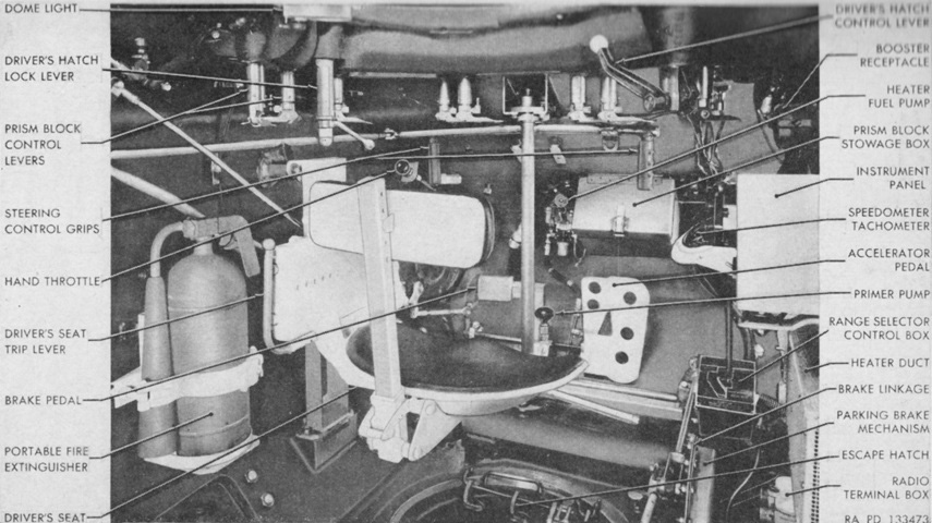
The driver's station of an early-production tank is the subject of this picture. (Picture from TM 9-730 76-mm Tank Gun T41E1.)
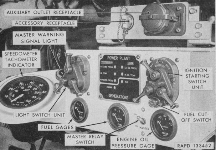
The early driver's instrument panel and accessory outlets are labeled in this image. (Picture from TM 9-730 76-mm Tank Gun T41E1.)
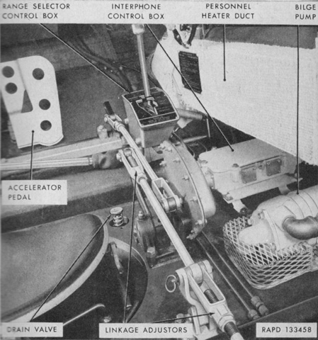
The floor of an early driver's compartment is detailed here. In tanks through serial number 261, two bilge pumps were furnished, one visible here in the driver's compartment and a second in the engine compartment. Each pump had a pumping capacity of 50 gal/min (190L/min). On tanks with serial numbers of 262 and above, the bilge pumps and bilge pump control box were not provided, but mounting pads and bolts were present if they were deemed necessary in-theater. (Picture from TM 9-730 76-mm Tank Gun T41E1.)
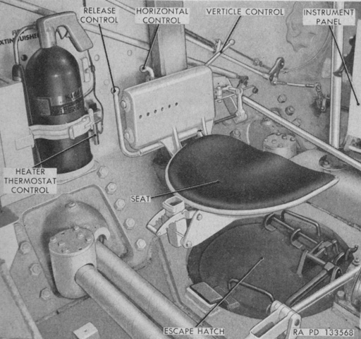
The back rest of the driver's seat has been removed for clarity. A floor escape hatch was present in the driver's compartment; release of the hatch was accomplished by lifting the lever which allowed the hatch to drop free. The release control of the driver's seat dumped the seat so that the escape hatch could be more easily reached. (Picture from TM 9-730 76-mm Tank Gun T41E1.)
An overview of a late driver's position provided in this image; his seatback has again been removed for clarity. (Picture from TM 9-2350-201-12.)
The later-production driver's switch and control boxes are shown here. (Picture from TM 9-2350-201-12.)
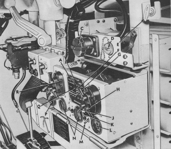
The late driver's instrument panel and accessory outlets are labeled in this image. A. Transmission low-lube-pressure warning light. B. Engine low oil pressure warning light. C. Auxiliary power receptacle. D. Accessory outlet receptacle. E. Auxiliary generator and engine choke handle. F. Engine high oil temperature warning light. G. Engine magneto switch. H. Engine starter switch. J. Magneto booster switch. K. Fuel cut-off switch. L. Engine oil pressure gage. M. Master relay switch. N. Fuel gage. P. Master warning light. Q. Transmission high-temperature warning light. R. Driving light switch assy. (Picture from TM 9-2350-201-12.)
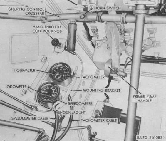
In late-production tanks, the speedometer and tachometer were separated into two gages. The hourmeter readout in the tachometer recorded cumulative engine operating time down to tenths of hours. The time was figured on the basis of a constant 2,053rpm/hour; consequently, the actual engine operating time could differ from that shown on the hourmeter if the engine spent long periods above or below 2,053rpm. (Picture from TM 9-2350-201-12.)
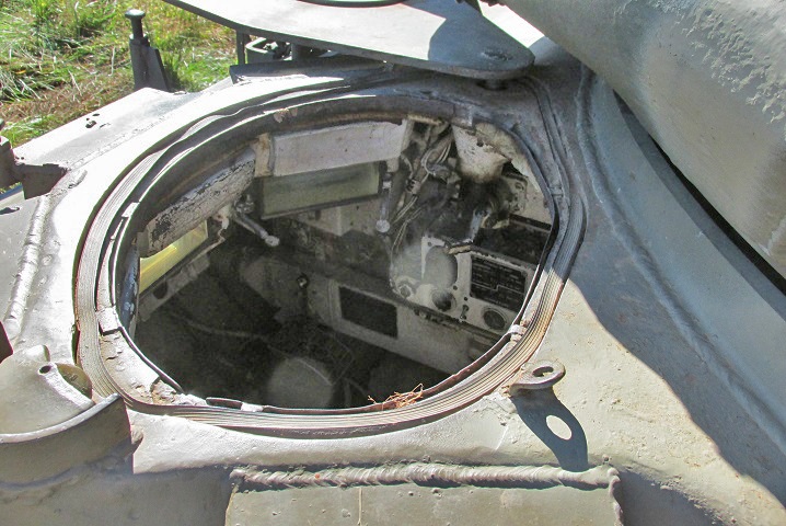
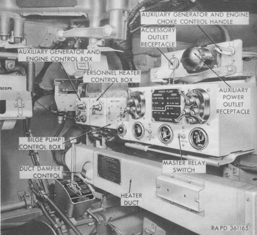
This view is looking down into the open driver's hatch. Light is coming through his periscopes, and to his right, from top to bottom, are the cam-actuated lever for opening and closing his hatch; switchboxes for the personnel heater, bilge pump, and light controls; and the personnel heater duct.
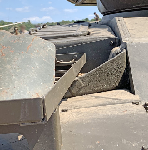
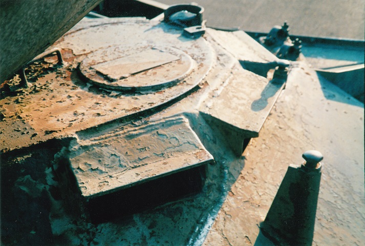
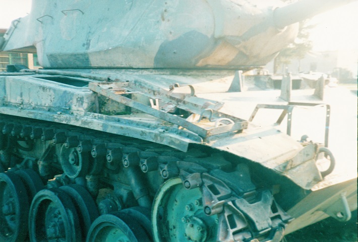
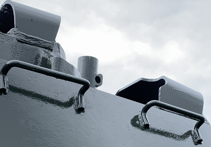
The fender tool rack sat atop the front fender support, as shown here. When the muffler for the auxiliary engine was moved to the front fender as well, the support was modified to allow the muffler to fit.
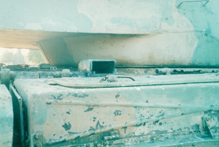
The auxiliary engine muffler crowded the tool rack on the fender. The tool rack was moved outboard, and thanks to the angled front of the fender was also moved backward to rest on the front of the stowage box.
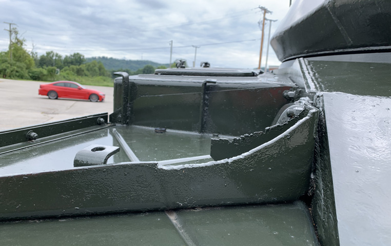
The front fender outrigger was modified to give it a contour that allowed it to act as a support for the muffler.
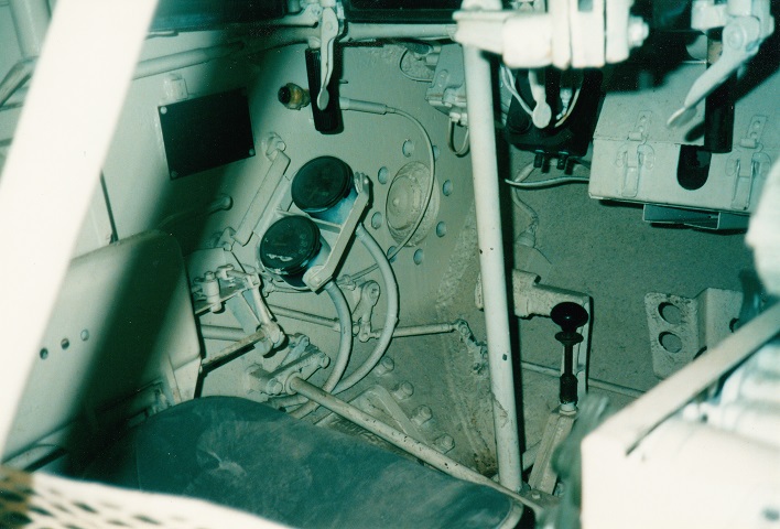
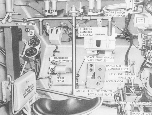
This is the driver's position of the M41 as seen from the turret. The hand throttle is visible just above the left-hand instrument cluster, and the early-style steering crossbar is in the middle of the picture. The handles for the crossbar are black and descend vertically from the ends of the crossbar's horizontal member. The black handle behind the crossbar is the primer pump. The accelerator pedal is just visible to the right of the primer pump handle. The white handles hanging down from the top of the picture are the mounting clamp levers for the driver's M17 periscopes.
The driver's floor escape hatch is seen from the outside. A guard was welded to the hull bottom biased to the driver's right, and the hull front armor protruded downward to the driver's left. Compared to the tank's right side, the hull left side and floor were extended outward to accommodate the driver.
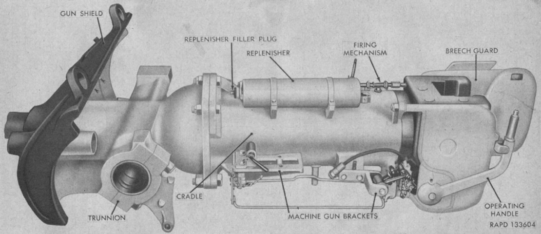
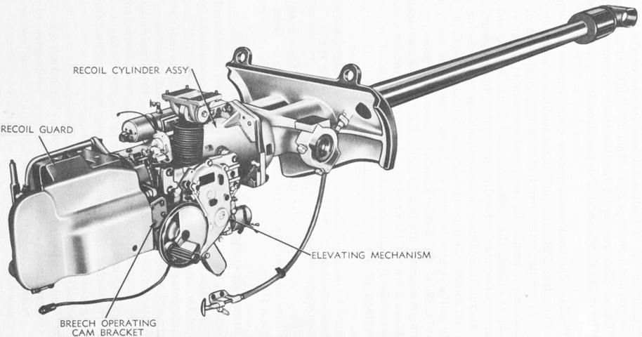
Details of the 76mm gun mount are shown here. A concentric hydrospring recoil mechanism was used in this mount. The recoil cylinder, which was full of hydraulic oil when ready for use, was formed by the inside of the cradle and the outside of the gun tube enclosed by the cradle. The recoil piston was keyed to the gun tube near the cradle's front, and the counterrecoil spring coiled around the gun tube between the recoil piston and the rear of the cradle. The gun mount weighed 1,277lb (579.2kg). (Picture from TM 9-730 76-mm Tank Gun T41E1.)
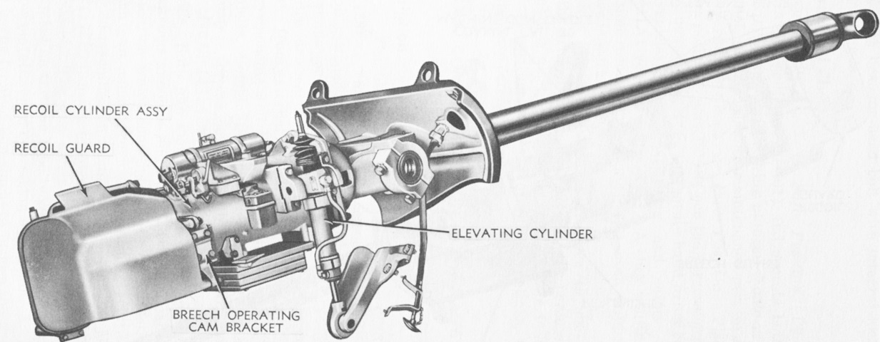
The combination gun mount M76 is seen from the right. The M76 had an attaching surface for the elevating cylinder, and used the telescope mount M92. The complete 76mm gun M32 weighed 1,709lb (775.2kg), and its tube had an estimated accuracy life of 350 equivalent full charge rounds. (Picture from TM 9-2350-201-12.)
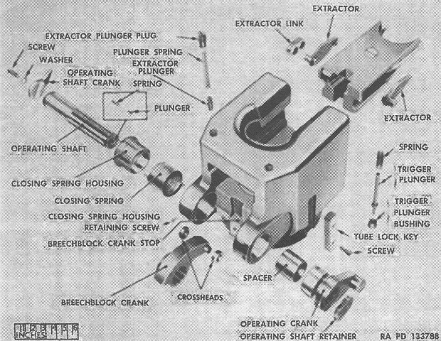
An exploded view of the breech is shown here. After the breechblock was moved the the open position, the breech was semiautomatic where an opening cam and operating crank opened the breech and extracted the expended casing during counterrecoil. (Picture from FM 17-80 Tanks, 76-mm Gun, M41 and M41A1.)
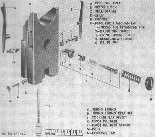
Parts of the breechblock are shown in this image. An inertia-type percussion mechanism found in the breechblock fired the gun. (Picture from FM 17-80 Tanks, 76-mm Gun, M41 and M41A1.)
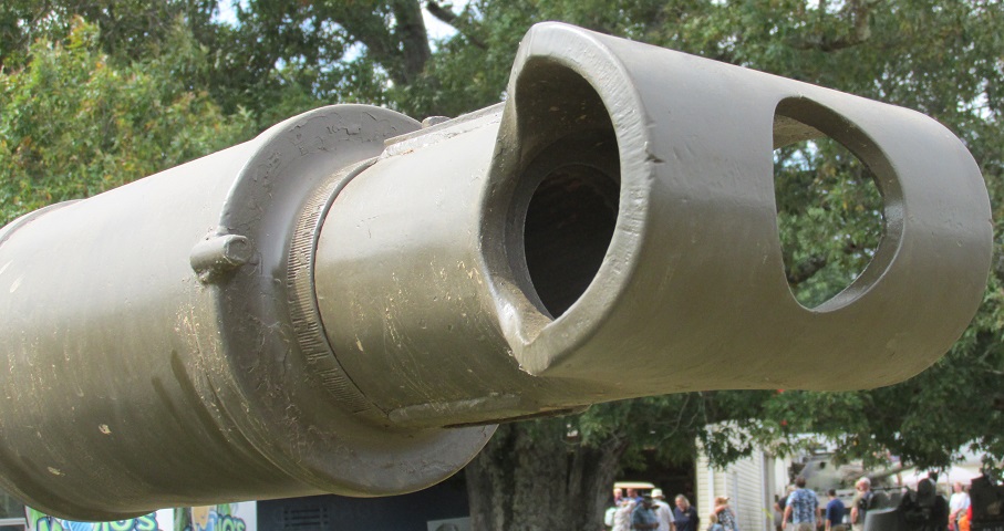
The construction of the fabricated T-shaped muzzle brake is highlighted here. The gun's bore evacuator is directly behind the muzzle brake. The muzzle brake weighed 25lb (11kg).
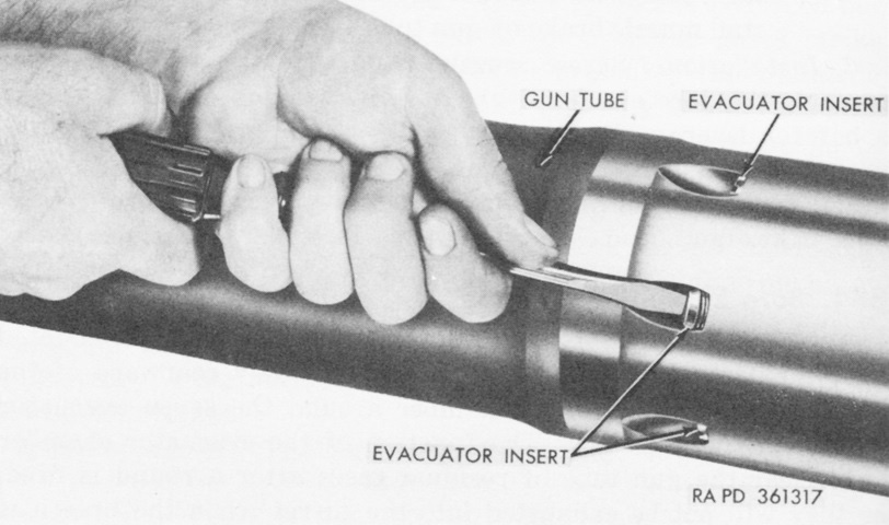
The bore evacuator chamber has been removed, revealing three of the seven bore evacuator inserts. Jets in the inserts allowed some of the propellant gases to flow into the bore evacuator chamber as the fired round passed the jets, increasing the pressure in the chamber. When the round left the gun tube, the pressure reduction in the gun tube allowed the high pressure gases in the bore evacuator chamber to flow out through the inserts and subsequently through the gun's muzzle, recreating the flow of residual gases toward the muzzle before the breech was opened by the gun's counterrecoil action. (Picture from TM 9-2350-201-12.)
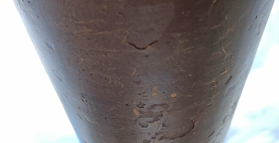
With paint flaking off of the 76mm gun in spots, machining of the gun tube becomes visible.
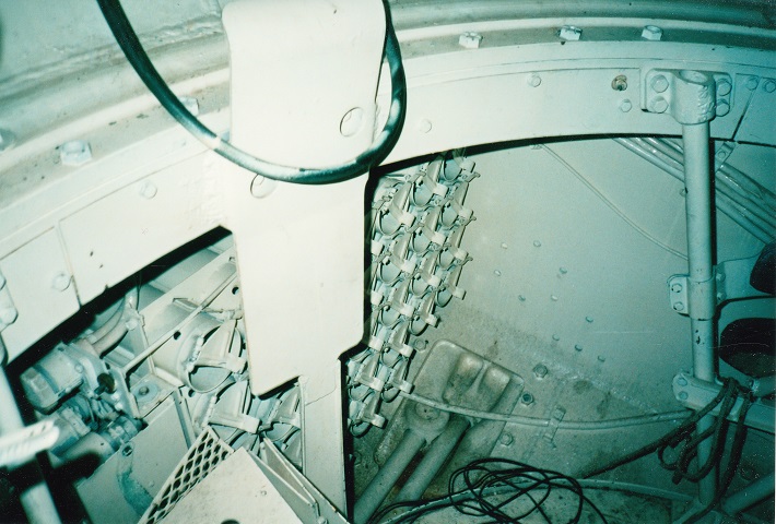
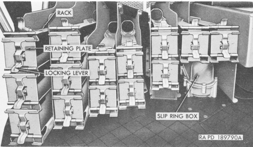
At the right front hull was a 33-round 76mm ammunition rack. The turret is reversed on this tank, with the main gun in travel lock. On the floor of the vehicle, two of the suspending torsion bars are visible. The opposite wheels on the M41, along with most vehicles suspended by torsion bars, are slightly offset, and it is visible why here. The bars run the width of the hull, and force the wheels to be mounted slightly ahead of one another.
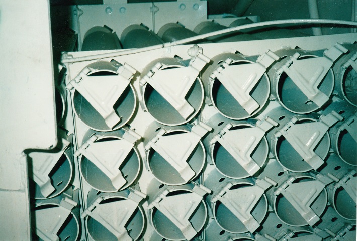
A more detailed view of the hull ammunition rack is presented here. Thirty-three rounds were stowed in the hull, and they were held in place by the retaining plates at the front of each tube.
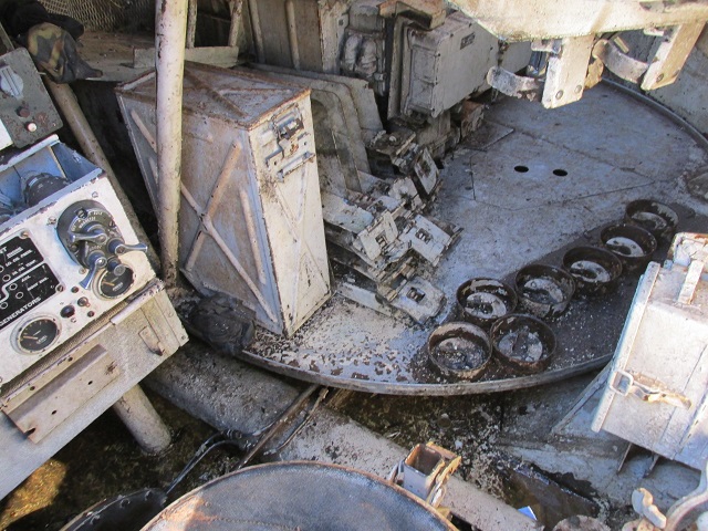
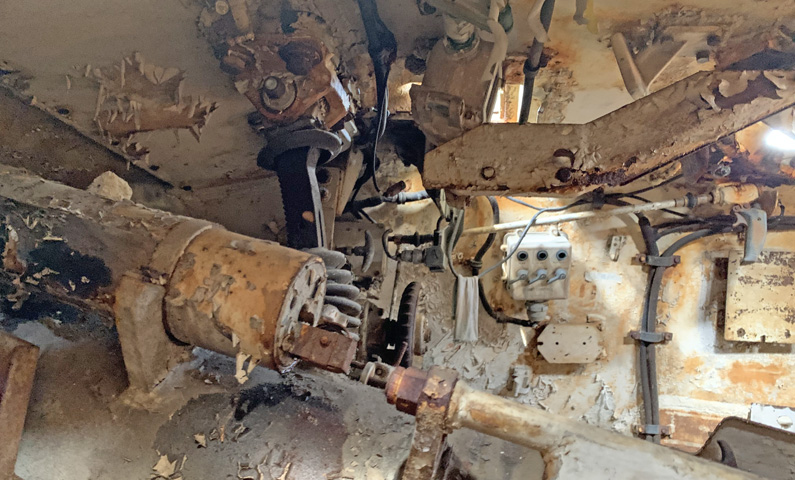
This picture is looking backwards into the tank from the open driver's hatch. The driver's seat--minus its backrest--can be seen at the bottom, and to the left of the image are the driver's control boxes. A torsion bar cover is directly behind the driver's seat, and the turret floor can be seen behind and above the torsion bar cover. We can tell that the tank is an M41/M41A2 by the pulsing relay traversing mechanisms on the turret floor; the Cadillac turret and gun control system found in the M41A1/M41A3 was more compact and there were consequently more horizontal ammunition racks on the turret floor. Some round stands for the ready rack can be seen on the turret floor, but not all are present. The tank would have come with a total of 11, and most of the row of stands near the edge of the floor are missing.
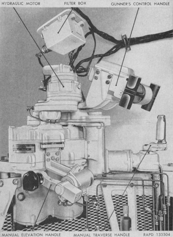
The early pulsing relay gun control system provided powered operation for turret traverse and gun elevation, but it could not meet the added demand of the five-second engagement window. The gunner's control handle was used to hydraulically traverse the turret clockwise or counterclockwise, and hydraulic elevation was achieved by pulling or pushing the top of the handle towards or away from the gunner. (Picture from TM 9-730 76-mm Tank Gun T41E1.)
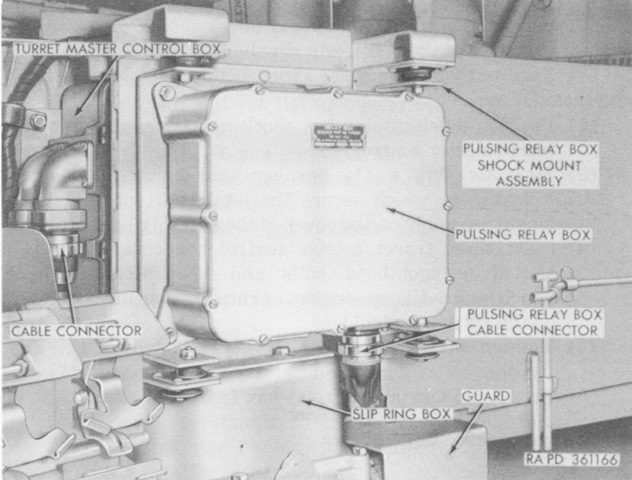
A closer view of the pulsing relay box seen in the previous photo is provided here. The pulsing relay box regulated the speed of the elevating and traversing signal motors in conjunction with the gunner's or commander's control handles. Polarized pulsing relays were generated that closed contacts when the relays flowed in one direction and opened contacts when flowing in the opposite direction. A single set of make-and-break contacts controlled the current flow through the signal motor fields and armatures. Speed regulation was accomplished by varying the amount of time the contacts were closed by increasing the impedance of the closing path the farther the control handle was moved. (Picture from TM 9-2350-201-12.)
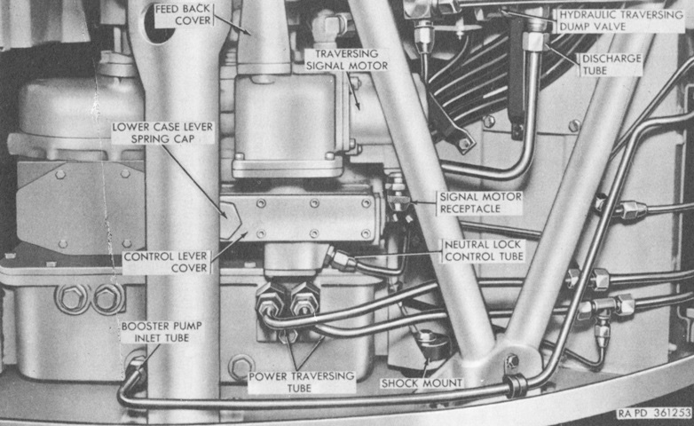
The voluminous hydraulic powerpack of the pulsing relay control system is seen here from the control side. Mounted on the turret basket floor under the tank commander, it consisted of a variable displacement hydraulic pump, a 5hp electric motor, and an oil reservoir. On the upper turret race ring forward of the gunner was the traversing gearbox, which contained the hydraulic motor and gearing that transmitted the traversing power to the turret lower race ring. (Picture from TM 9-2350-201-12.)
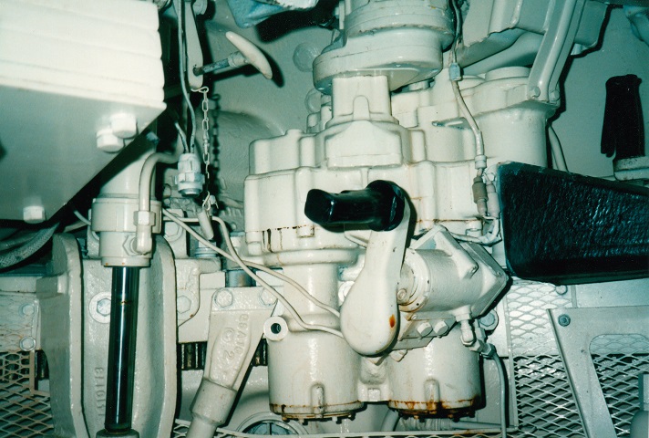
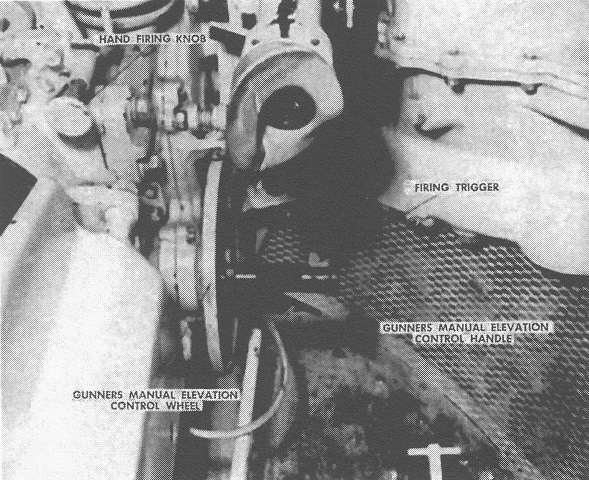
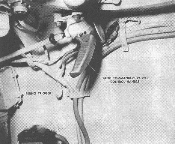
Visible here are some of the gunner's controls of the modified pulsing relay gun control system. The shiny black handle of the elevation hand pump is obvious in the center of the picture, and the traverse hand drive handle is positioned to the upper right of the photo behind the padded arm guard. The telescope cover control handle is painted white and is above and to the front of the elevating pump, but the telescope itself is missing from this vehicle.
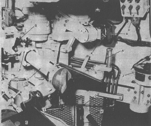
The modifications to the gunner's controls are more easily seen here. The dump valve toggle switch allowed the gunner to traverse the turret manually while the turret motor was on. The pulsing relay system connected the gunner's elevation control handle to the gun via an hydraulic pump and cylinder. Rotating the handle clockwise elevated the gun, and vice-versa. The accumulator handle was connected to a pump that charged the manual elevation system. The legend is as follows: A. Manual traversing control handle. B. Power control handle. C. Manual elevation control handle. D. Turret control box. E. Telescope M97. F. Rear bracket. G. Boresight clamp lever. H. Azimuth boresight knob. I. Elevation boresight knob. J. Azimuth indicator. K. Dump valve toggle switch. L. Firing trigger. M. Firing trigger. N. Accumulator handle. O. Accumulator. P. Manual safety. (Picture from FM 17-80 Tanks, 76-mm Gun, M41 and M41A1.)
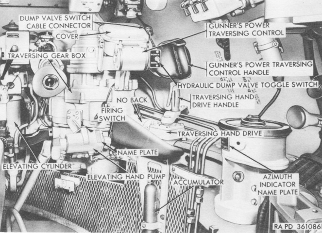
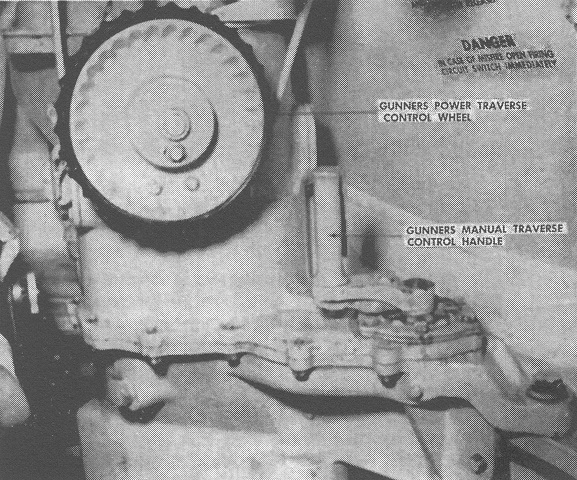
Another view of the gunner's position is provided here. The gunner's and commander's power traversing control handles energized the electrical system that displaced the hydraulic pump slideblock, which then began pumping action in the pump, which flowed oil that operated the hydraulic motor, thereby traversing the turret. Elevation was via manually operated hydraulic power. (Picture from TM 9-2350-201-12.)
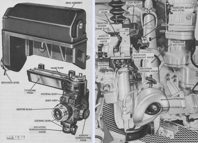
The gunner and commander were both equipped with a periscope M20 or M20A1, shown on the left, and the gunner additionally had a telescope M97, seen on the right. The M20 or M20A1 was composed of a body assembly and a head assembly which allowed a 1x view with a 33°18' horizontal field of view and a 7°9' vertical field of view, and also a 6x sighting system with an 8° field of view. The sprung elevation lever on the head assembly allowed the user to manually elevate the head mirror up to 22° from zero elevation independently, which increased the terrain visible while scanning without elevating the gun. The telescope M97 was an 8x device with a 7°24' field of view. (Picture from TM 9-2350-201-12.)
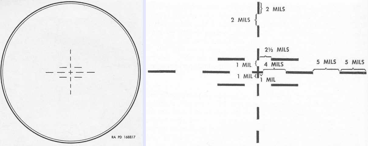
The 6x reticle pattern in the periscope M20 or M20A1 is illustrated on the left and detailed on the right. The reticle was a total of 40 mils wide. The 1x observation window did not have a reticle pattern. (Picture from TM 9-2350-201-12 and FM 17-80 Tanks, 76-mm Gun, M41 and M41A1.)
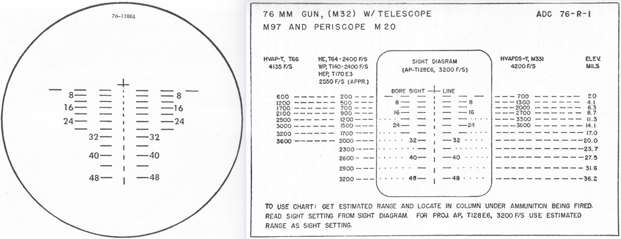
The reticle for the telescope M97 is shown on the left, and an aiming data chart is provided on the right. The reticle was based on the armor-piercing tracer T128E6 (standardized as M339), with the cross in the center representing zero elevation and deflection. Every horizontal line and space represented 5 mils deflection, while each vertical line and space denoted a change of 200 yards (180m), with therefore a total of 400 yards (370m) vertical spacing between the horizontal range lines. The range lines are numbered in hundreds of yards. (Picture from FM 17-80 Tanks, 76-mm Gun, M41 and M41A1.)
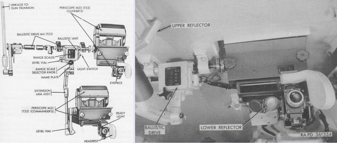
The ballistics drive M4 connected the gunner's and commander's periscope mounts with the 76mm gun, and allowed superelevation to be introduced for the range to the target and ammunition being used. Its ballistics unit contained a range drum with range scales graduated for various types of ammunition, as well as a mil scale for use with ammunition not included on the range scales. The range drum was manually rotated to the estimated range, and the lines of sight of the sighting periscopes and gun were raised or lowered accordingly. The M4 was 32½" (82.6cm) long, 20" (51cm) wide, 25½" (64.8cm) tall, and weighed 41lb (19kg).
The ballistic unit was secured to the turret roof to the left of the gunner's periscope, and the projection system 7597856 seen in the right image used two mirrors to allow the gunner to view the range scale without moving from his periscope. (Picture from TM 9-2350-201-12.)
Partially exploded views of the ballistic drive M4's ballistic unit are diagrammed here. The range scale for the caliber .30 coaxial machine gun ran from 0 to 2,600 yards (2,400m); the high-explosive tracer shell T64 (M352) went from 0 to 4,400 yards (4,020m); and the scales for armor-piercing tracer T128E6 (M339) and HVAP shot from 0 to 5,000 yards (4,600m). All were graduated in hundreds of yards. The mil scale was at the top and read from 0 to 63 mils in half-mil increments. (Picture from TM 9-6065 Ordnance Maintenance Ballistic Drives M3 (T23E1), M4 (T23), T23E2 and T24.)
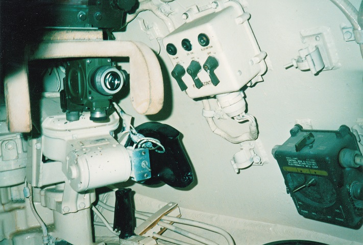
These instruments are above and to the right of those featured in the above picture. The white gun firing control box is mounted to the turret side wall, and to the front of this is the gunner's M20 sighting periscope body minus the unity viewing prism. The gun firing control box had on/off toggle switches for, front to rear, the 76mm gun, the coaxial machine gun, and "automatic," which energized the electric motor in the hydraulic power traversing and elevating powerpack. The handle above the traverse hand drive handle is the gunner's power traverse handle. The switch just to the left of the power traverse handle is the hydraulic dump valve toggle switch.
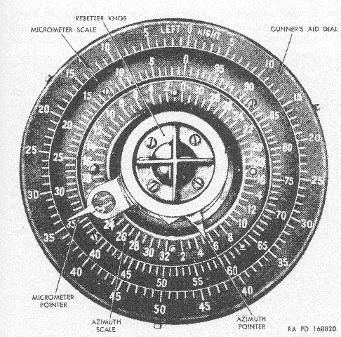
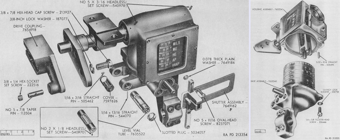
The azimuth indicator M31 is displayed here. Meshed with the turret ring, it assisted the gunner in laying the ordnance for indirect fire. The azimuth scale was graduated in 100-mil intervals and the dial read from 0 to 3,200 mils in each direction. The micrometer scale was graduated counterclockwise in 1-mil increments from 0 to 100. The gunner's aid dial was graduated in 1-mil increments and the dial read from 1 to 50 in each direction. The device was fitted with a directional pointer that was fixed along the longitudinal axis of the hull and showed on the azimuth scale how much the gun had traversed from the hull's longitudinal axis. The azimuth and micrometer pointers could be set to zero with the resetter knob when the sights were set on a desired reference. When the gun was traversed from that reference, the sum of the pointers showed the amount of traverse. The gunner's aid dial could be rotated until its zero matched the micrometer pointer, and then right and left corrections could be made from the gunner's aid dial. (Picture from FM 17-80 Tanks, 76-mm Gun, M41 and M41A1.)
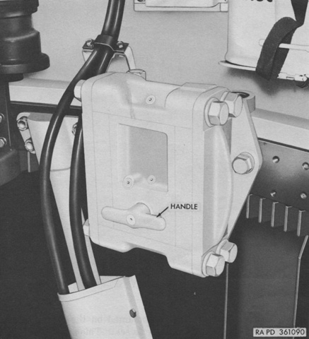
The turret traverse lock was to the gunner's right rear, and was used to hold the turret stationary when traveling with the gun disengaged from its travel lock on the hull rear. The turret was locked by turning the handle counterclockwise and unlocked by slightly pulling the handle outward and rotating it clockwise. (Picture from TM 9-2350-201-12.)
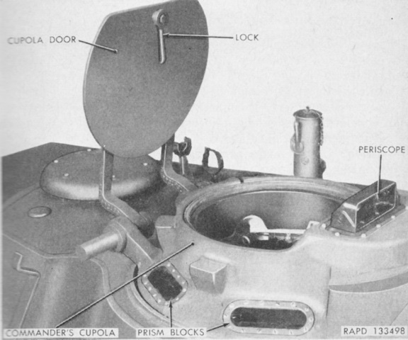
The commander's cupola door is open, allowing a glimpse of its thickness. (Picture from TM 9-730 76-mm Tank Gun T41E1.)
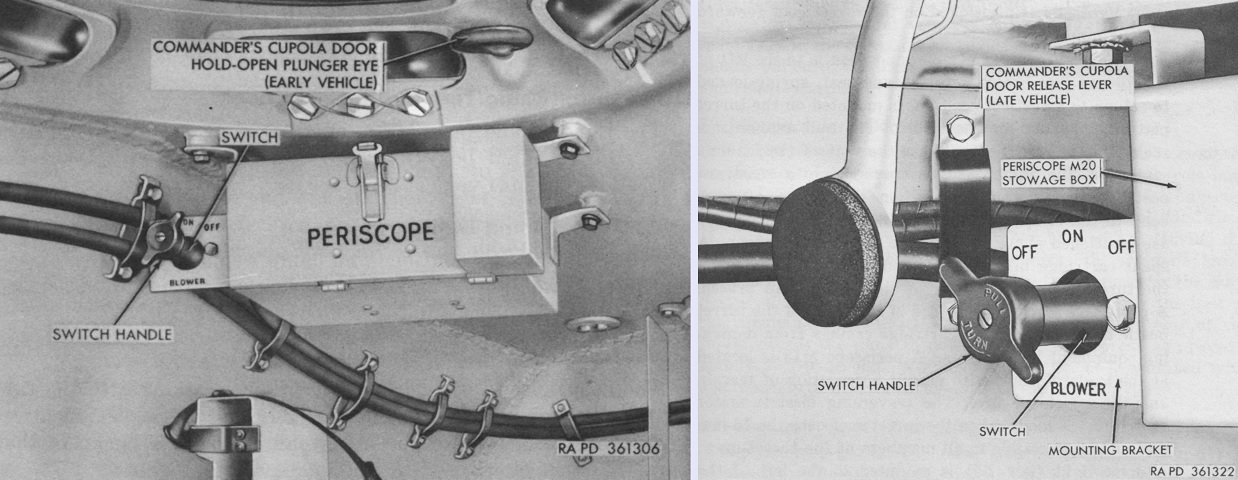
The commander's cupola was held in the open position by a plunger, which could be released by one of two mechanisms. On early tanks, the door was forced downward and the cupola door hold-open plunger eye was pulled back. On later vehicles, a lever was provided that released the plunger when it was pressed to the rear. An early and late cupola are shown on the left and right, respectively. Note that both tanks are equipped with the later-style control for the ventilating blower in the turret bustle, which was a three-position switch with a central ON position and an OFF position to either side. (Picture from TM 9-2350-201-12.)
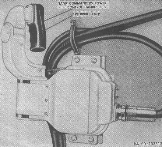
The tank commander was provided with a handle to traverse the turret, and the override lever allowed the commander to take control of the turret and guns from the gunner. The original pulsing relay gun control system provided the commander with the ability to elevate the gun as well as traverse the turret, but in the modified system the commander had no elevation control. (Picture from FM 17-80 Tanks, 76-mm Gun, M41 and M41A1.)
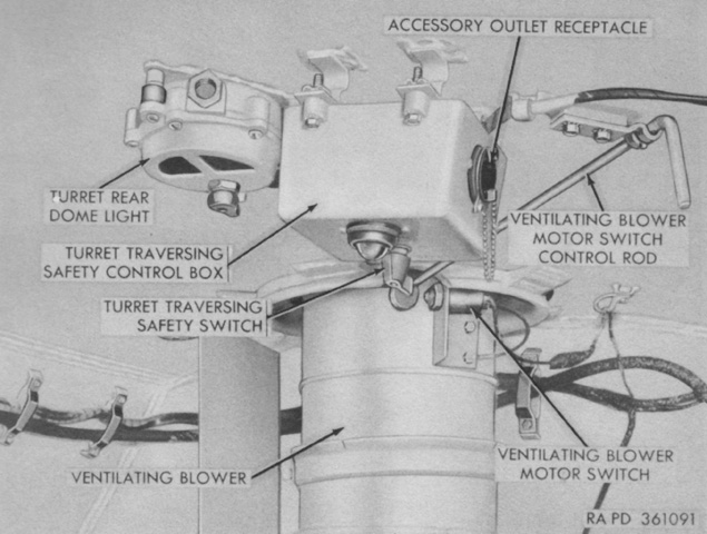
The early control for the turret ventilating blower was a rod that activated the blower when turned a quarter turn clockwise. Turning the blower off involved rotating the rod counterclockwise by the same amount. A 1hp, 5,000rpm motor drove an axial fan to pull 1,000cfm (28.3m3/min) into the turret rear area, which would be discharged through the open breech of the 76mm gun, thereby dispersing propellant fumes. (Picture from TM 9-2350-201-12.)
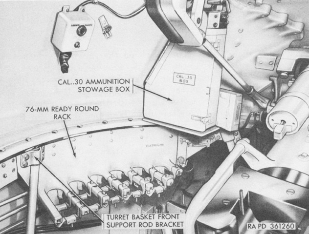
The loader's side of the turret is shown here. The box on the turret wall above the 76mm ready rack is the loader's safety switch. After the main gun had been fired and reloaded, the loader was required to push the button on the lower front of the box for the gun to be fired again. The indicator light above the switch glowed when the gun was ready to fire. This system prevented the gun from firing while the loader was in the way of the recoil. (Picture from TM 9-2350-201-12.)
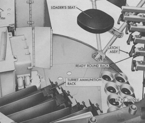
The loader's position is seen from the front. Components of the pulsing relay gun control system can be seen between the turret ammunition rack and the spent cartridge bin. (Picture from TM 9-2350-201-12.)
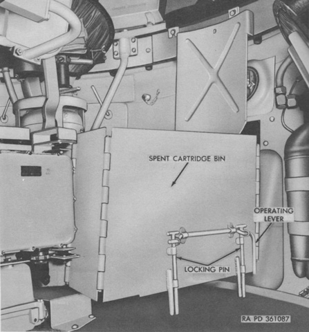
This style of spent cartridge bin was used on M41s and M41s converted to M41A1s. It was hinged to fold against side of the elevated turret floor under the commander's position. To open the bin, the operating lever was moved half a turn upward, then the bin was pulled out to its extended position. Once extended, the operating handle was moved half a turn downward and the locking pins were inserted into holes in the turret floor. To collapse the bin, the operating lever was lifted to remove the locking pins from the turret floor, then the bin was pushed closed and the operating handle returned to its lower locked position.(Picture from TM 9-2350-201-12.)
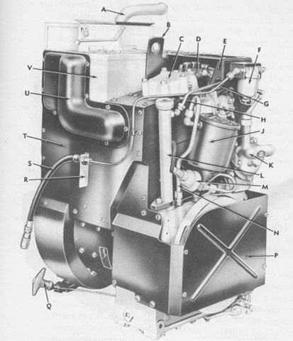
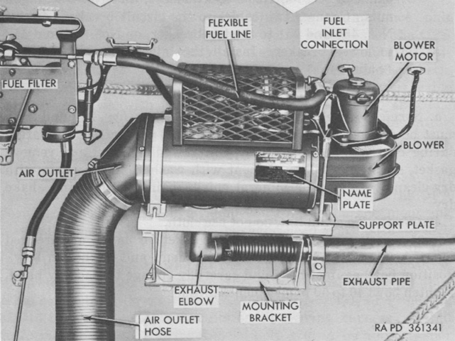
A Detroit Diesel A-41-1 or A-41-2 single-cylinder, air-cooled gasoline engine was connected to a Delco A-8585 300-ampere, 27.5-volt, direct current generator. The generator could be used to start the auxiliary engine, and a cable pull-type starter was also provided. With the generator, the engine weighed 393lb (178kg) dry. The unit was used to recharge the tank's batteries, provide power to electrical systems while the main engine was off, supplement the current generated by the main engine, and heat the engine compartment during cold weather.
A. Exhaust outlet. B. Lifting eye. C. Cylinder head. D. Carburetor. E. Carburetor guard. F. Fuel filter. G. Union-to-fuel filter line. H. Crankcase vent tube. J. Oil filter. K. Governor. L. Oil filter tube. M. Low oil pressure warning light switch. N. Oil filter inlet tube. P. Front panel. Q. Hand starter handle. R. Fuel line mounting bracket. S. Flexible fuel line. T. Right panel. U. Exhaust manifold cover. V. Heat exchanger. (Picture from TM 9-2350-201-12.)
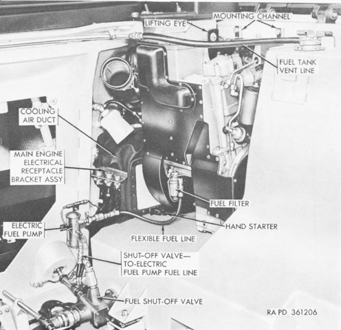
The auxiliary engine is shown here mounted in the front right corner of the engine compartment. As illustrated, starting with vehicle Ordnance serial no.2507, the auxiliary engines were modified by moving the fuel filter and adding an electric fuel pump to reduce the chances of vapor lock during operations in high temperatures. (Picture from TM 9-2350-201-12.)
This photo shows the first location of the smaller auxiliary generator engine muffler, on the right main engine muffler. (Picture from TM 9-2350-201-12.)
The early auxiliary generator engine muffler is present on this machine. (Picture courtesy Joe Wallace.)
This tank has been fitted with the later, larger auxiliary engine muffler usually found mounted on the right front fender. Mounts for the larger muffler have been welded to the main engine muffler cover fore and aft of the mount for the earlier, smaller muffler.
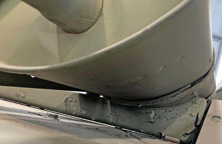
The tubing snaking into the exhaust shroud for the auxiliary engine is shown here.
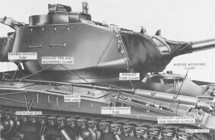
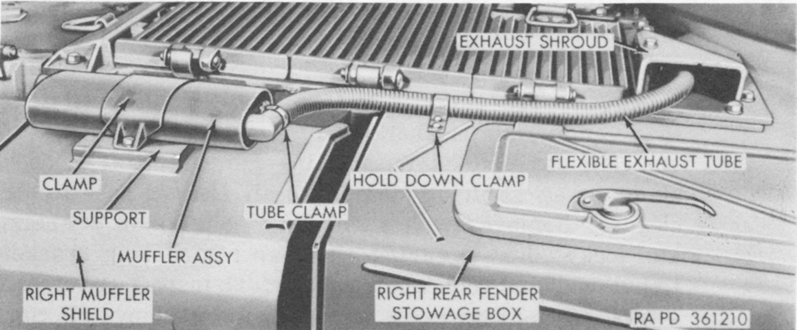
The larger auxiliary generator engine muffler is installed in its final position on the right front fender. (Picture from TM 9-2350-201-12.)
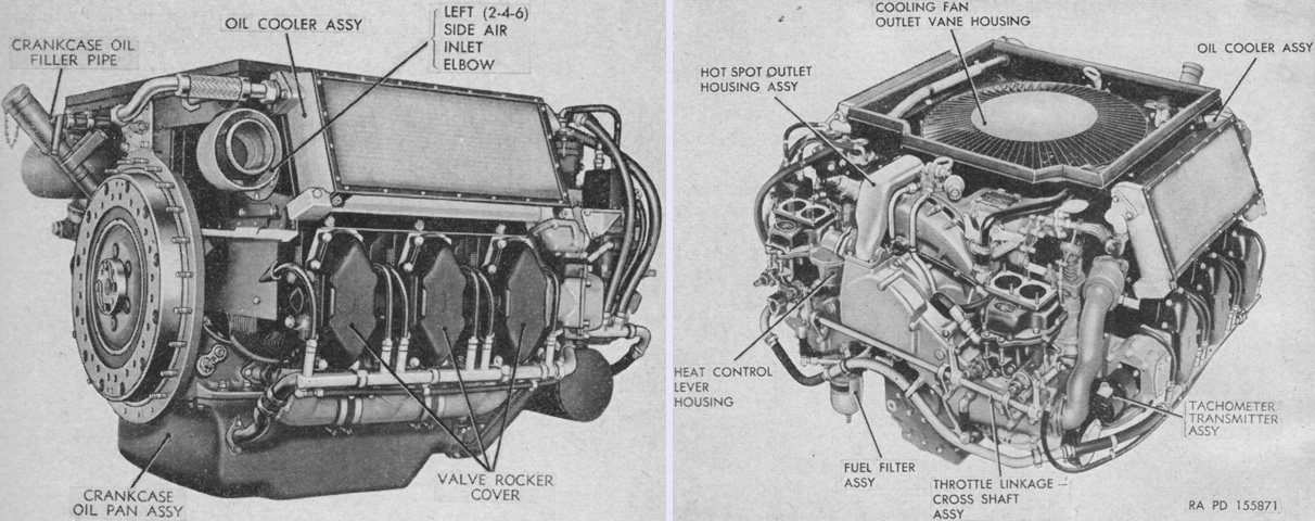
The carbureted AOS-895-3 is shown from the left rear and right front on the left and right, respectively. With the flywheel end of the engine considered the rear, the right and left sides were determined by looking at the engine from the accessory end toward the flywheel end. The cylinders were then numbered 1, 3, and 5 on the right starting at the accessory end, and 2, 4, and 6 on the left. Firing order was 1-6-3-2-5-4. One double-venturi downdraft carburetor was provided for each bank of three cylinders. The engine's oil pan had an 11 gallon (42L) capacity. Including the flywheel assembly, the engine was 47.43" (120.5cm) long, 51.56" (131.0cm) wide, 34.81" (88.42cm) tall, and had a dry weight of 1,894lb (859.1kg) including the flywheel and all accessories. (Picture from TM 9-1730A C2 Continental 6-cylinder Engine Model AOS-895-3.)
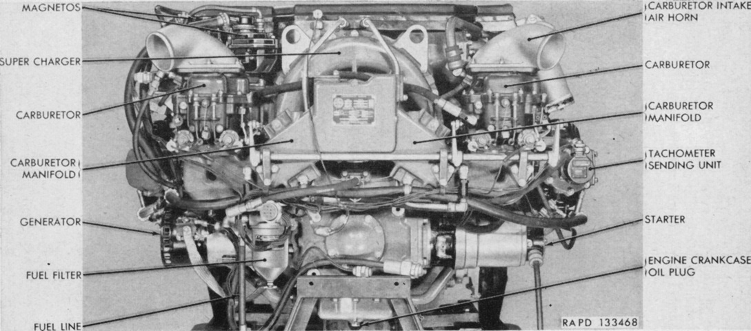
The carburetors were located at the accessory end of the engine. (Picture from TM 9-730 76-mm Tank Gun T41E1.)
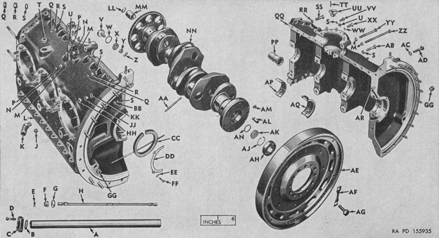
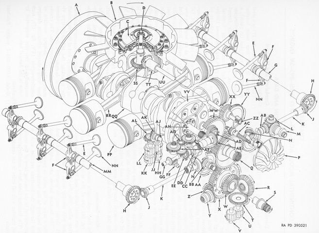
An exploded view of the engine crankcase, crankshaft, and flywheel is provided here. A. Tube, balance, intake manifold. B. Gasket, "O" ring. C. Flange, balance tube. D. Bolt, DLD-hex-HD. E. Pin, cotter. F. Nut, SLTD, cross bolt. G. Spacer, cross bolt. H. Bolt, cross, crankcase. J. Plug, pipe. K. Elbow, hose, crankcase breather line. L. Crankcase, half, right (1-3-5) side. M. Washer, plain. N. Nut, plain. P. Nut, jam. Q. Nut, jam. R. Nut, plain. S. Washer, plain. T. Plug, pipe. U. Plug, pipe. V. Plug, fan tower. W. Gasket, annular. X. Washer, plain, fan tower plug. Y. Nut, SLTD. Z. Pin, cotter. AA. Tube, oil, crankshaft. BB. Nut, SLTD. CC. Seal, oil crankshaft, w/spring, assy. DD. Plate, retaining, oil seal. EE. Washer, plain. FF. Bolt, DLD-HD. GG. Plug, pipe. HH. Nut, jam. JJ. Nut, plain. KK. Washer, plain. LL. Ring, snap. MM. Slinger, oil, crankshaft. NN. Crankshaft and damper hub, assy. PP. Bearing, fan drive horizontal shaft bevel gear. QQ. Crankcase, half, left (2-4-6) side. RR. Washer, plain. SS. Bolt, dowel-type, crankcase alinement. TT. Pin, dowel, fan drive vertical shaft bearing. UU. Bearing, fan drive vertical shaft. VV. Bolt, hex-HD. WW. Washer, plain. XX. Bolt, locking, fan drive horizontal shaft bearing. YY. Bolt, hex-HD. ZZ. Bolt, hex-HD. AB. Bolt, hex-HD. AC. Washer, plain. AD. Bolt, dowel-type, crankcase alinement. AE. Flywheel, w/dowel pin. AF. Lock, flywheel bolt. AG. Bolt, DLD-HD, flywheel to crankshaft. AH. Bearing, ball, transmission shaft pilot. AJ. Ring, snap. AK. Plug, oil, crankshaft (flywheel end). AL. Pin, dowel, AM. Screw, set, hex-socket. AN. Gasket, "O" ring. AP. Bearing, main, crankshaft. AQ. Bearing, main, crankshaft, thrust. AR. Stud. (Picture from TM 9-1730A C2 Continental 6-cylinder Engine Model AOS-895-3.)
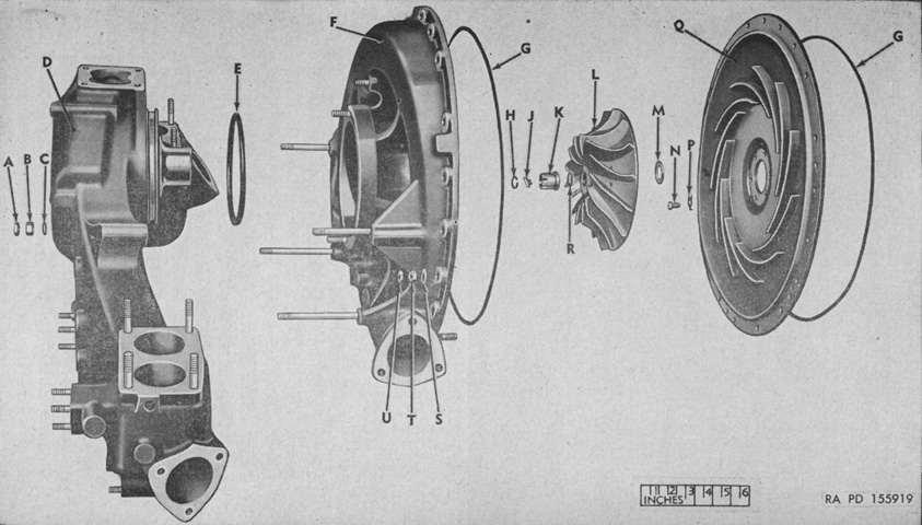
The carburetor elbow and supercharger have been exploded in this image. The supercharger was attached to the accessory case and was driven by the accessory case gear chain. A carburetor was attached to each end of the carburetor elbow, and an outlet in the center of the elbow was attached to the supercharger housing's inlet. The air-fuel mixture was picked up by the supercharger at this inlet, then circulated by the impeller and directed by diffuser vanes via scroll outlets to the intake manifolds on each side of the engine. The supercharger increased the absolute intake manifold pressure to 38-40inHg (1.3-1.4 bar). The intake manifolds between cylinders 5 and 6 were connected by a balance tube to counteract surge, and an aspirator in each manifold used the pressure drop across the carburetors to collect and distribute to the manifolds any raw gasoline that remained in the carburetor elbow. A. Nut, jam. B. Nut, plain. C. Washer, plain. D. Elbow, carburetor. E. Gasket, "O"ring. F. Housing, supercharger. G. Gasket, "O" ring. H. Ring, locking, impeller nut. J. Lock, impeller nut. K. Nut, locking, impeller. L. Impeller, supercharger. M. Shim, impeller. N. Bolt, hex-HD. P. Washer, tab. Q. Diffuser, supercharger. R. Washer, plain. S. Washer, plain. T. Nut, plain. U. Nut, jam. (Picture from TM 9-1730A C2 Continental 6-cylinder Engine Model AOS-895-3.)
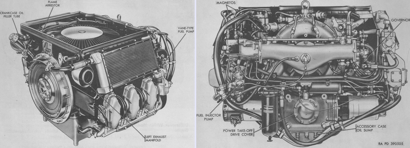
The AOSI-895-5 dispensed with the carburetors in favor of a fuel injection system, and is seen from the left rear and from the front on the left and right above, respectively. Mounted on the left side of the accessory case, the fuel injector pump sensed the engine speed, intake manifold air pressure, and intake air temperature and delivered a correctly-metered dose of fuel based on those varying factors. Including the flywheel, the engine was 39.19" (99.54cm) tall, 41.38" (105.1cm) long, and 51.52" (130.9cm) wide, and weighed 1,865lb (846.0kg) dry with all accessories. Gross torque was increased to 1,010 lb-ft at 2,400rpm. (Picture from TM 9-2805-212-35.)
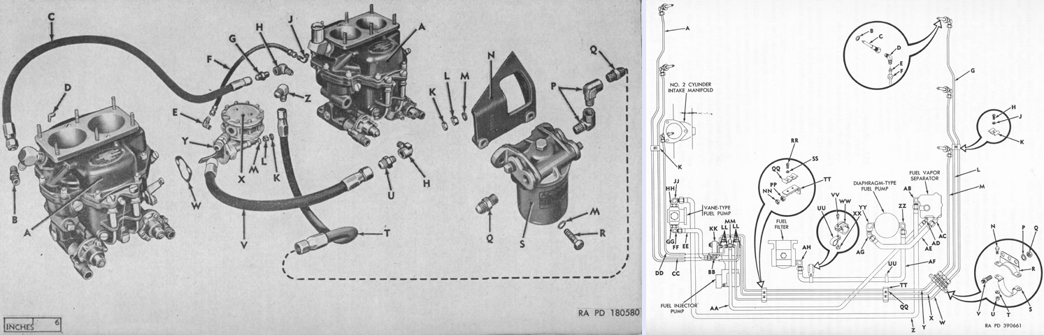
The fuel system of the AOS-895-3 on the left can be contrasted with the schematic of the AOS-895-5's fuel system on the right. The legend for the left image is: A. Carburetor, assy. B. Elbow, tube, 45°. C. Line, flexible, carburetor-to-carburetor. D. Elbow, street, 90°, carburetor-to-magneto-line. E. Elbow, flared tube, 90°. F. Line, flexible, vent, fuel-pump-to-carburetor. G. Connector, tube. H. Elbow, pipe, 90°. J. Elbow, flared tube, 90°. K. Nut, jam. L. Nut, plain. M. Washer, plain. N. Bracket, fuel filter. P. Elbow, pipe, 90°. Q. Connector, tube. R. Bolt, DLD-hex-HD. S. Filter, fuel, assy. T. Line, flexible, fuel-filter-to-fuel-pump. U. Connector, tube. V. Line, flexible, fuel-pump-to-carburetor. W. Gasket, fuel pump. X. Pump, fuel, assy. Y. Elbow, flare tube, 15°. Z. Elbow, flared tube, 90°.
The legend for the right image is: A. Tube assembly. B. 0.5150 id, 0.6900 od, 0.0600 thick plain copper washer. C. Fuel injector nozzle assembly. D. ⅛" (.318cm) 90° elbow. E. ¼" (.64cm) safety sleeve. F. ¼" (.64cm) safety sleeve nut. G. Tube assembly. H. No. 10 x ½ fillister-head screw. J. 13/64 id, 7/16 od, 0.0320 thick flat washer. K. Clamp. L. Tube assembly. M. Tube assembly. N. 5/16 x 23/32 hex-head bolt. P. ½" (1.3cm) internal-teeth lock washer. Q. ½" (1.3cm) hex nut. R. Outer support bracket. S. Inner support bracket. T. 5/16" (.7938cm) lock washer. U. 5/16" (.7938cm) hex nut. V. ¼" (.64cm) tube union. W. Tube assembly. X. Tube assembly. Y. Tube assembly. Z. Hose assembly. AA. Hose assembly. BB. ¼" (.64cm) 90° elbow. CC. Tube assembly. DD. Tube assembly. EE. Hose assembly. FF. ¼" (.64cm) 90° elbow. GG. Bushing. HH. Bushing. JJ. ⅜" (.953cm) 90° adapter elbow. KK. Fuel cutoff solenoid valve assembly. LL. ⅛" (.318cm) connector. MM. ⅛" (.318cm) 90° adapter elbow. NN. ⅜" (953cm) hex stamped nut (model AOSI-895-5M engine only). PP. ⅜" (.953cm) hex nut (model AOSI-895-5M engine only); ⅜" (.953cm) hex self-locking nut (model AOSI-895-5 engine only). QQ. Clamp. RR. No. 10 x ½ fillister-head screw. SS. 13/64 id, 7/16 od, 0.0320 thick flat washer. TT. Bracket. UU. Clamp. VV. No. 10 x ½ fillister-head screw. WW. Clamp. XX. No. 10 hex self-locking nut. YY. ⅜" (.953cm) 90° elbow. ZZ. ⅜" (.953cm) 90° adapter elbow. AB. ⅜" (.953cm) 90° adapter elbow. AC. ⅜" (.953cm) 45° elbow. AD. ⅛" (.318cm) 45° elbow. AE. Hose assembly. AF. Hose assembly. AG. ⅜" (.953cm) 45° elbow. AH. ⅜" (.953cm) 90° adapter elbow. (Picture from TM 9-1730A C2 Continental 6-cylinder Engine Model AOS-895-3 and TM 9-2805-212-35.)
The gear train and major operating parts of the AOSI-895-5 are sketched in this diagram. A. Flywheel assembly. B. Cooling fan rotor. C. Fan drive clutch assembly. D. Fan drive vertical drive shaft. E. Exhaust valve. F. Valve rocker assembly. G. Right camshaft assembly. H. Camshaft driven gear. J. Camshaft drive gear. K. Camshaft drive shaft. L. Governor driven gear. M. Fuel pump driven shaft gear. N. Camshaft drive idler driven gear assembly. P. Supercharger impeller. Q. Accessory drive gear. R. Starter drive bevel gear. S. Power take-off drive shaft assembly. T. Oil pump drive gear. U. Accessory case scavenger oil pump drive impeller. V. Accessory case scavenger oil pump driven impeller. W. Starter driven gear. X. Power take-off drive gear. Y. Generator driven shaft gear assembly. Z. Generator drive gear assembly. AA. Camshaft drive idler gear. BB. Camshaft drive idler bevel gear. CC. Spark advance governor unit assembly. DD. Spark advance governor coupling assembly. EE. Magneto driven idler gear. FF. Fuel injector pump driven shaft gear. GG. Fuel injector pump drive shaft gear. HH. Pressure oil pump driven impeller. JJ. Scavenger oil pump driven impeller. KK. Pressure oil pump drive impeller. LL. Scavenger oil pump drive impeller. MM. Left camshaft assembly. NN. Intake valve. PP. Piston. QQ. Crankshaft assembly. RR. Connecting rod assembly. SS. Fan drive vertical drive shaft driven gear. TT. Fan drive vertical drive shaft drive gear. UU. Fan drive horizontal drive shaft. VV. Vibration damper counterweight. WW. Accessory drive idler gear. XX. Fan drive shaft gear. YY. Impeller drive shaft gear. ZZ. Impeller drive shaft. AB. Fuel pump and governor drive gear. AC. Impeller driven shaft gear. AD. Magneto drive gear assembly. AE. Magneto driven shaft gear assembly. AF. Magneto driven gear. AG. Magneto driven idler shaft gear. AH. Accessory drive shaft. AJ. Oil pump drive shaft. AK. Pressure pump drive gear. AL. Pressure pump driven gear. (Picture from TM 9-2805-212-35.)
Modification Work Order 9-2805-212-40/1 provided instruction on modifying carbureted AOS-895-3 engines to use fuel injection, and these engines were designated AOSI-895-5M. The AOSI-895-5M retained a few differences from factory-produced AOSI-895-5s. Hotspot devices were unnecessary with fuel injection, so while the AOS-895-3's exhaust manifold hotspot outlet extensions were eliminated from the AOSI-895-5, they were sealed with a cover on the AOSI-895-5M. These outlet extensions emerged through openings in the engine shroud's accessory end; similarly, these openings were deleted from AOSI-895-5 and sealed on AOSI-895-5M. The AOSI-895-5M's flywheel incorporated a torsion damper assembly which was omitted on the AOSI-895-5. Finally, all hex stamped nut and plain hex nut applications on the AOSI-895-5M were replaced by hex self-locking nuts on the AOSI-895-5 except the twelve .4375" (1.111cm) holddown nuts securing each cylinder to the crankcase. (Picture from TM 9-2805-212-35.)
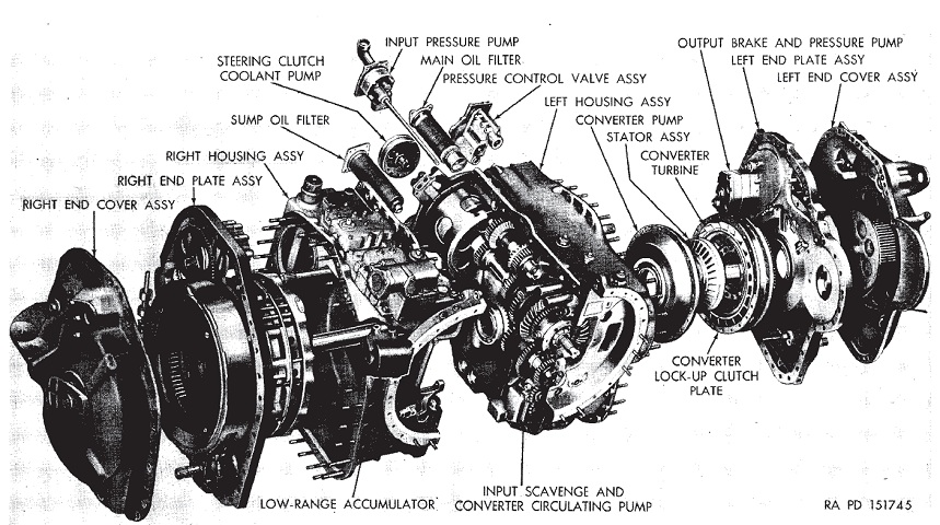
An exploded view of the tank's transmission is shown here. It weighed ~2,000lb (~900kg), was 31.09" (78.94cm) long, 33.50" (85.09cm) tall, and 44.75" (113.7cm) wide. Its oil system had a 14 gallon (53L) capacity. (Picture from TM 9-1730B Cross-Drive Transmission Models CD-500-3 and -4 (Allison and GM).)
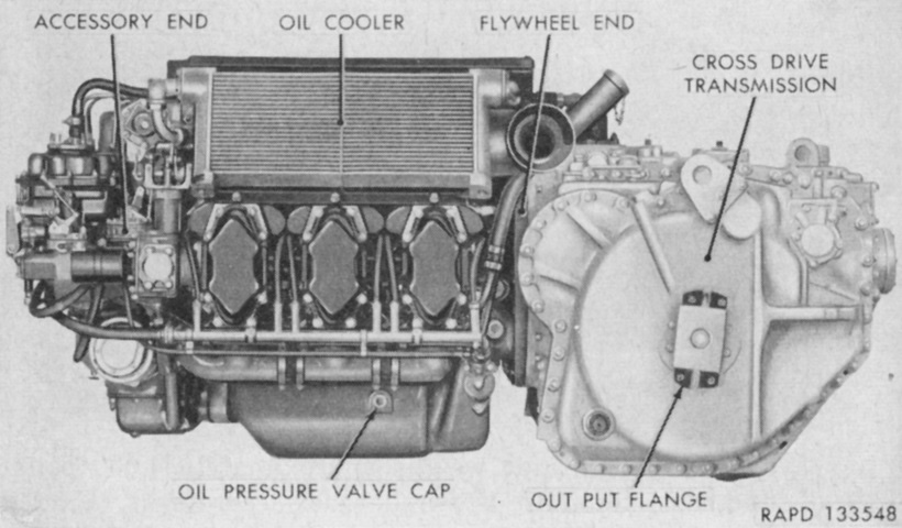
Able to be removed as a unit, the powerpack weighed ~4,000lb (~1,800kg). The accessory end of the engine was considered the front, while the right or left side was determined by looking at the engine from the accessory end. The right side of the engine is therefore shown in this picture. The right-side cylinders were numbered from the accessory end as 1, 3, and 5; on the opposite side are cylinders 2, 4 and 6, with 2 closest to the accessory end. Firing order was 1-6-3-2-5-4. (Picture from TM 9-730 76-mm Tank Gun T41E1.)
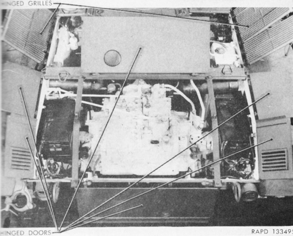
The engine and transmission access doors and grilles are open, showing the transmission flanked by batteries on each side. (Picture from TM 9-730 76-mm Tank Gun T41E1.)
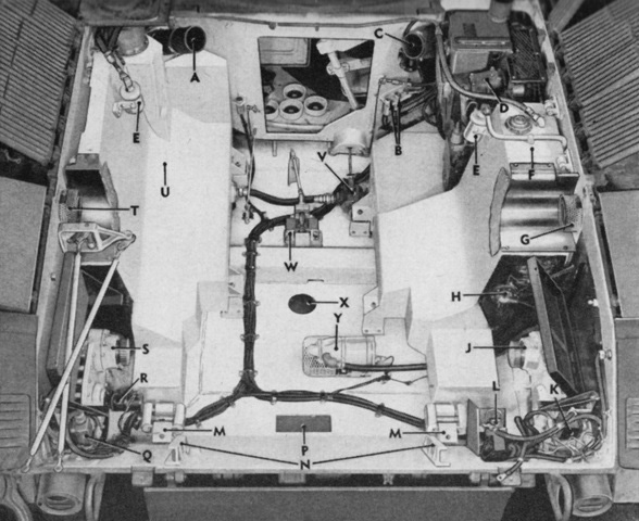
The empty powerplant compartment is detailed here. Note the 76mm ammunition turret floor stowage visible through the open bulkhead. The filler for the right fuel tank was located under the engine compartment top grille doors, and was for emergency use only. Typically, the right fuel tank was filled via a connection with the left fuel tank, the filler for which was just to the turret's left rear. A. Left air-cleaner air duct. B. Generator connector. C. Right air-cleaner air duct. D. Auxiliary generator and engine. E. Fire extinguisher nozzle. F. Right fuel tank. G. Right exhaust stack. H. Fuel gage sending unit. J. Right final drive. K. Master relay. L. Communications box. M. Power plant rear mount. N. Guide rail. P. Transmission oil drain cover. Q. Starter relay. R. Speedometer sending unit. S. Left final drive. T. Left exhaust stack. U. Left fuel tank. V. Fuel shut-off valve. W. Power plant front mount. X. Engine oil drain cover. Y. Bilge pump. (Picture from TM 9-730 76-mm Tank Gun T41E1.)
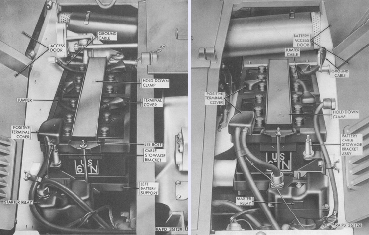
A pair of 12-volt, 23-plate, 100 ampere-hour batteries were mounted on each side of the engine compartment. The two batteries in each set were connected in series, and the two sets were connected in parallel to make a 24-volt electrical system. The left-side batteries and the starter relay are seen on the left, with the right-side batteries and master relay on the right. (Picture from TM 9-2350-201-12.)
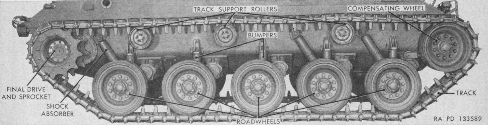
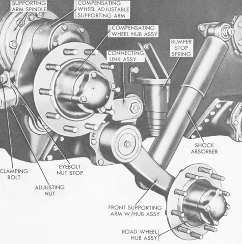
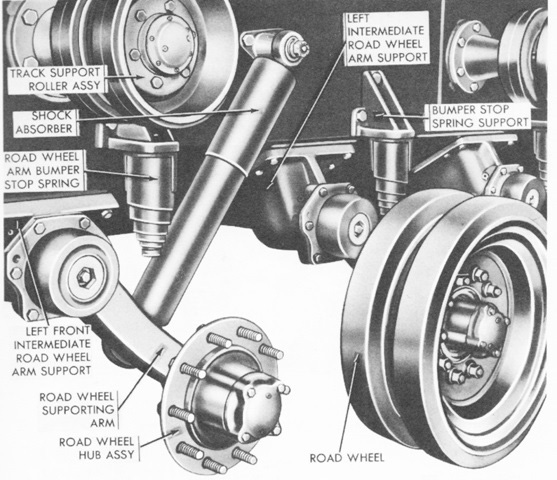
Nomenclature for the suspension is given in this picture. (Picture from TM 9-730 76-mm Tank Gun T41E1.)
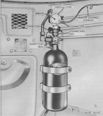
Two fixed 10lb (4.5kg) CO2 fire extinguishers were mounted on the fighting compartment side of the engine compartment bulkhead. Tubing routed the contents of these extinguishers into the engine compartment to suffocate fires there. In addition, a 5lb (2.3kg) portable extinguisher was kept in a bracket behind the driver on the hull left. Early tanks were fitted with vertical remote control units that worked with Kidde cylinders, as seen on this left-side extinguisher bottle. (Picture from TM 9-2350-201-12.)
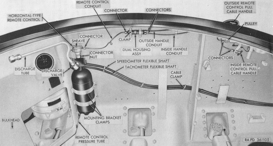
The fixed extinguishers of late tanks were fitted with horizontal remote-control heads, which could be used with any type of cylinder. The handles for activation of the extinguishers can be seen at the right: one inside the hull behind the driver's seat and one outside the hull behind the driver's hatch. Note the cylindrical engine air cleaner visible behind the bulkhead at the left. (Picture from TM 9-2350-201-12.)
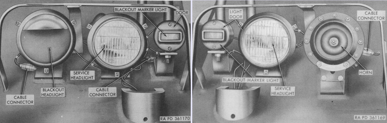
The left and right headlights found on tanks with Ordnance serial numbers through 260 are shown in the left and right images, respectively. The blackout headlight contained a shielded lamp which provided a limited amount of illumination for dimout operations, and was found outboard of the left service headlight. (Picture from TM 9-2350-201-12.)
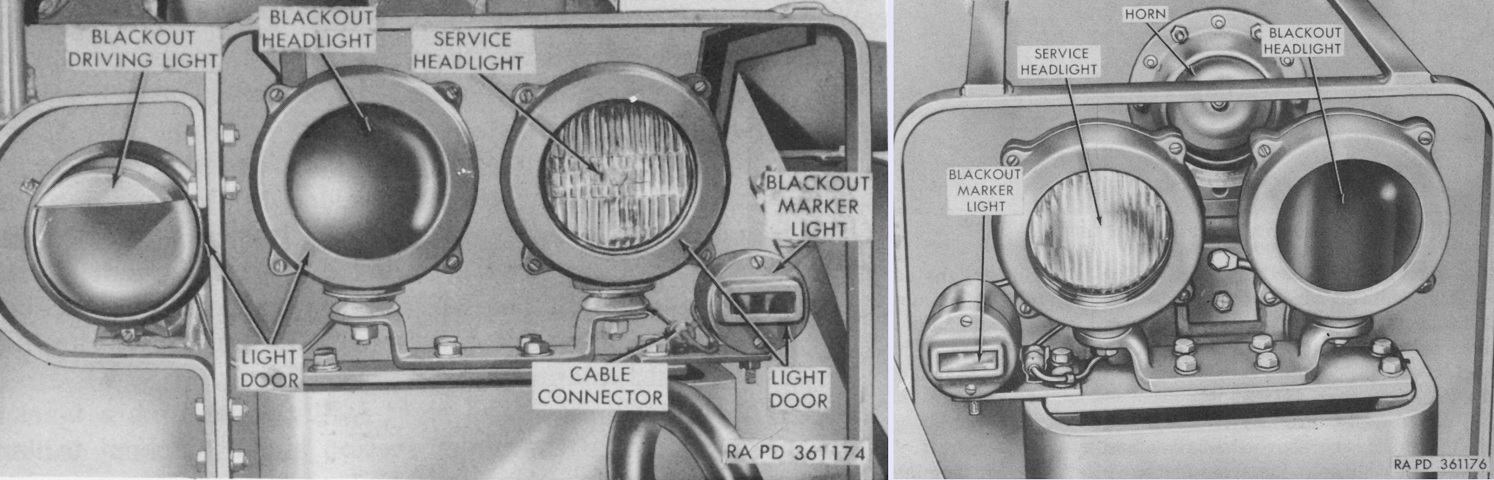
The left and right headlights found on tanks with Ordnance serial numbers 261 and above are shown in the left and right images, respectively. In contrast to the blackout driving light, which was the same as the blackout headlight found on earlier tanks, the blackout headlights found on late tanks were used for total blackout operations in combination with the driver's infrared periscope M19. (Picture from TM 9-2350-201-12.)
A 20,000 btu/hour gasoline-burning personnel heater was found at the front right of the driver's compartment. The heater had its own fuel pump and filter, and once activated would produce warm air within 3 minutes. A differential of 70°F (20°C) existed between the high and low settings on the thermostat; on low the heat output was 10,000btu and fuel consumption was ⅛gal (.473L) per hour. On early tanks, a safety reset lever was provided if the heater did not produce warm air within three minutes. The lever was held in the RESET position for 30 seconds, then the heater was tried up to twice more. On later vehicles, the safety reset lever was replaced by holding the heater control switch in the PRIME position for 30 seconds for up to two more tries at starting the heater. (Picture from TM 9-2350-201-12.)
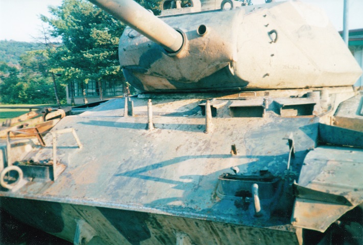
This is a later-production M41A1, as evidenced by the turret's low side weld line, angled fenders, T-shaped muzzle brake, and the placement of the auxiliary generator engine muffler on the front right fender. Just outboard of the small muffler is the pioneer tool stowage rack. The gunner's and commander's periscope guards are visible on the right side of the turret, and the mount for the .50cal MG is beside the commander's cupola. The locking pins for the driver's hatch are positioned on the tank's glacis to the right of his door.
The combination gun mount M76A1 mounted an elevating mechanism on the right side, and the telescope mount M92A1 was attached to the elevating mechanism rather than the gun cradle, as on the gun mount M76. It weighed 1,397lb (633.7kg). (Picture from TM 9-2350-201-12.)
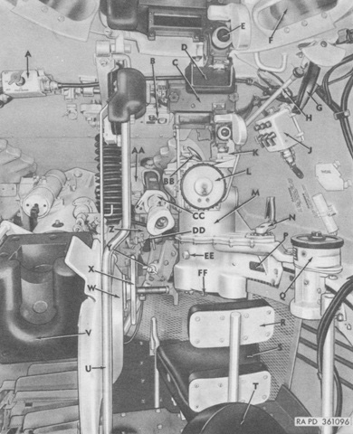
An overview of the gunner's position as viewed from the commander's position is provided in this picture. The compactness of the traversing mechanism compared to the pulsing relay system is apparent. A. Traversing electric motor switch. B. Dome light. C. Periscope mount guard. D. Commander's periscope protective pad. E. Periscope M20 (T35) or M20A1 (commander's). F. Vision block. G. Commander's control handle. H. Commander's control handle linkage. J. Gun firing control box. K. Commander's elevating control box. L. Gunner's power traversing handwheel. M. Traversing mechanism. N. Traversing hand drive assembly. P. Traversing mechanism nameplate. Q. Azimuth indicator M31 (T24). R. Gunner's seat backrest. S. Gunner's seat. T. Commander's seat. U. Commander's leg guard. V. 76-mm gun breech. W. Elevating mechanism. X. Gunner's elevating handwheel. Y. Turret traversing lock. Z. Telescope mount M92A1 (T178E1). AA. Telescope mount M92A1 (T178E1) bracket assembly. BB. Telescope cover control handle. CC. Telescope M97 (T156). DD. Elevating handwheel tension adjusting knob. EE. Oil filler plug. FF. Drain plug. (Picture from TM 9-2350-201-12.)
The gunner's power traverse control wheel controlled the turret traverse with the Cadillac-designed turret and gun control system. If the wheel was rotated clockwise the turret traversed to the right, and vice-versa. (Picture from FM 17-80 Tanks, 76-mm Gun, M41 and M41A1.)
The gunner's elevation control wheel was located to his left; counterclockwise rotation raised the gun and vice-versa. The Cadillac-designed system used a rack and gear connected to the handwheel through a differential to elevate and depress the gun. (Picture from FM 17-80 Tanks, 76-mm Gun, M41 and M41A1.)
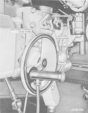
A closer view of the elevation handwheel is provided here. (Picture from TM 9-2350-201-12.)
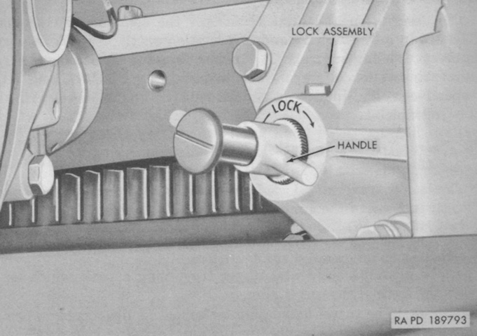
The turret traversing lock was positioning to the gunner's front. It was engaged by pulling the handle outward and turning it clockwise one quarter turn. It was released by pulling the handle outward and rotating a quarter turn counterclockwise. The lock was to be disengaged when the 76mm gun was secured in its travel lock or when the traversing electric motor was being used. M41A1s converted from M41s retained their original-style traversing locks. (Picture from TM 9-2350-201-12.)
The tank commander was provided with both traverse and elevation control with the Cadillac system. Traverse was accomplished by moving the butt of his handle in the desired direction; elevation was accomplished by moving the handle forward and depression by moving it to the rear. In contrast to the pulsing relay system, the gun control box with the Cadillac turret control system had on/off toggle switches for the 76mm gun, the coaxial machine gun, and the power elevation circuit. The elevation switch on the gun control box had to be activated before the TC could elevate the gun. (Picture from FM 17-80 Tanks, 76-mm Gun, M41 and M41A1.)
With the Cadillac traversing mechanism being self-contained at the gunner's station, the space around the turret slip ring box was used to stow more main gun ammunition. Twenty-one rounds were stowed in the M41A1's turret racks, compared to thirteen in those in the M41. (Picture from TM 9-2350-201-12.)
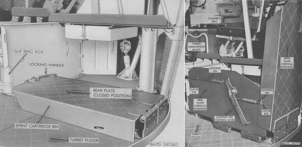
In M41A1s with Ordnance serial numbers of 1820 and above, the spent cartridge bin was a two-piece affair installed on the turret floor behind the 76mm gun that could handle eleven spent cartridges. To open the bin, the locking handle was rotated one quarter turn clockwise, which allowed the rear plate to be raised to vertical. The side plates were then raised, and the locking pin control lever was turned until the locking pins meshed with the clevis eyes. Stowage of the bin was a reversal of this process. (Picture from TM 9-2350-201-12.)
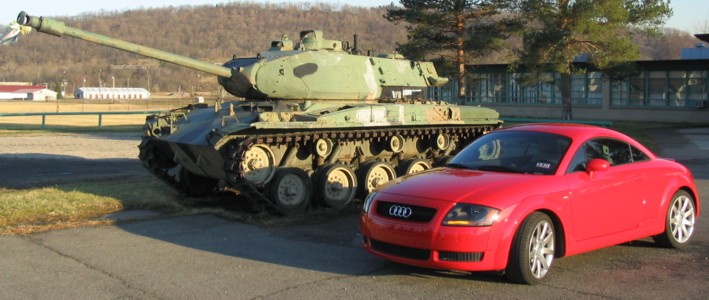
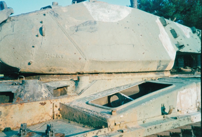
This tank is the subject of several of the following detail photos. It shares some features with the vehicle above, including angled fenders and mounting the auxiliary engine muffler (which is not present) on the front fender. The interior of the fender stowage box is visible as its cover is missing as well. The Audi TT provides some scale to the size of the vehicle.
The handle on the driver's hatch is obvious, and the circular opening is for installation of the M19 infrared periscope. Daytime view for the driver was provided by four M17 periscopes, which covered an arc of approximately 270°. The door lock can be seen at the top center of the photo, and the locking pins are welded to the front hull plate.
The area around the driver's hatch and periscope mounts was a casting welded to the hull. The glossy paint on this tank makes the contrast between the rolled and cast portions easier to discern.
The left-side position of the driver is apparent in this view of the tank's front hull. Lifting eyes and towing lugs are welded to the upper and lower plates, respectively, and the positions of the headlight mountings are visible. This tank is wired for the later-production headlight assemblies, which included an infrared blackout headlight for use with the M19 periscope. The aperture in gun shield's left-hand side is for the coaxial machine gun.
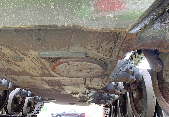
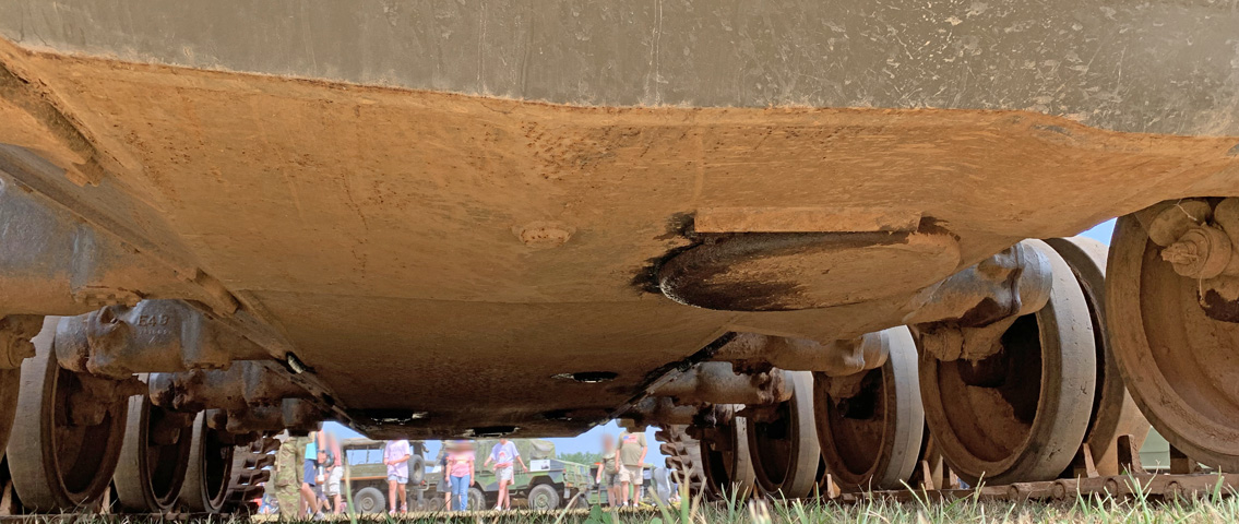
The driver's escape hatch was protected by a guard that was biased to the centerline of the hull, and an extension on the hull lower front plate provided some coverage to the outboard side. The extended lower hull under the driver can again be seen.
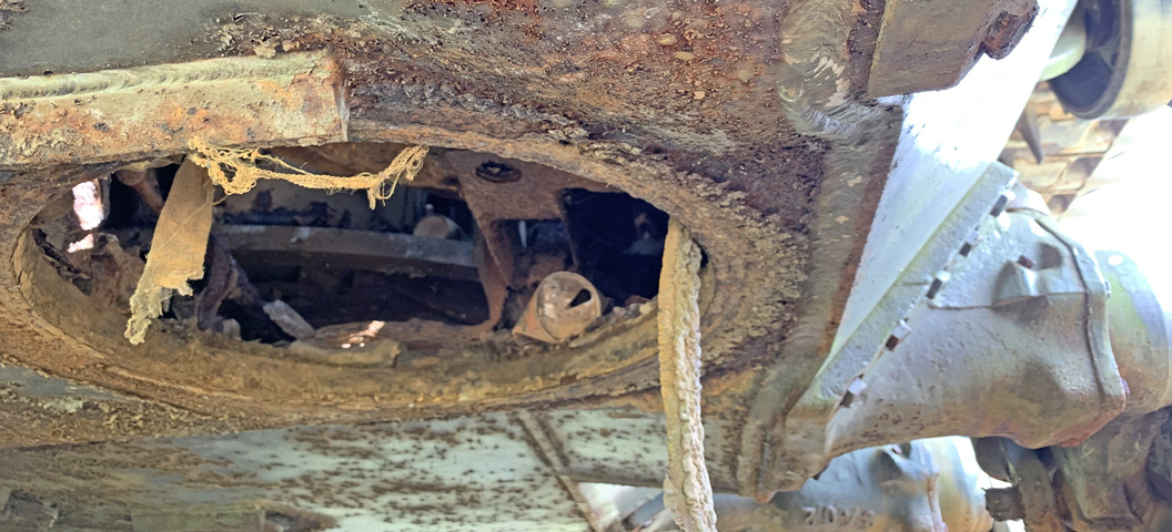
This tank is missing its hull escape hatch, allowing the thickness of the hull floor to be seen. The bottom of the driver's seat is visible above the opening, and the turret basket can be glimpsed in the background.
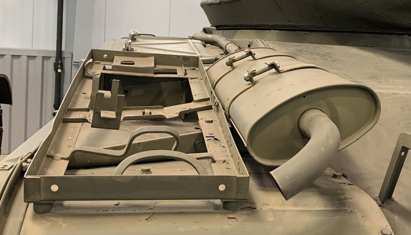
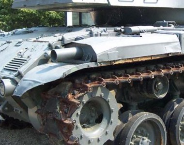
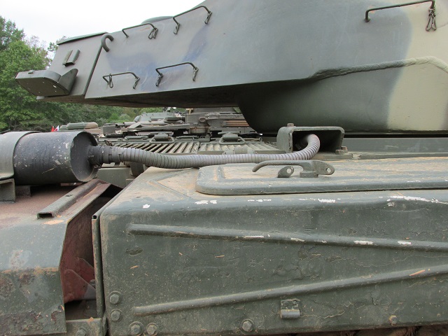
This right front view shows the location of the pioneer tool rack. Just inboard of the pioneer tool rack, a mounting clamp for the auxiliary engine muffler is visible. Behind this, snaking back to the rear of the tank, is the flexible exhaust tube that led from the auxiliary engine to its muffler.
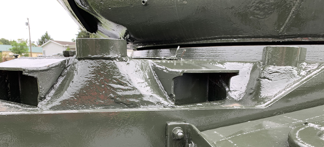
With the tool rack and muffler missing on this vehicle, the tool rack mounting points added to the fender and the modification made to the fender support to allow clearance for the auxiliary engine muffler are visible.
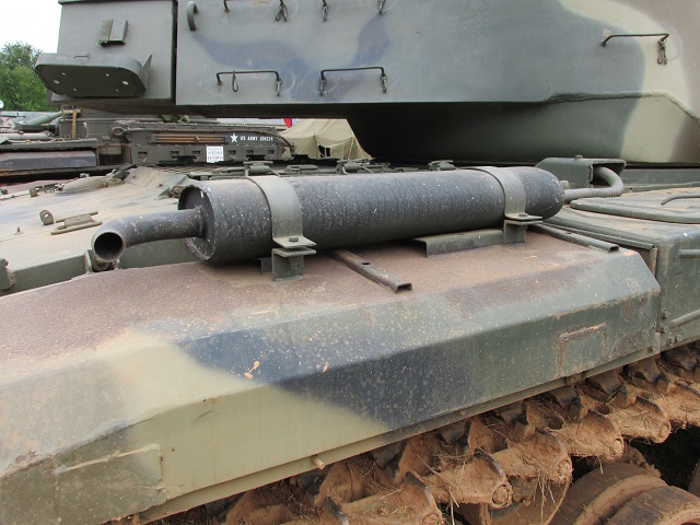
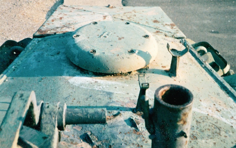
Featured in this picture is the auxiliary generator engine exhaust shroud. It was located at the right front of the main engine compartment, and its muffler was originally located to the rear on the main engine muffler, until it was realized that heat from the main engine muffler damaged the auxiliary muffler. The flexible exhaust tubing can be seen leading towards the front of the tank, where the auxiliary engine mufflers were then relocated. In front of the exhaust shroud is a fender stowage box; behind this is the right-hand main engine muffler shield.
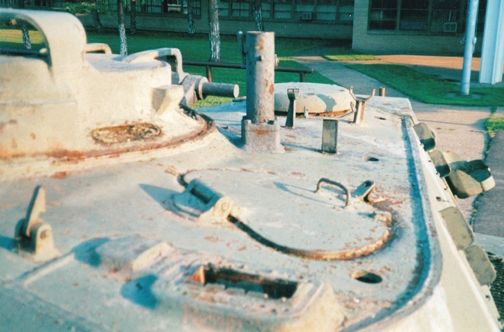
The travel lock for the 76mm gun is visible folded to the rear on the tank's left-side fender, and the main engine mufflers are obvious on each fender. The access cover in the middle of the centrally-placed transmission rear access door was for filling the transmission oil. The rear of the turret is dominated by the large stowage box. Fixtures on the bottom rear of the tank include towing lugs flanking the central towing pintle, and just inboard of the right-hand final drive is the interphone equipment case. The taillights are mounted just outside of the rear lifting eyes.
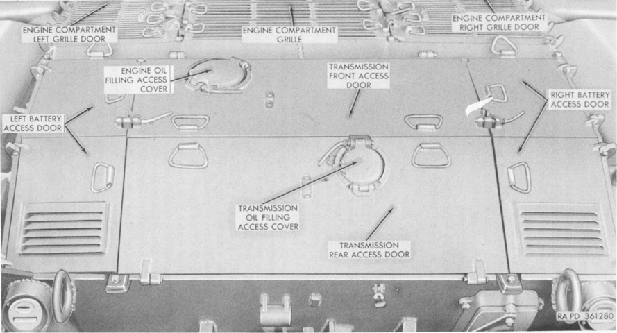
Various grilles and doors on the hull rear are labeled in this picture. The armored box for the infantry interphone can be better seen as well. (Picture from TM 9-2350-201-12.)
The compensating idler and first dual road wheels have been removed in this image. Track tension was adjusted by turning the adjusting nut in or out with a bespoke wrench. (Picture from TM 9-2350-201-12.)
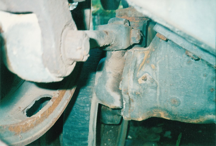
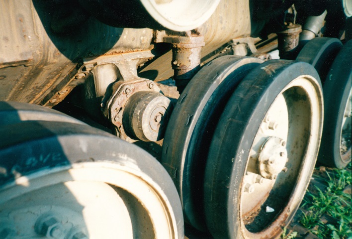
This picture illustrates the idler wheel connecting link assembly. The linkage transferred vertical motion of the front road wheels to the compensating idler wheels in order to keep the track tension constant. On tanks from Ordnance serial no.2612 and after, rubber tires were added to the compensating wheels, which necessitated adding an extra track shoe to each side.
This tank has a rubber tire on the idler wheel, and the connecting link assembly and track tension adjustment mechanism are more easily seen.
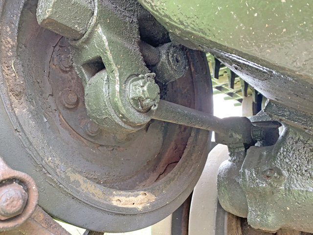
The road wheels on the M41 were mounted on trailing arms. These wheels are on the tank's left side, and behind the wheel itself is visible the volute spring bumper stop that limited wheel amplitude and prevented damage from over-rotation. To the rear, a shock absorber can be seen angling up from the last road wheel.
The second left dual road wheel has been dismounted, allowing a view of its hub and various components normally hidden behind the wheel. (Picture from TM 9-2350-201-12.)
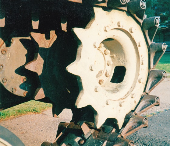
The 12-tooth rear drive sprocket is visible here, along with details of the T91E3 track. The track was center guide, single pin, and featured rubber pads on both the road surface and the inner surface of the track.
The low weld line characteristic of later-production tanks is visible on this vehicle. The weld line must angle upwards to meet the bottom of the turret bustle instead of going straight across the turret at the bustle level. The row of small bolts near the front of the turret was for attaching a canvas gun mantlet cover, and the hook on the fender stowage box was to help hold the tow cable which was stowed on the tank's left side. The fourth driver's periscope is also visible.
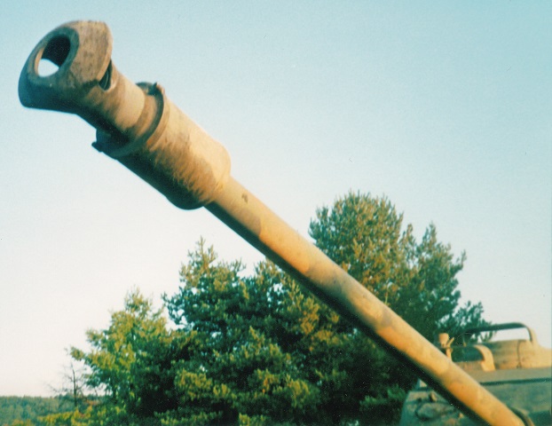
The muzzle brake of this tank is the early cast variety. Just behind this is the bore evacuator for the 76mm gun.
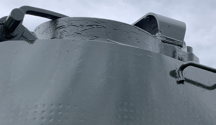
The commander's periscope guard was welded to the cupola. Note also the marks on the cupola casting.
The commander's and gunner's periscope guards dominate this view of the tank's roof. Mounts for the .50cal M2HB machine gun are positioned between the commander's cupola and gunner's periscope, and also to the left side of the TC's cupola. Later tanks moved the MG mount to a more serviceable position to the left front of the TC's cupola. The gunner's periscope guard has a notch in its right rear to allow clearance for the machine gun and pintle.
The notch in the gunner's periscope guard is seen from below on the left and with a dummy machine gun mounted on the right.
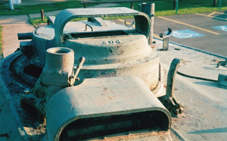
The opening for the loader's periscope is closest to the foreground in this image, and his hatch and hatch lock are visible as well. The commander's cupola was ringed at the bottom by five vision blocks facing to the sides and rear, and an M20 periscope provided forward view. The circular holes in the vehicle's roof were for antenna mounts, and the stowage brackets for the disassembled .50cal machine gun are also present on the roof.
At the very rear of the turret, behind the vehicle's radio set, was an air blower. This helped to exhaust any main gun propellant fumes that the bore evacuator did not take care of, and also those generated by the coaxial machine gun. Attached to the rear of the turret is a large stowage box, and a mount for a 5gal (19L) can is visible on each side of the turret.
Looking across the 76mm gun from the loader's side, the gunner's traverse wheel and gun control box are visible, and the spatial relationship between the gunner's position and the commander's power control handle can be seen. The replenisher on the 76mm gun mount shows evidence of leaking, and the elevation mechanism is visible on the opposite side of the gun mount.

The breech of the 76mm gun is on the right of the picture, and the commander's seat is visible to the rear. On the rear turret floor would normally be a spent cartridge bin for 76mm casings, but this has apparently been removed from this vehicle. (Note: If those are your pants, please email me; I have to hear this story.)
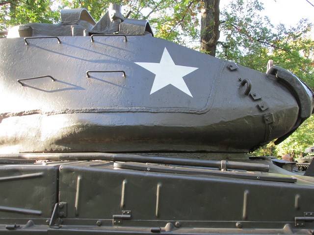
This tank is topped by an earlier-production turret with the characteristic high weld line that runs straight back to the turret bustle. The remains of the pipe for the auxiliary engine muffler can be seen snaking forward toward the front fender.
