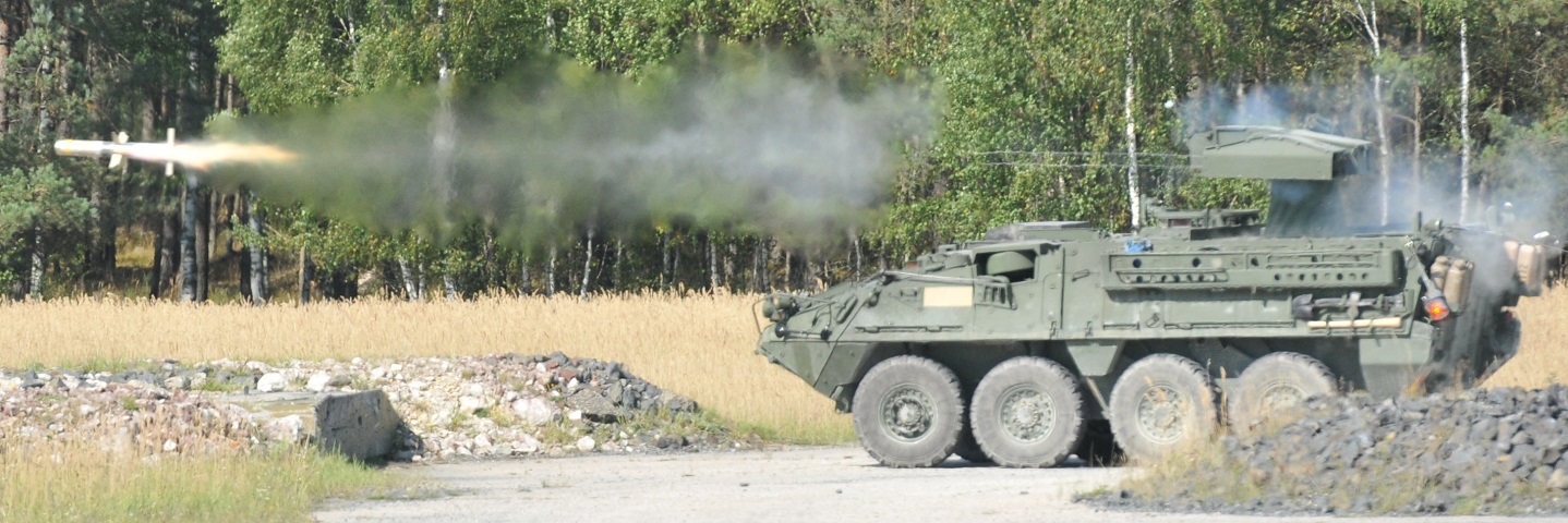
Antitank Guided Missile M1134 Stryker.

The ETS on this vehicle is raised and in action. The missile cannot be fired unless the ETS is raised and locked, and the loader's roof hatch has a switch to prevent firing if it is open. Note the control wires trailing from the missile. This vehicle is from Reaper Troop, 4th Squadron, 2nd Cavalry Regiment. (Picture taken 29 Aug 2012 by SPC Joshua Edwards; available from Defense Video & Imagery Distribution System.)
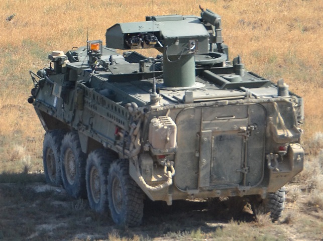
The reloading hatch in the roof behind the ETS can be glimpsed in this image, as well as the electrical connections to the training devices in the missile tubes. Unlike the vehicle above, the dust cover for the ETS mast has not been erected. This machine belongs to 1st Squadron, 14th Infantry Regiment, 3rd Stryker Brigade Combat Team. (Picture taken 14 Aug 2014 by SSG Chris McCullough; available from Defense Video & Imagery Distribution System.)
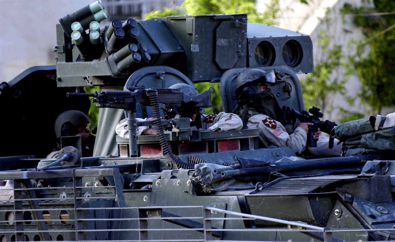
The smoke grenade launchers on the ETS are visible from this angle, and the vehicle commander's machine gun is mounted. Behind the ETS, the loader can be seen standing in his open roof hatch to the rear. This vehicle is fitted with slat and applique armor. (Picture taken 2 Aug 2002 by SPC Gretel Sharpee; available from Defense Video & Imagery Distribution System.)
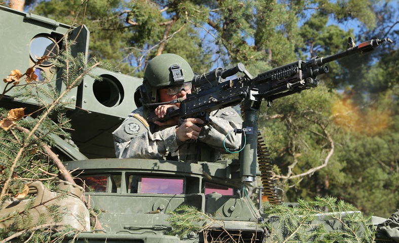
Vehicle commander 1LT Elliott Boltz of Reaper Troop, 4th Squadron, 2nd Cavalry Regiment is engaging opposing forces with blank ammunition in this image. Note the open door on the ETS behind him, which protects the missile optics when not in use. His machine gun would have to be lowered before the missiles are fired. (Picture taken 15 Apr 2015 by SPC John Cress, Jr.; available from Defense Video & Imagery Distribution System.)
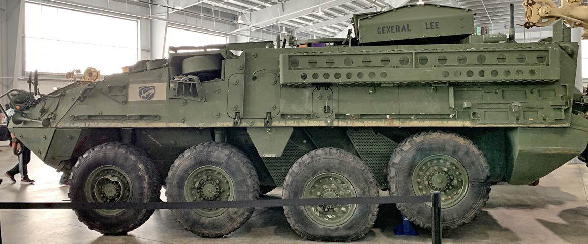
The ETS is stowed on this machine, and the height difference can be contrasted with the vehicles above. The vehicle's winch protrudes from the recess above the second wheel, and an escape hatch is visible in the hull side between the second and third wheels. A small hatch providing access to slave receptacles is above the third wheel.

Front and rear views of the winch are provided on the left and right, respectively.
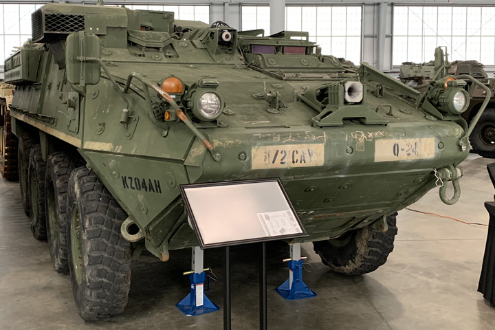
From the front, the lowered ETS is barely discernible. The driver's thermal viewer was mounted to the right of his hatch, and the outlet for the winch cable is prominent on the hull's nose.

A closer look at the driver's hatch and thermal viewer is provided here. The engine exhaust deflector is visible on the extreme left of the image, and further back can be seen the commander's cupola and the two missile apertures in the ETS.

The smoke grenade launches on the ETS are visible in this image, and the gunner's hatch beside the commander's cupola can also be seen. The vehicle's winch was found under the large protrusion behind the driver's hatch.

The engine exhaust deflector is at the right of this picture, with the winch in the background and the driver's hatch to the right. A wire cutter is folded forward onto the winch cover.
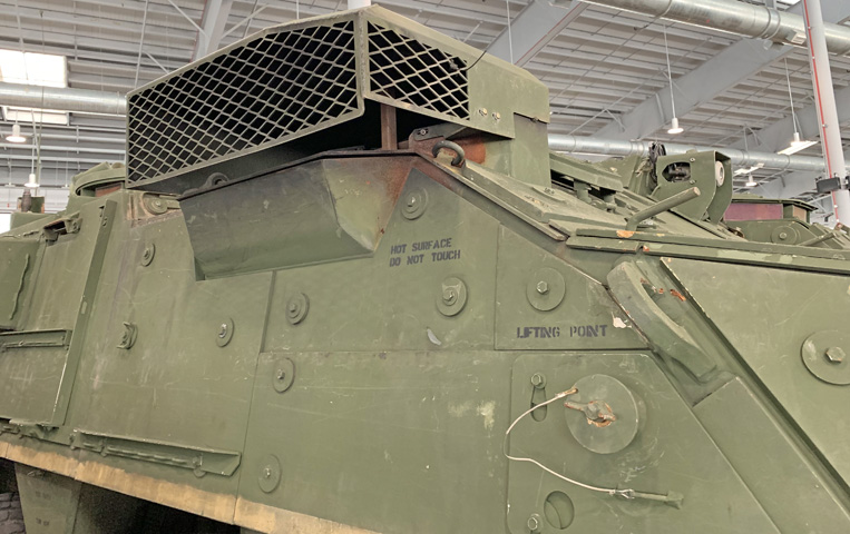
The exhaust deflector assembly re-routed the engine's smoke and fumes to a more downward angle.
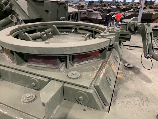
The rail for the commander's machine gun ringed his hatch. Springs were present to ease the load of opening the hatch.
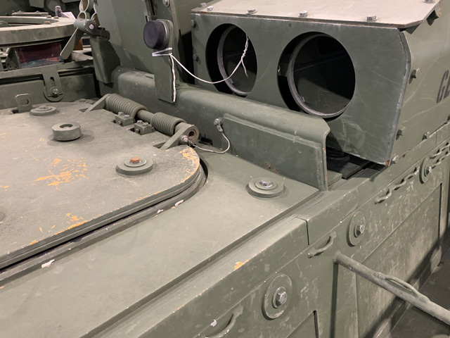
The fronts of the missile tubes in the stowed ETS are shown in this image. The gunner's hatch is present in the roof to the front, and a rubber stop was provided to the rear. Note the visible thickness of the applique armor on the gunner's hatch.
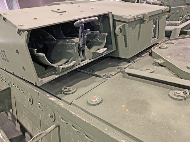
The rear of the ETS is detailed here, with the loader's hexagonal hatch visible to the right.
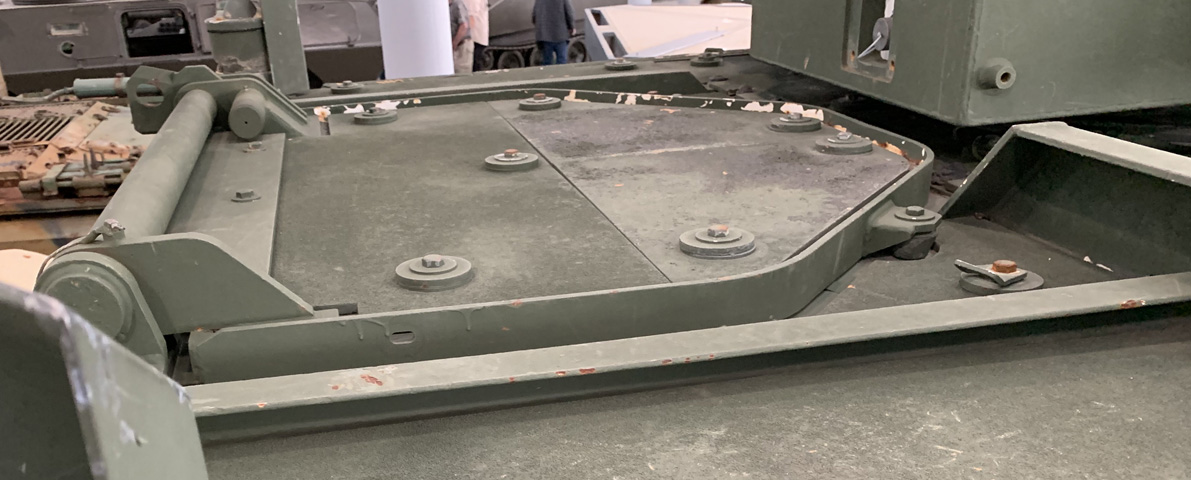
The loader's rear roof hatch is isolated in this image.
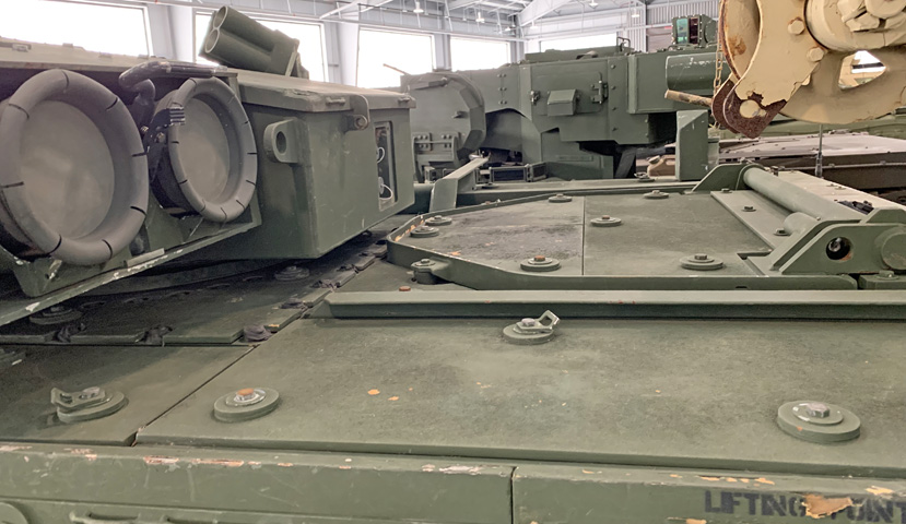
The loader's hatch and rear roof are seen from the opposite angle.
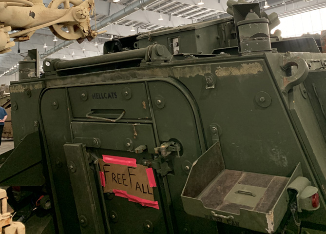
The ramp for the passenger compartment dominates the hull rear. Above the ramp on the roof can be seen the hinges and spring for the roof hatch used for reloading the TOW missiles. Antenna mounts are present on the rear corners of the roof, and racks for water or fuel cans flank the entrance ramp.

This vehicle has been equipped with the Driver's Enhancement Kit (DEK), which was 970lb (440kg) of armor added below the driver's position to improve protection against mines or improvised explosive devices.

The DEK extended under the hull as seen here. Details of the front left suspension are also visible.
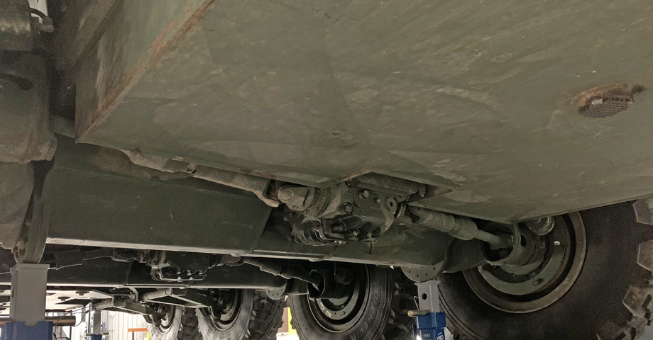
The underside of the rear of the vehicle is pictured in this image. Power was transmitted to the wheels via four multiple-disc limited slip differentials. Note that the front four wheels used wishbones, while the rear four were mounted on trailing arms.

The rear two suspension units were protected with perforated shields.

The hull near the wheels shows signs of heavy rubbing. These are the two left front wheels; wear has occurred above both, ahead of the front wheel, and on the hull side between the wheels.