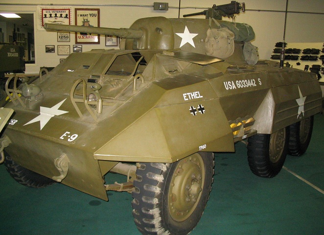
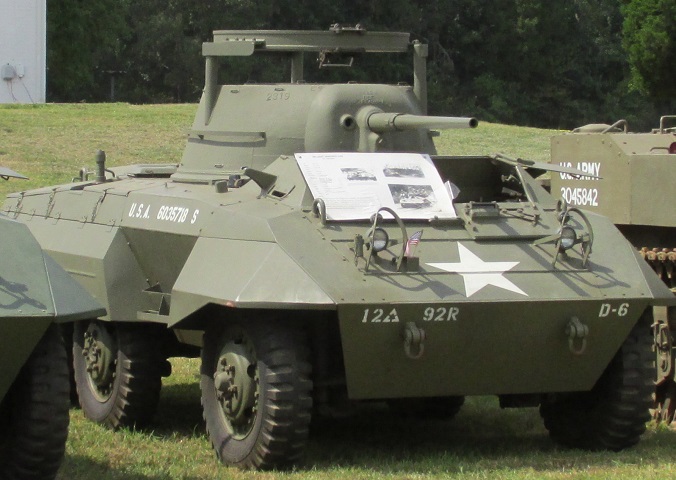
Light Armored Car M8 Greyhound at the World War II Vehicle Museum and Learning Center.
"Ethel" is an early-production M8 and features mine racks between the first and second road wheels. The aperture for the gunner's M70D telescope is visible on the near side of the gun shield; the coaxial MG is on the opposite side of the 37mm gun. The drivers are provided with two hatch covers, and on this vehicle the driver's hatch covers are open. The top hatch cover swings to the outside of the vehicle, while the front hatch cover swings down onto the front slope. The front hatch covers feature both a direct vision slot and a periscope, and there is another direct vision slot outboard of each driver. The vehicle's siren is just inboard of the right-hand headlight group. The .50cal MG is mounted on the Ford-designed folding mount.
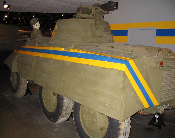
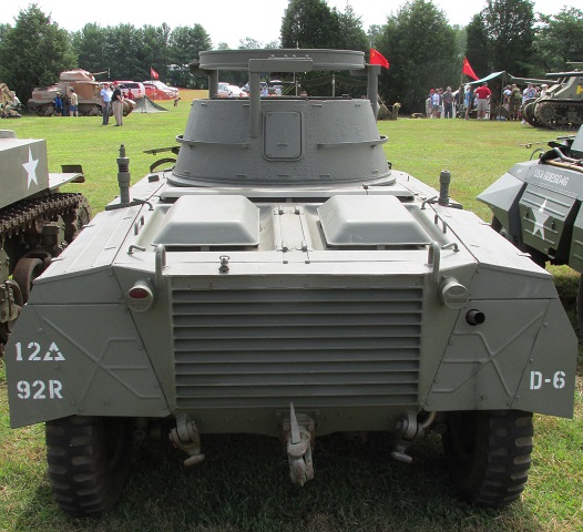
This late-production vehicle features stowage bins between the front and center axles instead of the earlier mine racks. The front leaf spring can also be contrasted to the smaller spring on the above car.
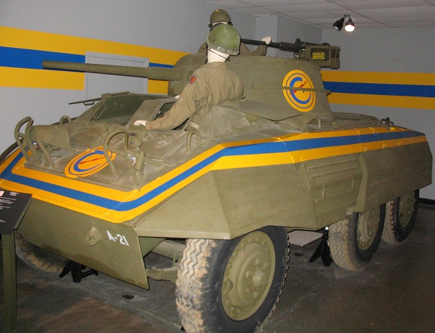
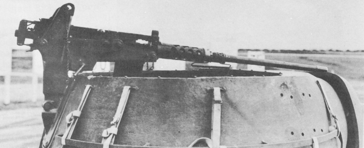
The positioning of the folding .50cal MG mount can be seen here; it could be raised for action. It was attached to a plate in the turret rear that was removed to allow the 37mm gun to be taken out of the vehicle more easily.
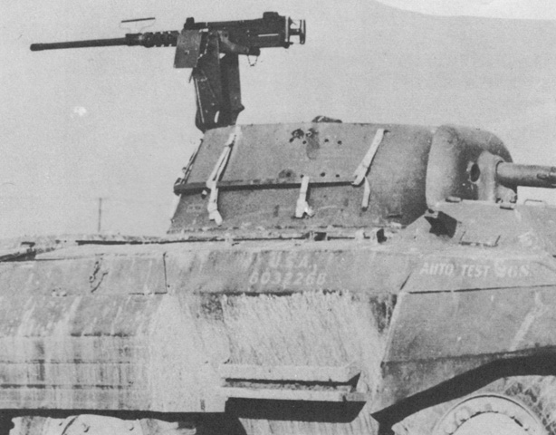
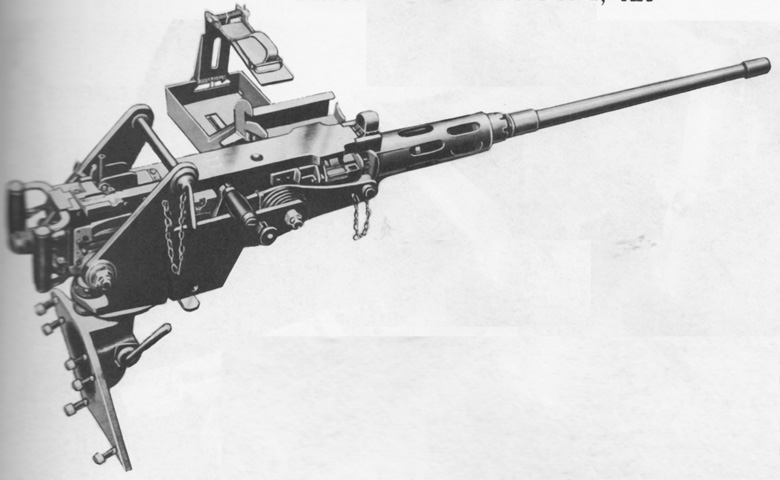
The D67511 folding pintle antiaircraft bracket mount is shown with the machine gun in firing position. The mount consisted of a pintle mount on the turret rear, the machine gun cradle with ammunition tray, the machine gun pintle, and the folding yoke that permitted the gun to be elevated for firing or lowered for stowage. (Picture from Weapon Mounts for Secondary Armament.)
The machine gun has been lowered to its traveling position, but note that the barrel lock is not installed. (Picture from Weapon Mounts for Secondary Armament.)
The mount D67511 was modified into the folding pintle bracket antiaircraft mount D7058824, which used a different ammunition tray and featured a counterbalance spring connecting the cradle and support assembly. Elevation was from +85° to -12°, and traverse was a full 360°. (Picture from Weapon Mounts for Secondary Armament.)
This car is fitted with the M49C ring mount instead of the Ford-designed machine gun mount, and can be contrasted with the other vehicles on this page.
The machine gun ring mount was welded off-center to the rear of the turret to adjust for the removable plate that facilitated extraction of the 37mm gun.
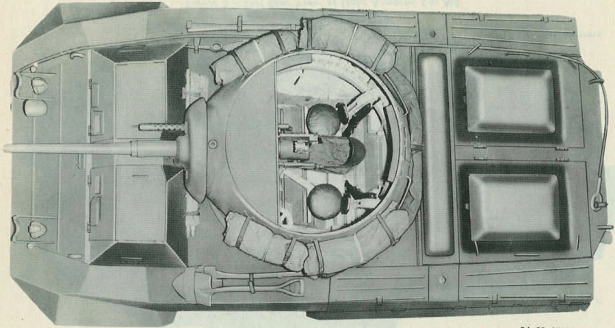
The open turret is highlighted in this view. Seats for the turret crew flank the 37mm gun, and pioneer tools (axe and shovel on the left, disassembled mattock on the right) can be seen stowed on the fenders between the front and intermediate axles. A towing cable is strung along the hull's right side. The handles and hinges for the engine compartment doors are visible on the rear of the hull. A 12' x 12' (3.7m x 3.7m) paulin is stowed on the rear of the turret, and four blanket rolls for the crew are hanging off the turret sides. Between the turret and the engine compartment doors is the fuel tank cover; the filler was under a hinged portion of the right-hand side of the cover. Openings for antenna mounts flank the fuel tank cover. (Picture from TM 9-743 Light Armored Car M8.)
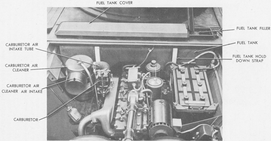
The location of the fuel filler can be seen with the cover raised. The engine doors and their hinge plate have been removed. The 12-volt storage battery is visible in the front right corner of the engine compartment. (Picture from TM 9-743 Light Armored Car M8 and Armored Utility Car M20.)
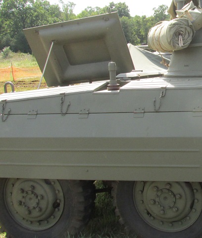
The engine compartment hatch is open on this vehicle, allowing a look at the construction of its underside.
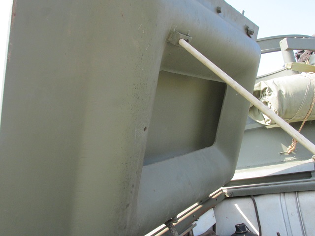
A closer look at the engine compartment hatch is shown here.
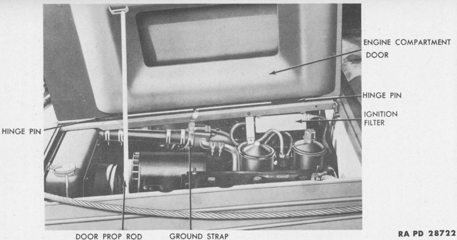
Each engine compartment door had two hinges, and a bonding strap connected each door to the hinge plate. (Picture from TM 9-743 Light Armored Car M8 and Armored Utility Car M20.)
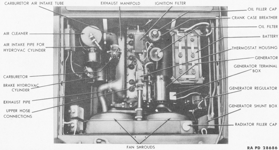
The installed engine is shown here with the engine compartment doors and hinge plate removed. The engine weighed 750lb (340kg), displaced 320in³ (5200cm³) with a 6.5:1 compression ratio, a 4" (10cm) bore, and a 4.5" (11cm) stroke. The engine was ungoverned, and responsibility to prevent over-revving resided solely with the driver. (Picture from TM 9-743 Light Armored Car M8 and Armored Utility Car M20.)
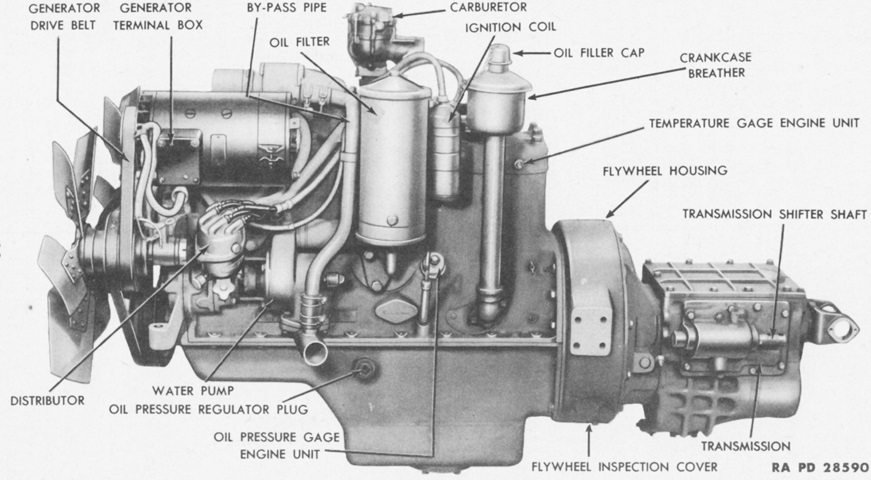
The right sides of the engine and transmission are labeled in this picture. The flywheel end of the engine was considered the front, and the left and right sides of the engine matched the left and right sides of the car. With the transmission and accessories, the engine weighed 1030lb (467kg). (Picture from TM 9-743 Light Armored Car M8 and Armored Utility Car M20.)
Although the engine was basically similar to that found in the scout car M3A1, the two vehicles used different accessories, making a direct swap as an assembly impossible. (Picture from TM 9-743 Light Armored Car M8 and Armored Utility Car M20.)
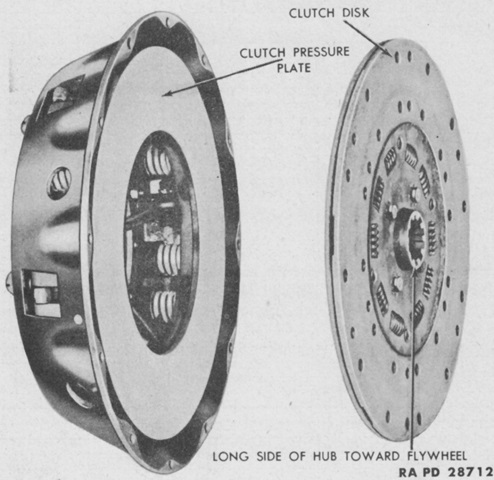
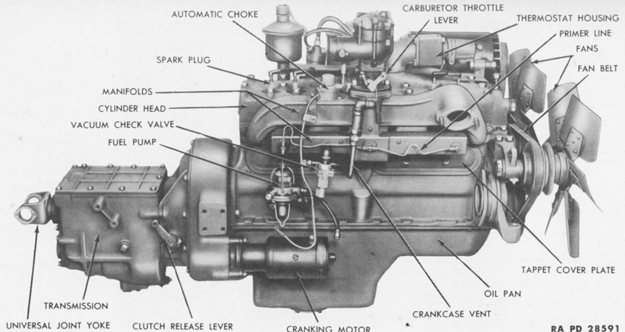
The Long Manufacturing Co. 12C B-C dry, single-plate clutch was hydraulically controlled. The friction facings were 12" (30cm) in diameter. (Picture from TM 9-743 Light Armored Car M8 and Armored Utility Car M20.)
The gear ratios for the transmission were 6.499:1.0 for first gear, 3.543:1.0. for second, 1.752:1.0 for third, 1.000:1.0 for fourth, and 6.987:1.0 for reverse. (Picture from TM 9-743 Light Armored Car M8 and Armored Utility Car M20.)
The transmission is shown here from the top with its cover removed. (Picture from TM 9-1743 Ordnance Maintenance--Power Train, Suspension, Hull, and Turret for Light Armored Car M8 and Armored Utility Car M20.)
The Warner Gear G5 transfer case offered high and low speed ranges, the ability to declutch the front axle, and a parking hand brake on the unit's front side. (Picture from TM 9-743 Light Armored Car M8 and Armored Utility Car M20.)
The interior of the transfer case can be seen here. (Picture from TM 9-1743 Ordnance Maintenance--Power Train, Suspension, Hull, and Turret for Light Armored Car M8 and Armored Utility Car M20.)
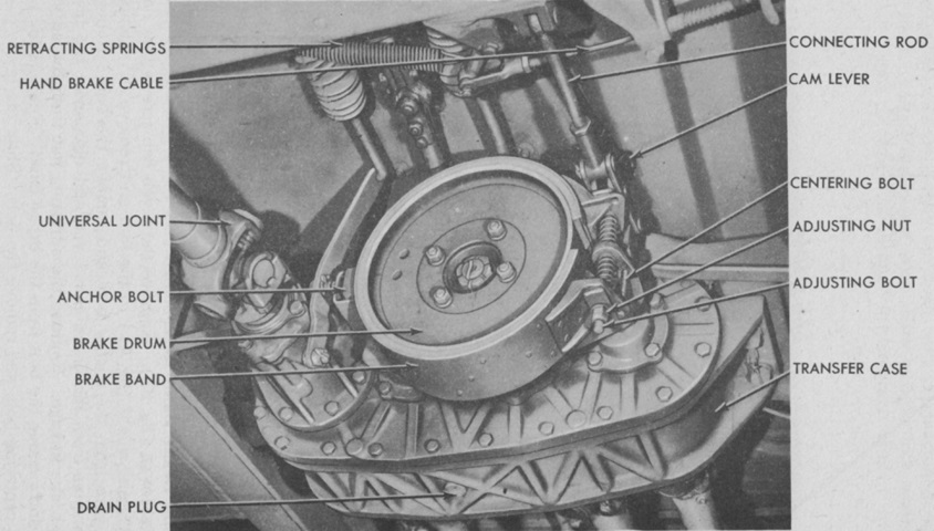
The transfer case is shown installed in this picture. The external contracting hand brake was 3" (7.6cm) wide, 9.5" (24cm) in diameter, with a lining length of 24.62" (62.53cm) for a total lining area of 123.2in² (794.8cm²). (Picture from TM 9-743 Light Armored Car M8 and Armored Utility Car M20.)
The rear of the installed transfer case is seen here. (Picture from TM 9-743 Light Armored Car M8 and Armored Utility Car M20.)
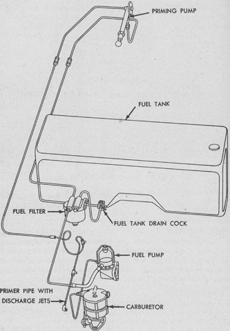
The fuel system is diagrammed in this image. (Picture from TM 9-743 Light Armored Car M8 and Armored Utility Car M20.)
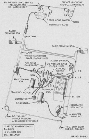
The car used a 12-volt electrical system, shown in this schematic. A Ford 750 watt, 12 volt, 50 ampere generator was mounted to the engine. (Picture from TM 9-743 Light Armored Car M8 and Armored Utility Car M20.)
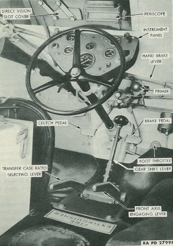
A view of the driver's compartment is shown here. Note the carbine stowed to the driver's left and the spot for the portable 4lb (1.8kg) CO2 fire extinguisher bottle near the bottom of the image. When the transfer case ratio selecting lever was in the down position, high gear for the transfer case was selected. When this lever was swung up, the transfer case was shifted to low gear. Before engaging the low ratio, the front axle was to be engaged by swinging the front axle engaging lever up. The vehicle was to be traveling at no more than 5mph (8kph) when changing from the high to low ratio. (Picture from TM 9-743 Light Armored Car M8.)
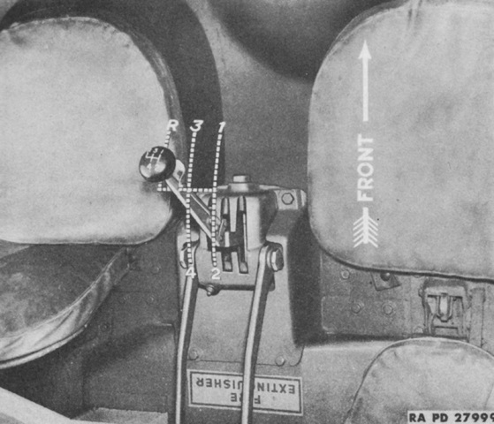
The shift pattern for the transmission would take some practice for modern drivers. (Picture from TM 9-743 Light Armored Car M8 and Armored Utility Car M20.)
A compass was mounted in front of the assistant driver's seat. Just beyond the compass is the periscope in the assistant driver's closed front hatch cover.
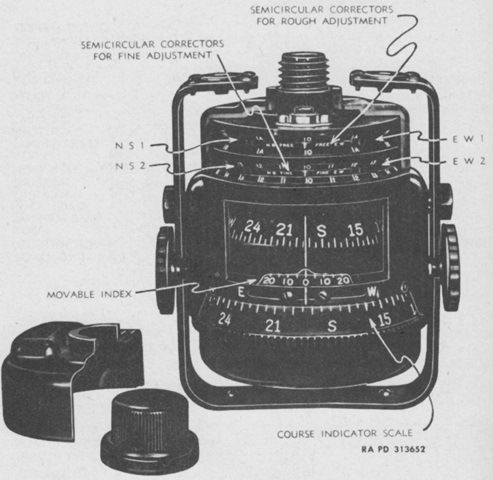
The assistant driver's Sherill A.E.G. compass is detailed here. (Picture from TM 9-743 Light Armored Car M8 and Armored Utility Car M20.)
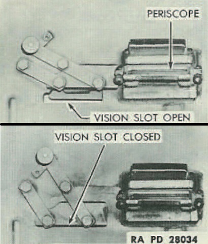
For forward vision, the drivers were provided with a shutterable direct vision slot as well as a periscope. (Picture from TM 9-743 Light Armored Car M8.)
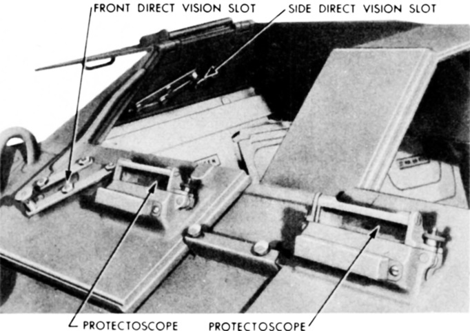
Another view of the drivers' vision devices, including the assistant driver's side direct vision slot, is shown here. (Picture from TM 9-1743 Ordnance Maintenance--Power Train, Suspension, Hull, and Turret for Light Armored Car M8 and Armored Utility Car M20.)
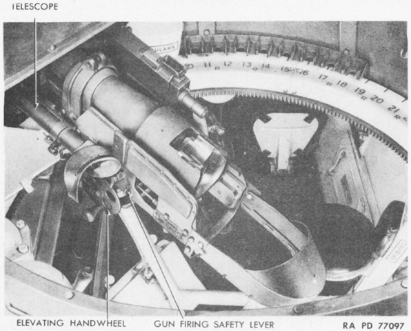
The left side of the gun is shown in this image. (Picture from TM 9-743 Light Armored Car M8 and Armored Utility Car M20.)
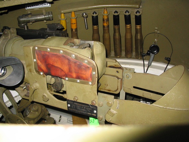
The right side of the turret is illustrated in this image. Thirty-seven millimeter ammunition lines the far side, and the black coaxial machine gun can be seen on the opposite side of the combination gun mount. A total of sixteen 37mm rounds were stowed in clips in the turret. The gunner's sighting telescope is visible, and the top half of his elevation handwheel is near the bottom of the picture.
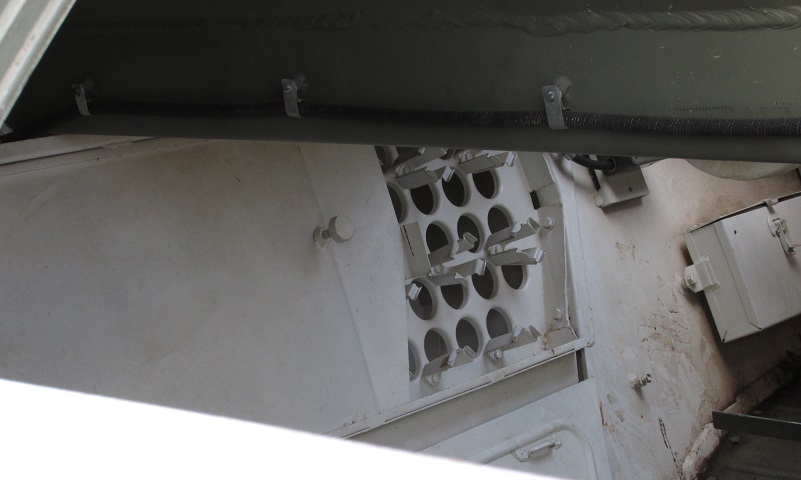
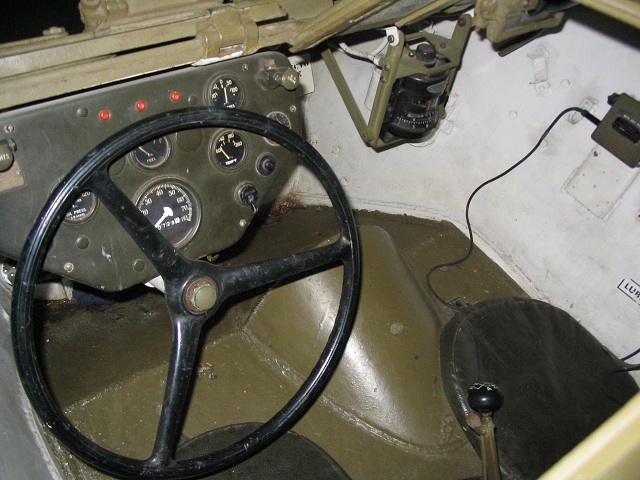
This view is looking in through the open driver's hatch. The remaining 64 rounds of 37mm ammunition were stowed in the right-hand sponson behind a sliding door.
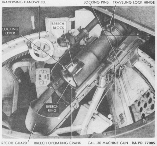
The opposite side of the ordnance is labeled. This car is equipped with the early single-speed traverse mechanism. (Picture from TM 9-743 Light Armored Car M8 and Armored Utility Car M20.)
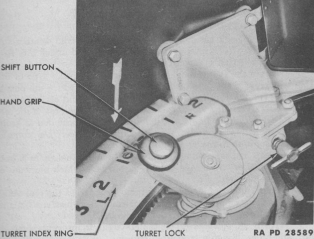
The later two-speed traversing mechanism is highlighted in this picture. When the shift button was depressed, the mechanism was changed into high gear. When the button was released, low gear was again automatically engaged. (Picture from TM 9-743 Light Armored Car M8 and Armored Utility Car M20.)
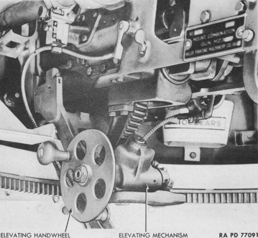
A closeup of the elevation mechanism is provided by this image. (Picture from TM 9-743 Light Armored Car M8 and Armored Utility Car M20.)
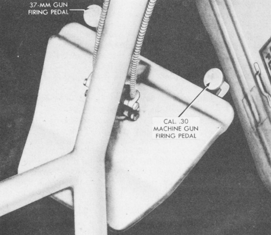
The 37mm gun and coaxial machine gun were fired by means of separate foot triggers. (Picture from TM 9-743 Light Armored Car M8 and Armored Utility Car M20.)
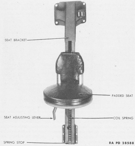
The gunner and commander were both provided with adjustable seats in the turret. (Picture from TM 9-743 Light Armored Car M8 and Armored Utility Car M20.)
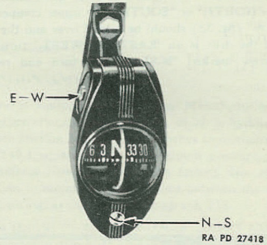
A compass was also provided in the turret above the combination gun mount. (Picture from TM 9-743 Light Armored Car M8.)
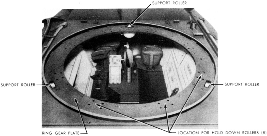
An overview of the hull interior is provided here with the turret removed. Eight hold-down rollers and three support rollers secured the turret and allowed it to traverse. (Picture from TM 9-1743 Ordnance Maintenance--Power Train, Suspension, Hull, and Turret for Light Armored Car M8 and Armored Utility Car M20.)
The hold-down rollers engaged with the plates that made up the turret index ring. (Picture from TM 9-1743 Ordnance Maintenance--Power Train, Suspension, Hull, and Turret for Light Armored Car M8 and Armored Utility Car M20.)
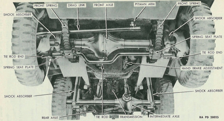
This view is looking toward the rear of the vehicle. The Timken-Detroit Axle Co. front axle used split-type housings and had a ratio of 6.66:1. (Picture from TM 9-743 Light Armored Car M8.)
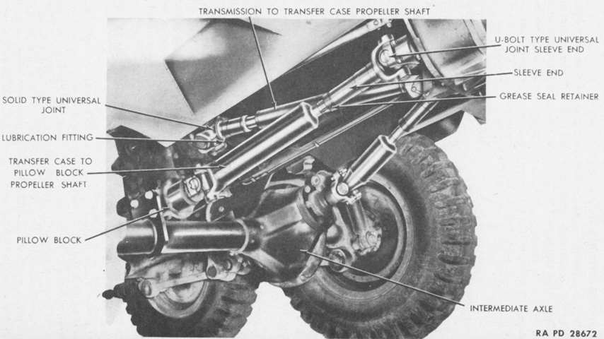
The shafts and joints between the front and intermediate axles are shown here. The pillow block provided a connection through which the power traveled to the rear axle. (Picture from TM 9-743 Light Armored Car M8 and Armored Utility Car M20.)
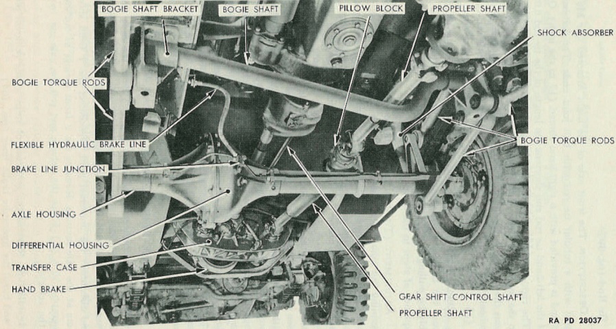
This view is similar to the one above, but is looking forward from the vehicle's left rear. The intermediate and rear axles were standard Ford 1½-ton (1,360kg) truck rear axle housings and differentials with ratios of 6.66:1. Components of the axles were longer than standard axles to account for the size of the car, however. (Picture from TM 9-743 Light Armored Car M8.)
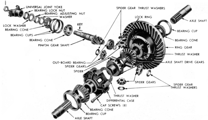
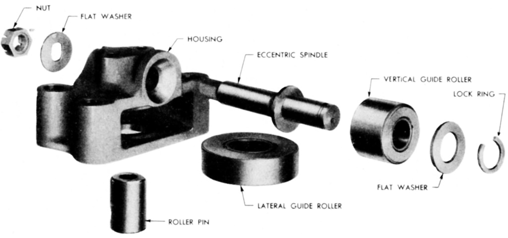
An exploded view of the rear axle is offered here. (Picture from TM 9-1743 Ordnance Maintenance--Power Train, Suspension, Hull, and Turret for Light Armored Car M8 and Armored Utility Car M20.)
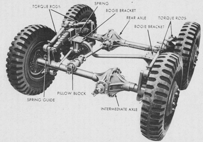
The rear bogie allowed the rear wheels to raise and lower independently of each other in response to terrain, and was mounted on two bogie brackets, one attached to each side of the hull. The torque rods maintained the distance between the two rear axles and between the axles and hull. The torque rods and bogie bracket were the media through which the driving force was transmitted to the hull from the axles. (Picture from TM 9-743 Light Armored Car M8 and Armored Utility Car M20.)
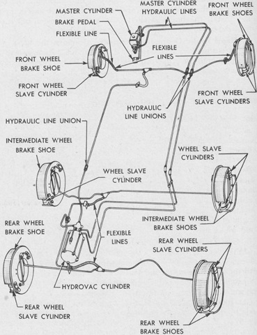
The service brake system is sketched in this diagram. Each wheel was arrested by an hydraulically-operated 2-shoe internal expanding brake. Each brake had two slave cylinders, making each shoe a primary shoe. (Picture from TM 9-743 Light Armored Car M8 and Armored Utility Car M20.)
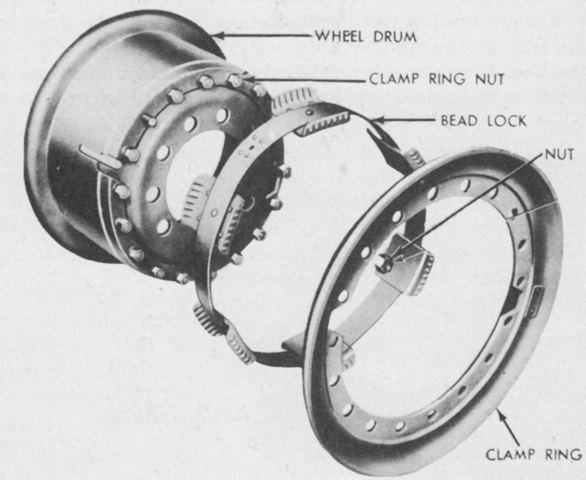
The divided-rim wheels were 20" (51cm) in diameter, and the rims were 6.00" (15.2cm) wide. A bead lock secured the tires to the rims. The front tires were inflated to 60psi (4.2kg/cm²), and the rear to 50psi (3.5kg/cm²). (Picture from TM 9-743 Light Armored Car M8 and Armored Utility Car M20.)
