High Speed Tractor M8A1.
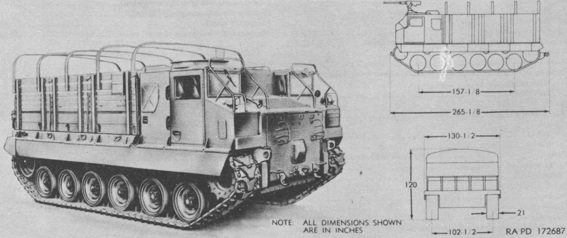
The high speed tractor M8A1 utilized the powertrain and suspension components of the 76mm gun tank M41, however an extra road wheel station was added for the tractor. The two-man crew was separated by the engine compartment, and the ring mount for the .50cal machine gun was over the assistant driver's station. Towing pintles were provided at both the front and rear. The inner dimensions of the body were 157" (399cm) long, 114½" (290.8cm) wide, and 62¼" (158.1cm) high for a total of 650ft³ (18.4m³) of cargo space. (Picture from TM 9-500 C3 Data Sheets for Ordnance Type Materiel.)
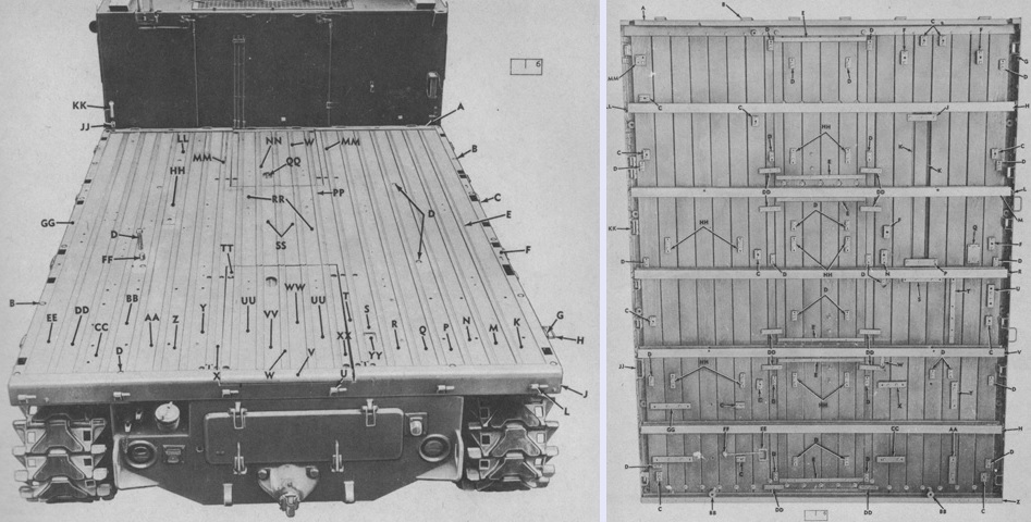
Upper and lower views of the cargo platform are provided here. Besides miscellaneous cargo and ammunition, special kits could be installed depending on the tractor's intended use in its end unit. Loading height was 57¾" (146.7cm). (Picture from ORD 9 SNL G-252 List of All Service Parts of Tractor, Full Tracked, High Speed: M8A1.)
The body kit T48 loaded on the cargo bed on this tractor, for example, was used when towing the 75mm antiaircraft gun M51 Skysweeper. This kit provided for carriage of the gun crew, its equipment, and forty-eight 75mm rounds. (Picture from ORD 9 SNL G-252 List of All Service Parts of Tractor, Full Tracked, High Speed: M8A1.)
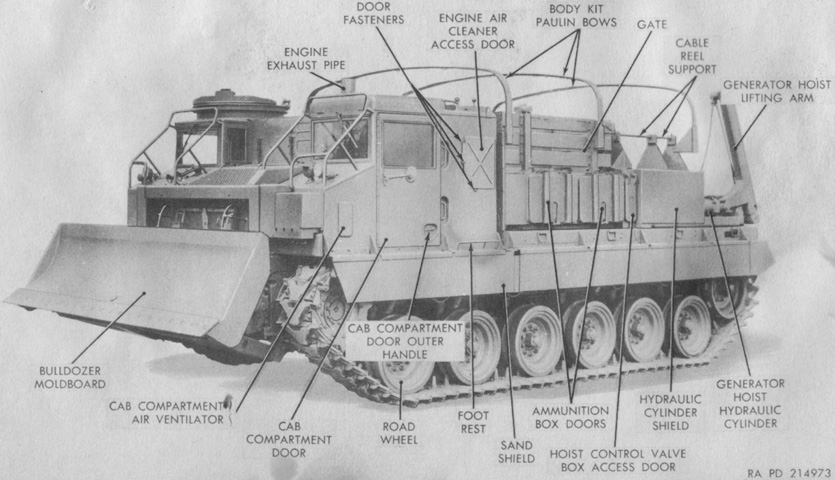
On 29 June 1951 the Ordnance Committee required that a bulldozer be equipped on M8A1s being used as prime movers for the Skysweeper. The tractor mounting bulldozer M5 was of light steel construction and connected to the hull by push beams and tilt arms similar to contemporary tank mounting bulldozers. Two double-acting hydraulic cylinders raised or lowered the moldboard, and carrying hooks were operated from the driver's position to stow the moldboard for travel. Since the bulldozer blocked access to the vehicle powerplant, the bulldozer linkage and hydraulic cylinders were attached to the hull by a bracket arrangement so that disassembling the main bulldozer unit only required removing four pins and disconnecting four hoses. Support stands built into the moldboard would hold the pushbeams, tilt arms, brackets, and cylinders at the same relative position as when they were disconnected. The bulldozer was intended only to prepare emplacements for the tractor's towed gun, and extensive use as a construction tool would shorten the life of the tractor's suspension components. Seven hundred eighty-six M5 bulldozers were procured.
The bulldozer kit increased the tractor's weight by 4,000lb (1,800kg) including oil; length of the tractor with the bulldozer installed was 301" (765cm). The moldboard was 129½" (328.9cm) long and 34⅞" (88.583cm) high, and the reversible cutting blade was ¾" x 8" x 130¼" (1.9cm x 20cm x 330.84cm). The cutting edge presented a 60° angle to ground level. The moldboard could be lifted 32-5/16" (82.0738cm) above the ground and dropped 7⅛" (18.10cm) below ground, and the carrying height of the moldboard in the carrying hooks was 30-5/16" (76.9938cm). The tractor's angle of approach 20°30' with the moldboard in the carrying position and 21°30' with the moldboard at its highest position. The moldboard's maximum rate of lift was 18.00"/sec (45.72cm/sec) at 2,800 main engine rpm. The vehicle operated at 1-3mph (2-5kph) in low gear when bulldozing, and it was recommended not to exceed 15mph (24kph) with the bulldozer mounted. (Picture from TM 9-7420 Operation and Organizational Maintenance Cargo Tractor M8E2.)
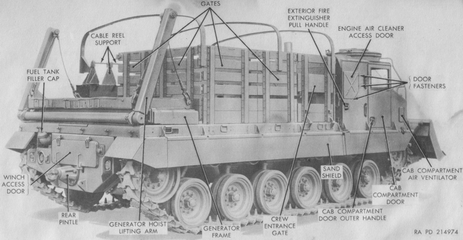
The tractor body kit T48 included a generating set M18, and an hydraulically operated hoist was at the rear for loading and unloading the generator, ammunition, or other cargo. The kit also incorporated stowage compartments and bench seats for seven of the gun crew. (Picture from TM 9-7420 Operation and Organizational Maintenance Cargo Tractor M8E2.)
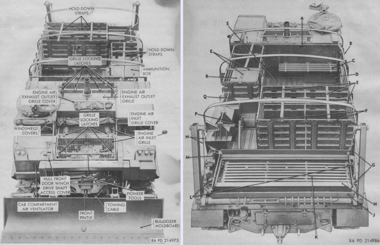
Front and rear views from above are provided of a tractor with the T48 body kit. The drivers sat on either side of the powerplant. The hull front door winch access cover was raised to operate the winch that lowered and raised the hull front door in order to access the power plant. It was a ¾" square socket, and at least 30" (76cm) of socket extensions were necessary to reach the ratchet. The legend for the right image is: A. Tractor body kit name plate. B. Crew entrance gate. C. Seat. D. Stowage box. E. Holddown straps. F. Gates. G. Hoist lift cable hooks. H. Generator base. J. Generator frame. K. Cargo pallet. L. Frame holddown. M. Hoist hydraulic cylinder. N. Hoist lift cables. P. Spare tire support. Q. Cable reel support. R. Ammunition box. S. Cargo platform front access door. (Picture from TM 9-7420 Operation and Organizational Maintenance Cargo Tractor M8E2.)
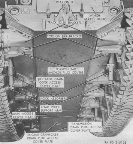
The underside of the hull is labeled here. Note the space between the fifth and rear torsion bar brackets: the rear road wheel used a leading arm, while the rest used trailing arms. (Picture from TM 9-7420 Operation and Organizational Maintenance Cargo Tractor M8E2.)
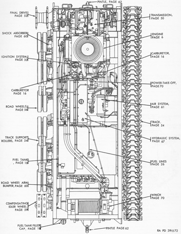
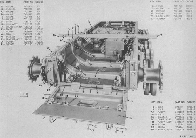
The spatial relationships between major components is discernible in this cross-sectional plan view. (Picture from TM 9-2430-200-20P Organizational Maintenance Repair Parts and Special Tools List for Tractor, Full Tracked, High Speed: M8A1 (2430-740-5800) and Tractor, Full Tracked, High Speed: M8A2 (2430-563-7250).)
The base hull is seen here with the engine and transmission removed and the front engine access door open. (Picture from ORD 9 SNL G-252 List of All Service Parts of Tractor, Full Tracked, High Speed: M8A1.)
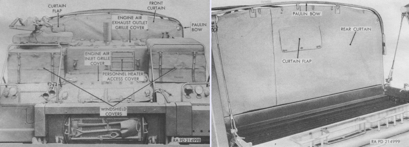
When the tractor was not in use, covers could be installed over the drivers' windshields and engine air grilles. In addition, front and rear curtains could be attached to the front and rear paulin bows. (Picture from TM 9-7420 Operation and Organizational Maintenance Cargo Tractor M8E2.)
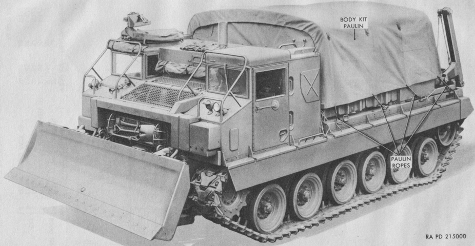
The body kit was also provided with a paulin that covered it entirely. (Picture from TM 9-7420 Operation and Organizational Maintenance Cargo Tractor M8E2.)
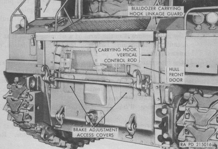
A closer look is given at the front of the tractor with the moldboard and components removed. The carrying hooks were manually operated from the driver's compartment to secure the moldboard for travel. (Picture from TM 9-7420 Operation and Organizational Maintenance Cargo Tractor M8E2.)
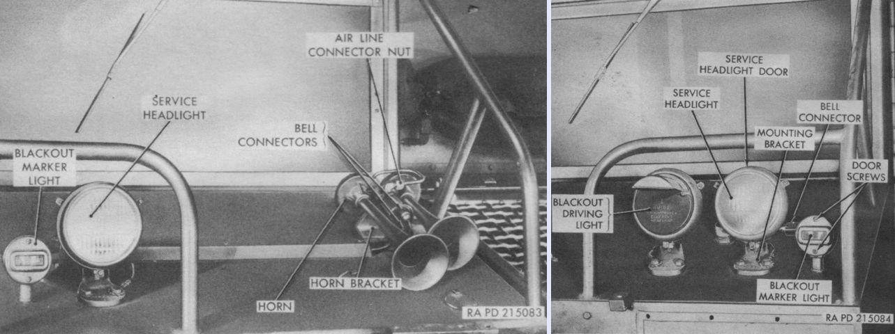
The left and right headlight groups are on the left and right above, respectively. The horn was an electrically-operated air diaphragm type. (Picture from TM 9-7420 Operation and Organizational Maintenance Cargo Tractor M8E2.)
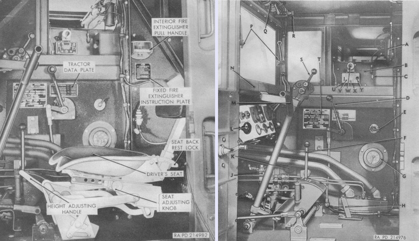
Views of the driver's compartment show his seat installed on the left and removed for clarity on the right. The legend for the right image is: A. Personnel heater fuel pump. B. Personnel heater. C. Heat outlet shutoff knob. D. Bulldozer control valve lever. E. Electric brake controller handle. F. Transmission range control lever. G. Tachometer. H. Main fuel shutoff valve lever. J. Primer pump and personnel heater fuel filter. K. Heat outlet. L. Engine primer pump handle. M. Steering control lever. N. Defroster air duct. P. Windshield adjustment knobs. Q. Windshield wiper motor. R. Windshield wiper control knob. S. Bulldozer carrying hook control lever. T. Tractor nameplate. U. Heater switch. V. Personnel heater instruction plate. W. Heater thermostat knob. X. Heater circuit breaker reset button. Y. Heater safety valve reset switch lever. (Picture from TM 9-7420 Operation and Organizational Maintenance Cargo Tractor M8E2.)
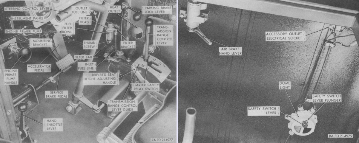
Controls at the bottom and on the ceiling of the driver's position are labeled at the left and right, respectively. Trailer brakes were typically operated along with the tractor brakes with the service brake pedal, but the driver could also engage trailer air brakes with the hand lever on the ceiling, though this was not an effective way of also braking the tractor. (Picture from TM 9-7420 Operation and Organizational Maintenance Cargo Tractor M8E2.)
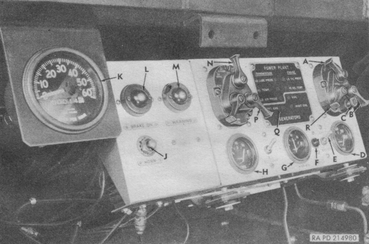
The driver's instrument panel is labeled. A. Engine magneto switch lever. B. Engine starter switch lever. C. Fuel cutoff switch button. D. Engine oil pressure gage. E. Master switch. F. Master switch warning light. G. Hydraulic oil gage. H. Fuel gage. J. Horn switch button. K. Speedometer and odometer. L. Parking brake on warning light. M. Master warning light. N. Main light switch lever. P. Main light switch safety lever. Q. Warning light panel. R. Magneto booster switch lever. (Picture from TM 9-7420 Operation and Organizational Maintenance Cargo Tractor M8E2.)
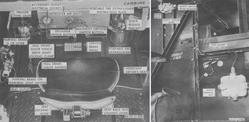
Two views of the assistant driver's compartment are provided here. The service brake pedals for both drivers were connected by a cross shaft, but otherwise the assistant driver could not control the tractor's motion. (Picture from TM 9-7420 Operation and Organizational Maintenance Cargo Tractor M8E2.)
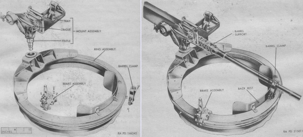
The 36" (91cm) ring mount M68 above the assistant driver is shown partially exploded and with the machine gun stowed in its clamp. The brake permitted the ring assembly to be locked at any desired position, and could be adjusted in tension from full on to full off. (Picture from TM 9-7420 Operation and Organizational Maintenance Cargo Tractor M8E2.)
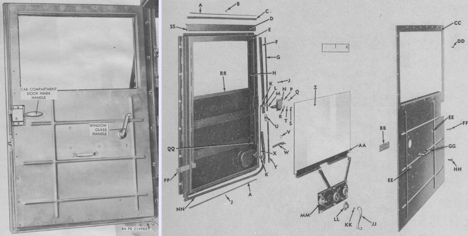
As shown in these assembled and exploded views of a crew door, the drivers were provided with rolling windows, a decently luxurious feature for a tracked military vehicle. (Picture from TM 9-7420 Operation and Organizational Maintenance Cargo Tractor M8E2 and ORD 9 SNL G-252 List of All Service Parts of Tractor, Full Tracked, High Speed: M8A1.)
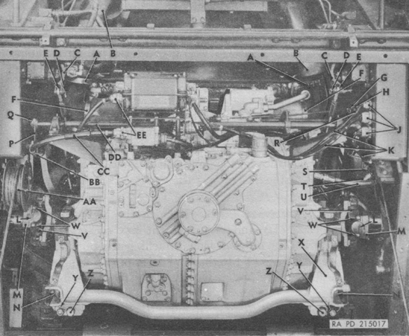
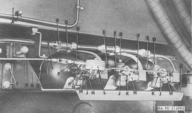
The power plant is shown installed with disconnect points labeled. A. Exhaust elbow upper clamp. B. Upper exhaust tube. C. Brake cam levers. D. Quick disconnect pin. E. Brake linkage rod. F. Exhaust elbow lower clamp. G. Quick disconnect pin. H. Throttle linkage yoke. J. Quick disconnects. K. Electrical harnesses. L. Universal joint locking wire. M. Final drive pinion flange. N. Power plant roller. P. Throttle control cross shaft linkage. Q. Cap screw. R. Accelerator shaft lever. S. Quick disconnect. T. Engine primer fuel line. U. Main fuel line. V. Universal joint. W. Hex socket-head cap screws. X. Power plant rails. Y. Power plant rail jack screw locking wire. Z. Power plant rail jack screw. AA. Hull front door winch cable drum. BB. Harness clip. CC. Generator regulator and starter relay electrical harness. DD. Throttle cross shaft. EE. Quick disconnects. (Picture from TM 9-7420 Operation and Organizational Maintenance Cargo Tractor M8E2.)
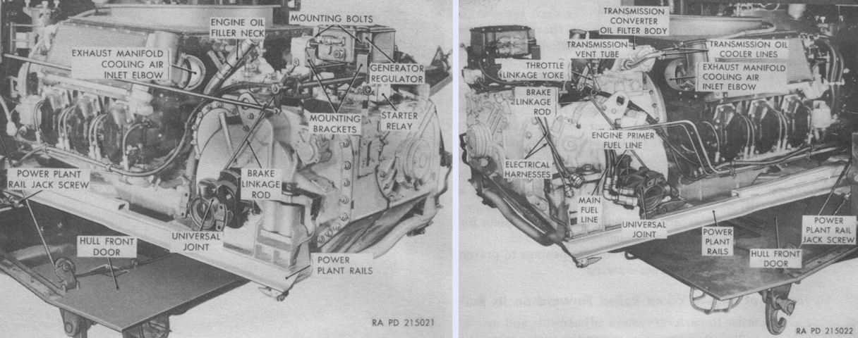
The power plant could be slid out from its compartment by rollers and rails. If necessary, it could be operated while rolled forward by using quick disconnect extension kits to provide fuel and electricity to the engine. (Picture from TM 9-7420 Operation and Organizational Maintenance Cargo Tractor M8E2.)
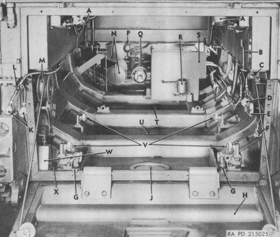
The power plant has been removed, revealing the empty engine compartment. A. Upper exhaust tube. B. Accelerator shaft lever. C. Quick disconnect (primer fuel line). D. Quick disconnect (electrical harness). E. Final drive pinion flange. F. Speedometer drive adapter. G. Power plant rail jackscrew. H. Hull front door. J. Transmission oil drain access cover plate. K. Quick disconnects. L. Generator regulator and starter relay electrical harness. M. Hull front door winch cable drum. N. Air storage tanks. P. Fixed fire extinguisher discharge nozzle. Q. Hydraulic pump. R. Hydraulic oil filter. S. Hydraulic oil reservoir tank. T. Hull access cover. U. Engine oil drain access cover plate. V. Power plant rollers W. Hull drain valve bracket. X. Hull drain valve. (Picture from TM 9-7420 Operation and Organizational Maintenance Cargo Tractor M8E2.)
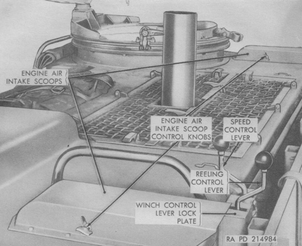
An engine air intake scoop was located on each side of the roof, and these could be directed via control knobs to either draw air from outside the cab during normal operation or from within the cab during very dusty conditions. If the outside temperature was below 40°F (4°C), the scoops were to draw air from outside the cab, otherwise air heated by the personnel heater would be siphoned off into the engine. (Picture from TM 9-7420 Operation and Organizational Maintenance Cargo Tractor M8E2.)
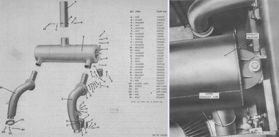
Unlike the M41 tank, which used an exhaust muffler on each rear fender, the M8A1 featured a single muffler that routed engine exhaust through the roof between the drivers. An exploded view is on the left, and the muffler and exhaust are installed on the right. (Picture from ORD 9 SNL G-252 List of All Service Parts of Tractor, Full Tracked, High Speed: M8A1 and TM 9-7420 Operation and Organizational Maintenance Cargo Tractor M8E2.)
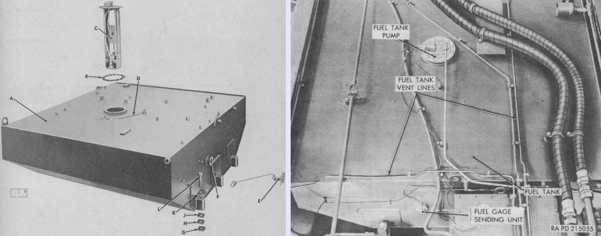
A single welded steel fuel tank was installed behind the engine, shown partially exploded on the left and installed in the tractor on the right. Early tractors used a fuel tank filler cap that had a combination vent and check valve that prevented fuel loss when the tractor was at extreme angles or overturned. Later models had a leakproof filler cap and, as shown here, the fuel tank was vented through two vent lines that extended to the cab rear wall. The legend for the left image is: A. Tank. B. Gasket. C. Pump, assy. D. Cable, assy. E. Unit. F. Gasket. G. Shim. H. Shim. J. Shim. K. Washer. L. Bolt. (Picture from ORD 9 SNL G-252 List of All Service Parts of Tractor, Full Tracked, High Speed: M8A1 and TM 9-7420 Operation and Organizational Maintenance Cargo Tractor M8E2.)
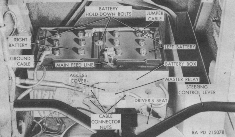
Two 12-volt, six-cell, lead-acid batteries, each rated 100 ampere hours for 20 hours at 80°F (27°C), were connected in series to obtain the 24 volts required for the electrical system. (Picture from TM 9-7420 Operation and Organizational Maintenance Cargo Tractor M8E2.)
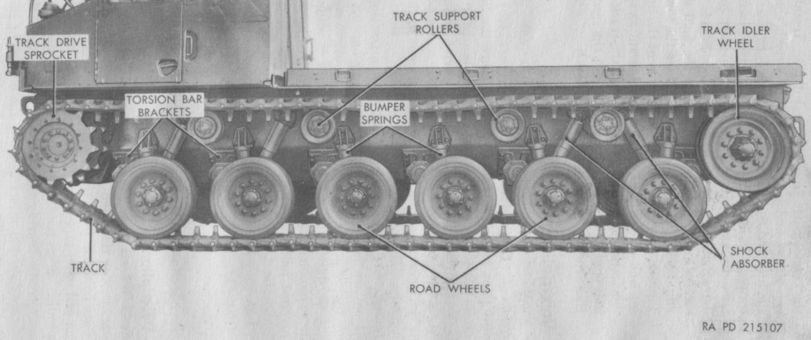
Suspension nomenclature is given in this image. (Picture from TM 9-7420 Operation and Organizational Maintenance Cargo Tractor M8E2.)
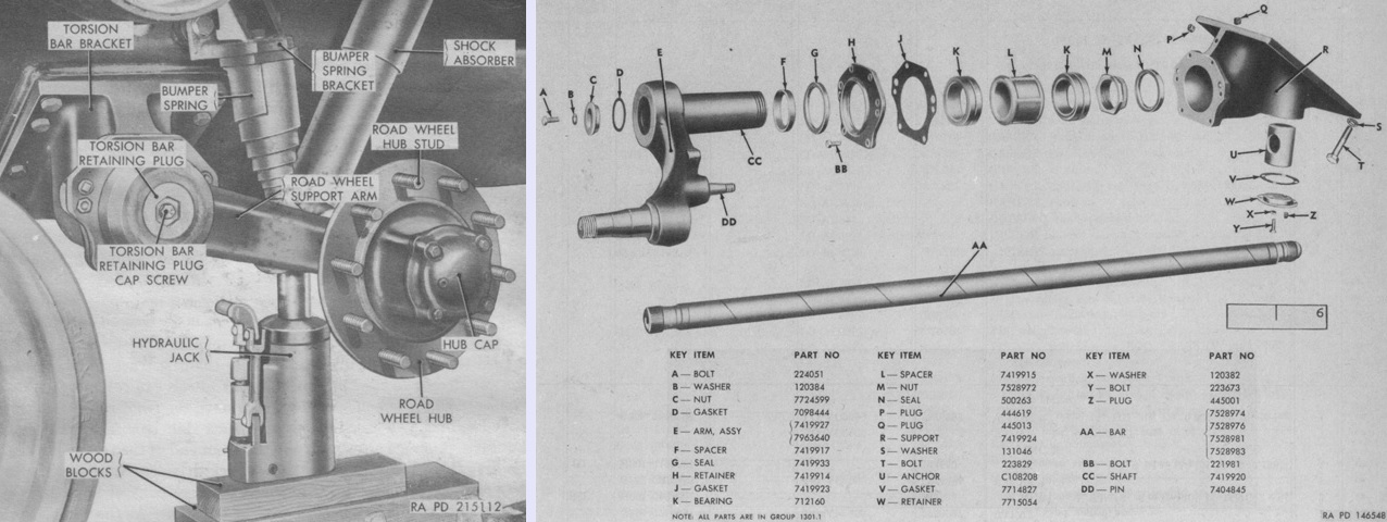
On the left, a road wheel has been removed, revealing more details of the suspension components. On the right is an exploded view of a torsion bar and road wheel arm and support. (Picture from TM 9-7420 Operation and Organizational Maintenance Cargo Tractor M8E2 and ORD 9 SNL G-252 List of All Service Parts of Tractor, Full Tracked, High Speed: M8A1.)
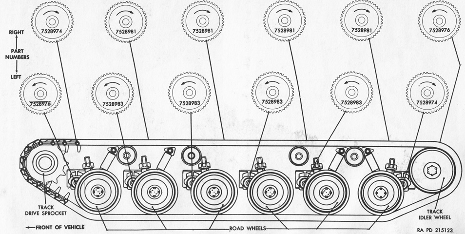
The torsion bars were designed to rotate in a single direction, so their installation depended on which side of the vehicle they were to be used. The front and rear torsion bars were different part numbers since those road wheels could encounter greater forces than the intermediate wheels. Note the rear torsion bars used the part numbers for the opposite side front wheels: since the rear wheels used leading arms instead of trailing arms, those bars rotated in the opposite direction. (Picture from TM 9-7420 Operation and Organizational Maintenance Cargo Tractor M8E2.)
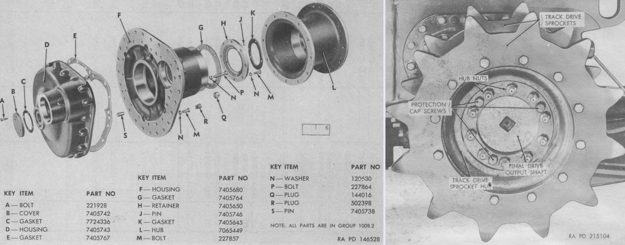
An exploded diagram of a final drive housing is shown on the left, and a track drive sprocket is on the right. After removing the ten self-locking hub nuts and three protective cap screws from the tapped jackscrew holes in the sprockets, three jackscrews were inserted into the tapped jackscrew holes and turned in to push the sprocket hub free. The twelve bolts and nuts securing the sprocket rings were torqued to 100-105 lb-ft each, and the ten self-locking hub nuts were torqued to 280-300 lb-ft. The jackscrew holes were not found on the M41 tank. (Picture from ORD 9 SNL G-252 List of All Service Parts of Tractor, Full Tracked, High Speed: M8A1 and TM 9-7420 Operation and Organizational Maintenance Cargo Tractor M8E2.)
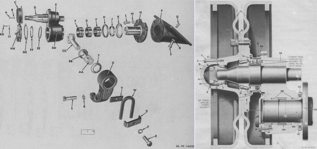
The rear idler wheel was mounted on the outer end of a spindle on the track idler pivot arm. The track idler pivot arm itself was mounted on a spindle of the track idler bracket, which was in turn bolted to the hull. This allowed movement of the wheel to increase or decrease track tension. Exploded and sectionalized views of the idler wheel mount are on the left and right, respectively. The legend for the left image is: A. Screw. B. Washer. C. Shedder. D. Spindle. E. Arm. F. Bushing. G. Spacer. H. Seal. J. Spacer. K. Guard. L. Bolt. M. Washer. N. Spindle. P. Support. Q. Pin. R. Washer. S. Bolt. T. Seat. U. Arm. V. Plate. W. Yoke. X Plate. Y. Washer. Z. Bolt. AA. Plug. BB. Nut. CC. Bolt. DD. Fitting. EE. Washer. FF. Ring. GG. Gasket. HH. Cover. JJ. Washer. KK. Screw.
The legend for the right image is: A. Lockwasher. B. Cap screw. C. Lock ring. D. Cover. E. Track idler wheel hub. F. Seal guard. G. Setscrew. H. Inner bearing. J. Outer bearing. K. Oil plug. L. Bearing adjusting nut. M. Ring. N. Static spring. P. Hub retaining nut. Q. Hub cap. R. Nut lock. S. Cap screw. T. Lockwasher. U. Gasket. V. O-ring. W. Oil seal cartridge. X. Stud nut. Y. Track idler wheels. Z. Cap screw. AA. Lockwasher. BB. Track idler pivot arm and spindle. CC. Dirt shield. DD. Bushings. EE. Spindle. FF. Oil seal. GG. Spacer. HH. Sleeve. JJ. Gasket. KK. Spacer ring. (Picture from ORD 9 SNL G-252 List of All Service Parts of Tractor, Full Tracked, High Speed: M8A1 and TM 9-7420 Operation and Organizational Maintenance Cargo Tractor M8E2.)
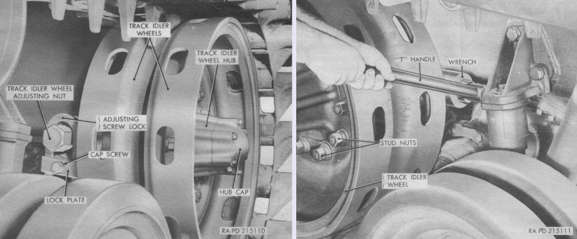
An adjusting screw was installed on the inner end of the track idler pivot arm spindle. After loosening the cap screw in the screw lock plate, the lock plate could be removed and the adjusting nut rotated counterclockwise to tighten and clockwise to loosen the track. (Picture from TM 9-7420 Operation and Organizational Maintenance Cargo Tractor M8E2.)
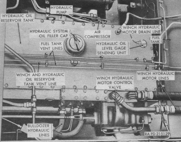
The 80-gallon (300L) reservoir tank for the hydraulic system was mounted immediately behind the engine, and the pump on the right wall of the reservoir tank was driven directly by the engine through the power take-off. This system provided pressure for the winch, and also for the bulldozer and generator hoist if the tractor was so equipped. (Picture from TM 9-7420 Operation and Organizational Maintenance Cargo Tractor M8E2.)
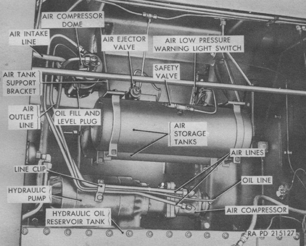
An air compressor was attached to the rear of the hydraulic pump and driven by the pump via a splined coupling connecting the pump and compressor shafts. The compressor maintained a pressure of 100-103psi (7.03-7.24kg/cm²) in the system to supply air for the horn, windshield wipers, service brake boosters, and trailer air brakes. (Picture from TM 9-7420 Operation and Organizational Maintenance Cargo Tractor M8E2.)
A Gar Wood model 5M 728 hydraulic worm gear winch was mounted at the rear of the hull for towing and loading operations. (Picture from TM 9-7420 Operation and Organizational Maintenance Cargo Tractor M8E2.)
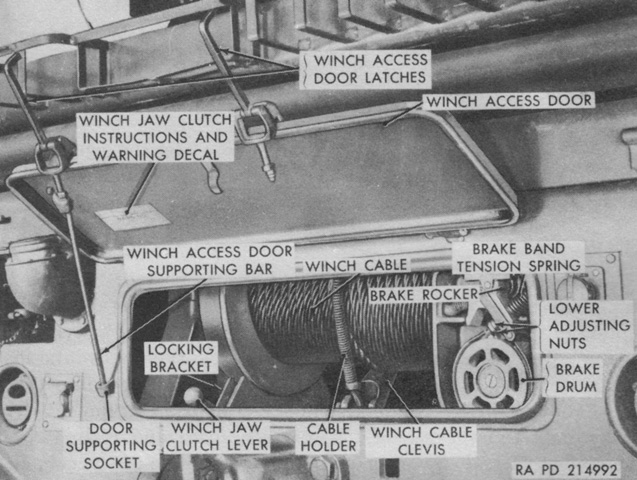
The winch had a 45,000lb (20,400kg) capacity and was supplied with 300' (91m) of ¾" (1.9cm) cable. A drum drag brake was applied as the winch jaw clutch was disengaged in order to keep the drum from spinning. A second automatic band brake was spring-applied when the input power to the winch was stopped, so that the worm shaft did not back up. (Picture from TM 9-7420 Operation and Organizational Maintenance Cargo Tractor M8E2.)
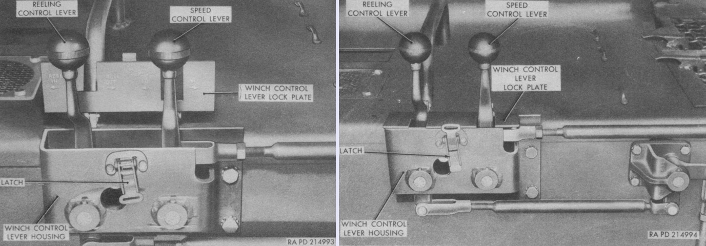
The winch had a two-speed reversible drum controlled by levers mounted at the upper left rear corner of the cab. The lever housing had a lock plate to prevent unintended movement of the levers when the winch was not in use. The speed control lever was used to switch between high and low speeds. High speed was used when unreeling the cable or when towing relatively light loads, while the low speed range was used when moving heavy loads or when load control was essential. The reeling control lever controlled the direction of the winch drum in order to reel cable in or out. Reeling in speed could be further controlled with engine rpm. (Picture from TM 9-7420 Operation and Organizational Maintenance Cargo Tractor M8E2.)
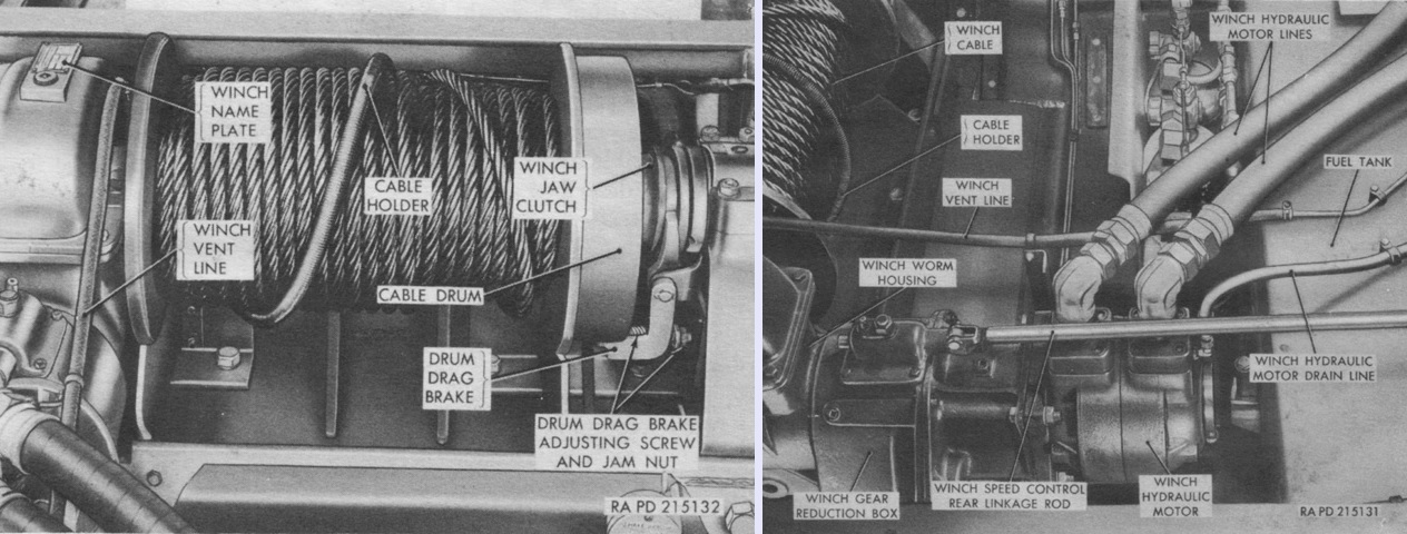
The winch is seen from behind on the left with the cargo platform removed, and the winch hydraulic motor is on the right, also with the cargo platform removed. The winch used a vane-type hydraulic motor driven by the tractor's hydraulic pump, which was in turn driven by the engine power take-off. (Picture from TM 9-7420 Operation and Organizational Maintenance Cargo Tractor M8E2.)
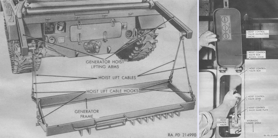
The hoist in the tractor body kit T48 could be used to lift or lower the generating set M18 or a cargo pallet. The hoist control valve lever shown on the right was pulled toward the outside of the tractor to lower the hoist and pushed inward to raise the hoist. Releasing the lever would return it to its hold position. The hoist took 51 seconds to lift a load and 21 seconds to lower with the engine at 1,500-2,100rpm. (Picture from TM 9-7420 Operation and Organizational Maintenance Cargo Tractor M8E2.)
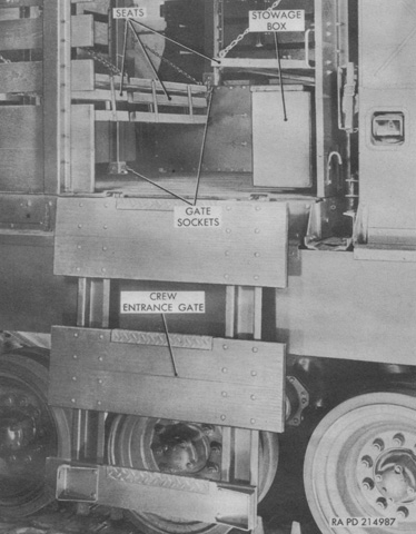
The Skysweeper gun crew could mount the vehicle by use of a gate attached to the cargo platform. Three hinged seats accommodated the gun crew for travel. (Picture from TM 9-7420 Operation and Organizational Maintenance Cargo Tractor M8E2.)
The fixed fire extinguisher system used three 10lb (4.5kg) CO2 bottles mounted behind the fuel tank, seen here with the cargo platform removed. They were routed to three discharge nozzles: one above the fuel tank, one at the rear of the engine, and the third above the transmission. All cylinders discharged together when the outside or inside handles were pulled. A portable CO2 extinguisher was also carried in the assistant driver's compartment. A. Fuel tank. B. Discharge link connector nut. C. Discharge manifold assembly. D. Red safety cap seal. E. Fire extinguisher cylinder. F. Cylinder connecting pressure lines. G. Winch hydraulic motor. H. Manifold elbow connector head. J. Cylinder connector head. K. Release assembly. L. Control head. M. Control head connector. N. Inner connector release. P. Control cable tubing. Q. Cylinder clamp. R. Mounting bracket. S. Cap screws, lockwashers, and plain washers. (Picture from TM 9-7420 Operation and Organizational Maintenance Cargo Tractor M8E2.)
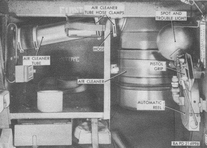
A spot and trouble light was stowed on the outer wall of the driver's compartment just behind the door. The cord was wound on an automatic reel, and a pistol grip was attached to the light. Enough cord was provided so that the light could reach any location around the tractor, and the pistol grip contained a thumb lock for keeping the light switch in the on position. (Picture from TM 9-7420 Operation and Organizational Maintenance Cargo Tractor M8E2.)
