
38-ton High-speed Tractor M6.
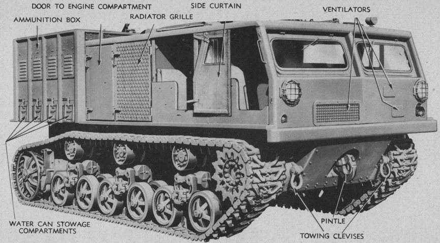
The tractor is shown here from the left front. The engine compartment is between the crew compartment and cargo box, and towing pintles were available at the front and rear. (Picture from TM 9-788/TO 19-75AJ-66 38-ton High Speed Tractor M6.)
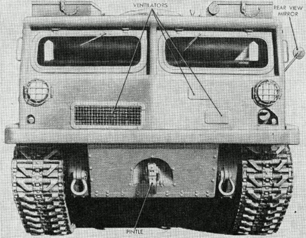
In addition to the ventilators in the cab front, the windshields could also be opened for air circulation. (Picture from TM 9-788/TO 19-75AJ-66 38-ton High Speed Tractor M6.)

The large roof provided ample stowage space, and pioneer tools, spare tracks, and toolboxes were all secured there. The interior of the ammunition and cargo box is visible from this angle with the canvas cover removed. (Picture from TM 9-788/TO 19-75AJ-66 38-ton High Speed Tractor M6.)

The underside of the hull is labeled. A. Final drive drain plugs. B. Transmission and differential drain plug access plate. C. Torque-converter maintenance and inspection plates. D. Hull drain plugs. E. Engine maintenance plate. F. Engine oil drain plug access plates. G. Fuel filter drain plug access plates. H. Hull clean-out access plates. J. Fuel tank drain plug access plate. (Picture from TM 9-788/TO 19-75AJ-66 38-ton High Speed Tractor M6.)

The winch was mounted at the rear of the tractor under the ammunition and cargo box. (Picture from TM 9-788/TO 19-75AJ-66 38-ton High Speed Tractor M6.)
Seen from the right front, the label for the ammunition box lower compartment is different in this image. (Picture from TM 9-1788 Ordnance Maintenance--Tractor, High-speed, 38-ton, M6--Power Train, Suspension, Body, and Equipment.)
The cargo and ammunition box is open and uncovered. Shell racks and hold-down bars were present in the outer compartments to secure artillery ammunition. (Picture from TM 9-788/TO 19-75AJ-66 38-ton High Speed Tractor M6.)
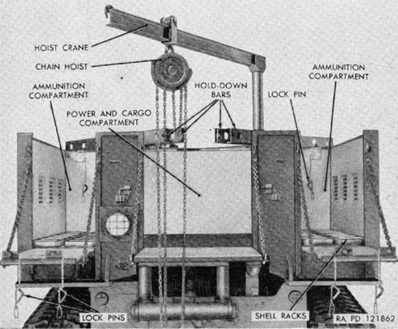
A swinging crane with a trolley hoist could be installed in sockets in the corner of the center compartment of the ammunition and cargo box. When not needed, it could be stowed in the cargo compartment. (Picture from TM 9-788/TO 19-75AJ-66 38-ton High Speed Tractor M6.)
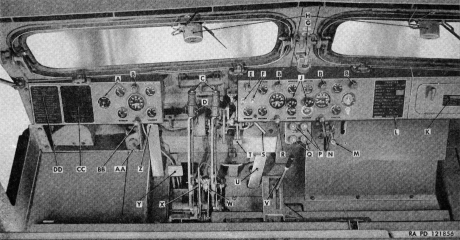
An overview of the driver's position is given here. A. Electric brake load control. B. Panel lights. C. Steering lever locks. D. Steering levers. E. Main light switch. F. Starter button switches. G. Compass. H. Windshield wipers. J. Fuel primer pumps. K. Vehicle data plate. L. Vehicle name plate. M. Throttle control lever. N. Windshield wiper switch. P. Engine shut-off control. Q. Choke control knobs. R. Panel light switch. S. Trailer air brake valve lever. T. Trailer brake pedal. U. Accelerator pedal. V. Gearshift lever. W. Power take-off range shifter lever. X. Power take-off shifter lever. Y. Clutch pedal. Z. Dimmer switch. AA. Siren switch. BB. Blackout driving light switch. CC. Gearshift lever diagram plate. DD. Vehicle lubrication instruction plate. (Picture from TM 9-788/TO 19-75AJ-66 38-ton High Speed Tractor M6.)

The driver's instrument panels are detailed in this image. A. Torque-converter oil pressure gages. B. Engine tachometers. C. Engine oil pressure gages. D. Ammeter. E. Speedometer. F. Transmission oil pressure gage. G. Hour meter. H. Transmission oil temperature gage. J. Air pressure gage. K. Torque-converter oil temperature gages. L. Engine coolant temperature gages. M. Low air pressure indicator light. N. Fuel level gage. (Picture from TM 9-788/TO 19-75AJ-66 38-ton High Speed Tractor M6.)
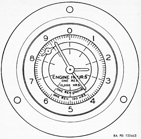
The hour meter had four hands. The small hand in the upper left was used to indicate when the hour meter was operating, and would rotate as soon as the tractor's right engine was started. The three hands in the center were used to record the time the engines had operated. (Picture from TM 9-788/TO 19-75AJ-66 38-ton High Speed Tractor M6.)
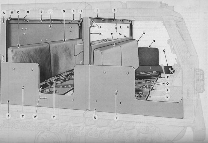
The front and rear seats are labeled in this image, although only the driver's seat cushion is present. The seat cushions were padded canvas zipper bags, while the seat backs were leather covered. A. Post. B. Bolt/nut/washer. C. Cushion. D. Angle. E. Bolt/nut/washer/washer. F. Back. G. Cushion. H. Bolt/nut/washer/washer. I. Angle. J. Bolt/nut/washer. K. Post. L. Post. M. Back. N. Cushion. O. Plate. P. Bag. Q. Belt, assembly. R. Frame. S. Frame. T. Bolt/washer. U. Plate. V. Bolt/nut/washer/washer/washer. W. Channel. X. Plate. (Picture from ORD 9 SNL G-184 List of All Service Parts for Tractor, High Speed, 38-ton, M6 (Allis-Chalmers).)
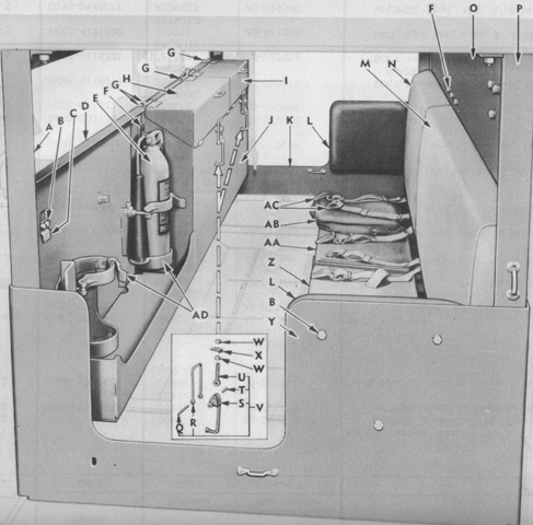
An overview of the rear seat is provided here. Again, only the far seat cushion is present. A. Post. B. Bolt/washer. C. Clip. D. Back. E. Extinguisher, assembly. F. Bolt/washer. G. Bolt/nut/washer/washer. H. Lid. I. Lid. J. Box. K. Plate. L. Cushion. M. Cushion. N. Cushion. O. Back. P. Post. Q. Pin. R. Clevis. S. Lever. T. Pin. U. Eye-bolt. V. Latch, assembly. W. Nut. X. Lock. Y. Plate. Z. Frame. AA. Frame. AB. Bag. AC. Belt, assembly. AD. Bracket, assembly. (Picture from ORD 9 SNL G-184 List of All Service Parts for Tractor, High Speed, 38-ton, M6 (Allis-Chalmers).)
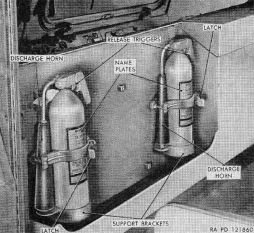
As shown above, two portable 4lb (2kg) CO2 fire extinguishers were mounted on a bracket fastened to the back of the driver's seat and accessible from the rear passenger compartment. (Picture from TM 9-788/TO 19-75AJ-66 38-ton High Speed Tractor M6.)
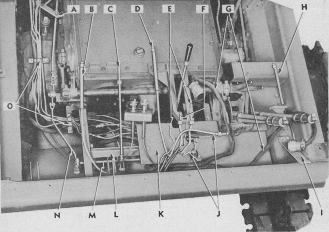
The front of the tractor is detailed with the cab removed. A. Throttle rod support. B. Tachometer cable. C. Hand throttle rod. D. Speedometer cable. E. Primer pump fuel discharge pipes. F. Primer pump fuel suction pipes. G. Wiring harnesses. H. Tachometer cable. I. Foot rest. J. Air pipes. K. Left floor plate. L. Throttle cross shaft and floor plate support. M. Throttle cross shaft. N. Front throttle rod. O. Pipe clips. (Picture from TM 9-1788 Ordnance Maintenance--Tractor, High-speed, 38-ton, M6--Power Train, Suspension, Body, and Equipment.)

Two Waukesha 145GZ engines were used to power the M6. The 18-ton high-speed tractor M4 used the same engine, but only a single example. The flywheels of the engines were mounted in a common clutch housing, and each engine had its own electric starter, water and fuel pump, carburetors, oil cooler, cooling system, governor, and injection system. The engines were operated by a single clutch pedal and by common throttle controls. The generator was found on the right engine, and the air compressor for trailer air brakes was on the left engine. (Picture from TM 9-788/TO 19-75AJ-66 38-ton High Speed Tractor M6.)
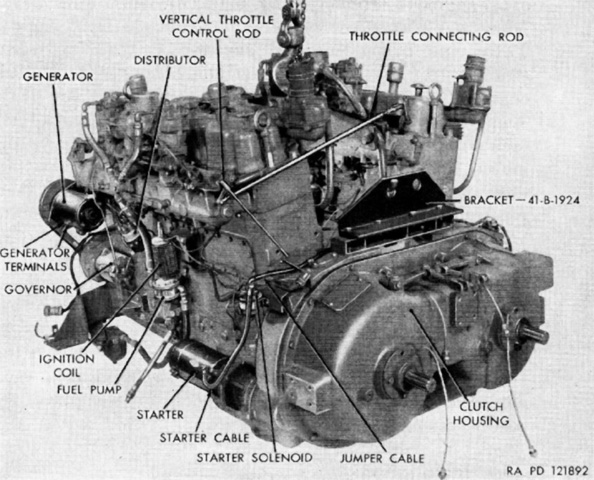
From the right front, the common clutch housing and generator can be seen. The engines' firing order was 1-5-3-6-2-4, and 6 gallons (23L) of oil were required to fill the crankcase and oil filter of each engine. (Picture from TM 9-788/TO 19-75AJ-66 38-ton High Speed Tractor M6.)

The engines are shown here being separated from each other. (Picture from TM 9-788/TO 19-75AJ-66 38-ton High Speed Tractor M6.)
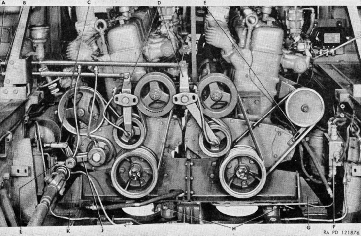
The engines are seen from the rear installed with the fan, air compressor, and generator drive belt arrangement highlighted. A. Lock nuts. B. Belt adjusting nuts. C. Air compressor belt adjusting link. D. Fan drive belt tightener. E. Generator belt adjusting link. F. Electrical junction box. G. Engine rear support. H. Fuel filters. J. Air compressor belt tightener. K. Engine rear support. L. Winch drive shaft bearing. (Picture from TM 9-788/TO 19-75AJ-66 38-ton High Speed Tractor M6.)
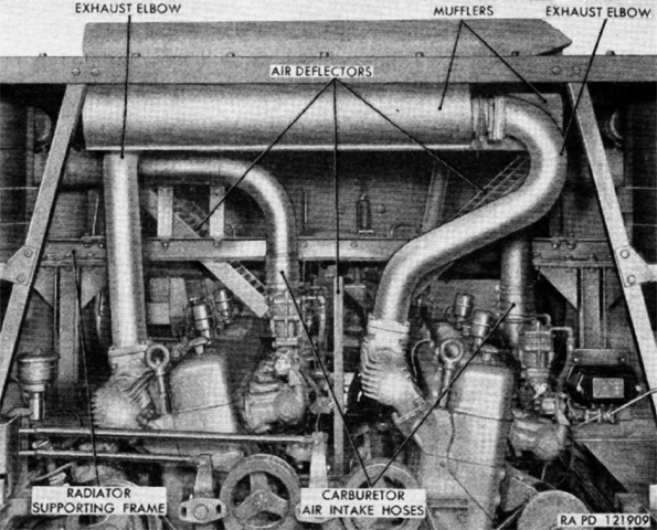
The exhaust manifolds and mufflers flowed upwards through the roof of the engine compartment. (Picture from TM 9-788/TO 19-75AJ-66 38-ton High Speed Tractor M6.)
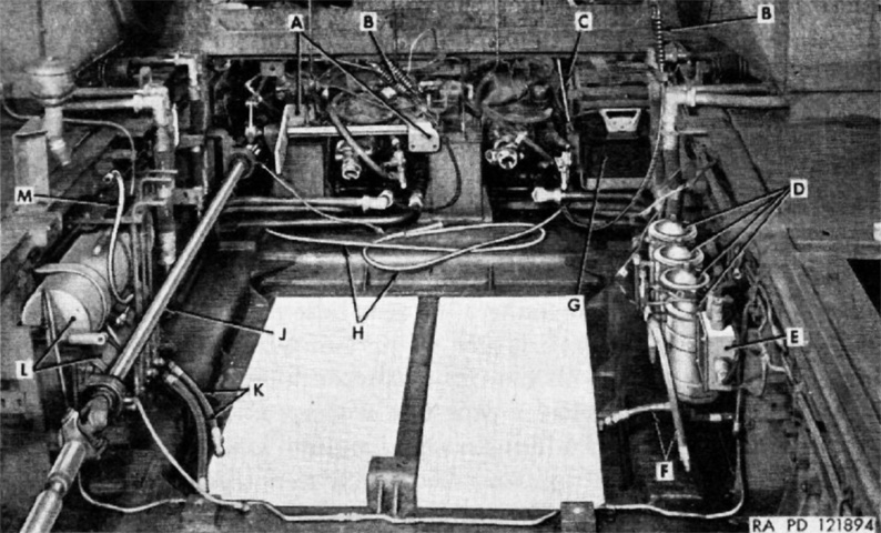
The engines have been removed from the engine compartment in this image. A. Clutch control shaft mounting brackets. B. Choke and engine shut-off cables. C. Throttle control rod. D. Oil filters. E. Electrical junction box. F. Oil hoses. G. Battery. H. Tachometer drive shafts. J. Winch drive shaft assy. K. Water drain hoses. L. Air reservoirs. M. Air compressor discharge pipe. (Picture from TM 9-788/TO 19-75AJ-66 38-ton High Speed Tractor M6.)
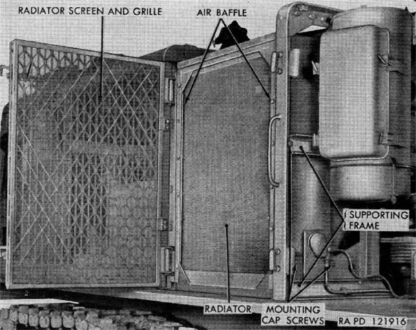
A radiator shell on each side of the engine compartment contained three radiators, the outer one for cooling the torque converter oil, the center was for engine coolant, and the inner radiator was for the transmission, differential, and power take-off case oil. A fan drew air through each set of radiators, dissipating heat build-up in the oil and coolant. One of the two engine air cleaners is visible on the right side of the image. An oil cup was at the bottom of the air cleaner, and the rectangular piece attached to the outside was the dirt receptacle. (Picture from TM 9-788/TO 19-75AJ-66 38-ton High Speed Tractor M6.)
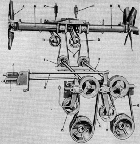
The arrangement of the cooling fans inboard of the radiators is diagrammed in this picture. A. Cooling fan blades. B. Housing. C. Hood grille fan belt adjusters. D. Belt tightener pulleys. E. Cooling fan belts. F. Fan drive shafts. G. Cooling fan drive belts. H. Drive belt adjuster rods. J. Left engine compartment fan drive adjusters. (Picture from TM 9-788/TO 19-75AJ-66 38-ton High Speed Tractor M6.)

The engine hood, air cleaners, and mufflers could be removed as a single unit once various fixtures had first been disconnected. (Picture from TM 9-788/TO 19-75AJ-66 38-ton High Speed Tractor M6.)
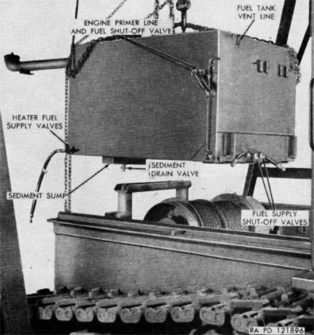
The fuel tank, seen here being removed, was installed at the bottom of the hull under the ammunition box. Two valves with hoses were provided that led to fittings on the hull side and rear that could be connected to heaters if necessary during cold weather. (Picture from TM 9-788/TO 19-75AJ-66 38-ton High Speed Tractor M6.)

Two 12-volt wet-cell storage batteries were connected in parallel in a support under the floor on the right side of the hull. The two positive terminals were connected to the starter of the right-side engine. (Picture from TM 9-788/TO 19-75AJ-66 38-ton High Speed Tractor M6.)
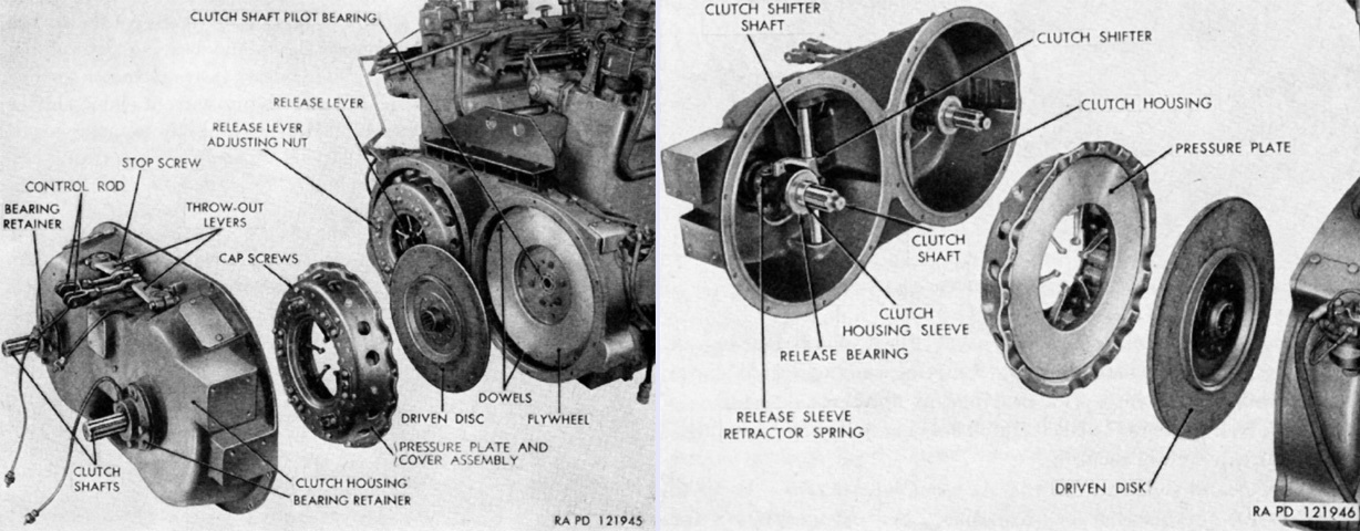
A single clutch housing supported the front of each engine and contained both of the spring-loaded, dry disk clutch assemblies. (Picture from TM 9-788/TO 19-75AJ-66 38-ton High Speed Tractor M6.)
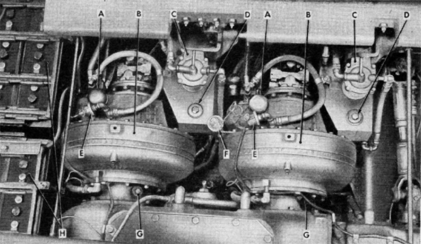
Two Twin-disk model T-10010 torque converters were mounted at the rear of the transmission. These were used to develop the required engine torque to start the pulling of heavy loads, smooth starting movement and acceleration, and prevent stalling or clutch slip under heavy loads since the engines could maintain their operating speed. A. Converter pump drive housing. B. Torque-converters. C. Converter oil filters. D. Oil reservoir fill plugs and level gage rods. E. Oil pressure gage sending units. F. Transmission oil pressure gage sending unit. G. Transmission breathers. H. Batteries. (Picture from TM 9-788/TO 19-75AJ-66 38-ton High Speed Tractor M6.)
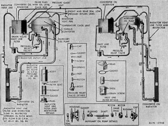
The torque converter oil circulatory system is diagrammed here. Each torque converter system contained 9½gal (36L) of oil. (Picture from TM 9-788/TO 19-75AJ-66 38-ton High Speed Tractor M6.)
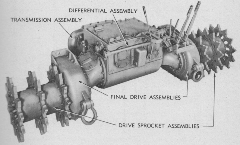
The assembled powertrain is seen from the front with the driver's controls installed; the entire assembly could be mounted as a single unit. Note that the drive sprocket assemblies unusually used three sprocket rings each. (Picture from TM 9-1788 Ordnance Maintenance--Tractor, High-speed, 38-ton, M6--Power Train, Suspension, Body, and Equipment.)
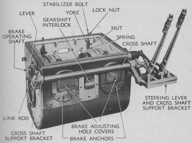
The interior of the transmission can be glimpsed with its covers removed. The transmission case held 22gal (83L) of oil, which also served the differential and power take-off assemblies. (Picture from TM 9-1788 Ordnance Maintenance--Tractor, High-speed, 38-ton, M6--Power Train, Suspension, Body, and Equipment.)
A cross-section of the transmission is sketched along with the gearshift lever positions. In addition to high ("H") range, low ("L") range, reverse ("R"), and neutral ("N"), an engine brake ("EB") position was available in order to hold the tractor to a slow speed while descending steep grades. (Picture from TM 9-1788 Ordnance Maintenance--Tractor, High-speed, 38-ton, M6--Power Train, Suspension, Body, and Equipment.)
The cover has been removed from the differential case, revealing the differential assembly and steering brakes. (Picture from TM 9-788/TO 19-75AJ-66 38-ton High Speed Tractor M6.)
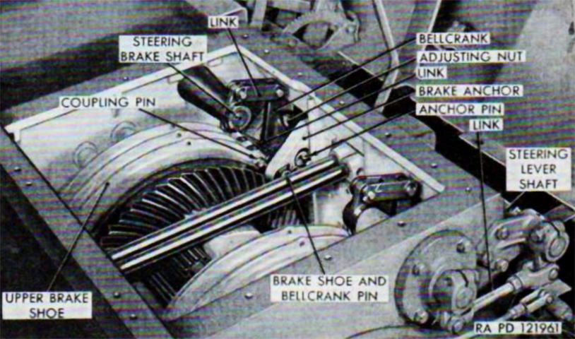
The differential case has been dismounted here, showing the steering brake shafts and linkages. (Picture from TM 9-1788 Ordnance Maintenance--Tractor, High-speed, 38-ton, M6--Power Train, Suspension, Body, and Equipment.)
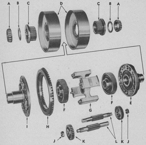
The differential gear assembly is labeled in this exploded diagram. A. Differential bearings. B. Thrust washers. C. Brake drum hubs. D. Brake drums. E. Right compensating case cover. F. Differential final drive shaft gear. G. Compensating case spider. H. Bevel gear. I. Left compensating case cover. J. Pinion shaft nuts. K. Differential outer pinions. L. Differential pinions and shafts. (Picture from TM 9-1788 Ordnance Maintenance--Tractor, High-speed, 38-ton, M6--Power Train, Suspension, Body, and Equipment.)
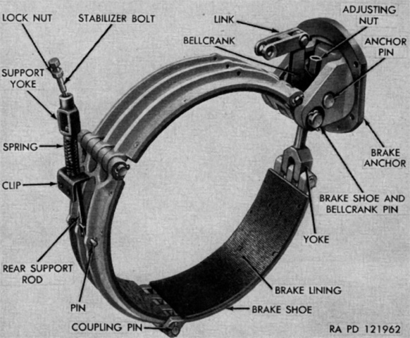
A steering brake assembly is seen removed from the differential. The steering levers contracted the brake shoes of their respective brakes around drums on the differential, which would set the differential's planetary gears in motion, slowing the selected drive sprocket and speeding the opposite drive sprocket, thereby turning the tractor. (Picture from TM 9-788/TO 19-75AJ-66 38-ton High Speed Tractor M6.)
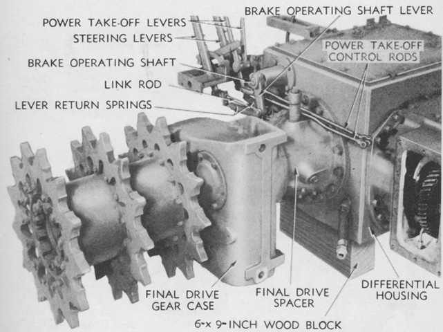
The final drives with their three sprocket rings are highlighted in this picture, with the powertrain dismounted and resting on wood blocks. Each final drive case held 6¼gal (23.7L) of oil. (Picture from TM 9-1788 Ordnance Maintenance--Tractor, High-speed, 38-ton, M6--Power Train, Suspension, Body, and Equipment.)
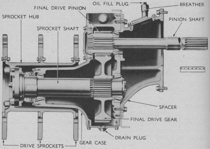
A cross-section of the final drive is drawn here. Note the orientation of the bolts securing the three sprocket rings. (Picture from TM 9-1788 Ordnance Maintenance--Tractor, High-speed, 38-ton, M6--Power Train, Suspension, Body, and Equipment.)

The track sprockets and hub are exploded in this image. The outer flange is scalloped to allow the center sprocket ring to pass, and the bolt orientation for the inner sprocket ring is opposite the outer two. The center sprocket used bolts that were 1⅝" (4.128cm) long, while the outer sprockets used 2" (5.1cm) long bolts. A. Bolt. B. Sprocket. C. Nut. D. Hub. E. Nut. F. Washer. G. Bolt. (Picture from ORD 9 SNL G-184 List of All Service Parts for Tractor, High Speed, 38-ton, M6 (Allis-Chalmers).)

The suspension is detailed in this picture along with the recommended track sag that indicated proper tension. The support rollers were mounted to the hull through an opening in the suspension bracket. (Picture from TM 9-788/TO 19-75AJ-66 38-ton High Speed Tractor M6.)
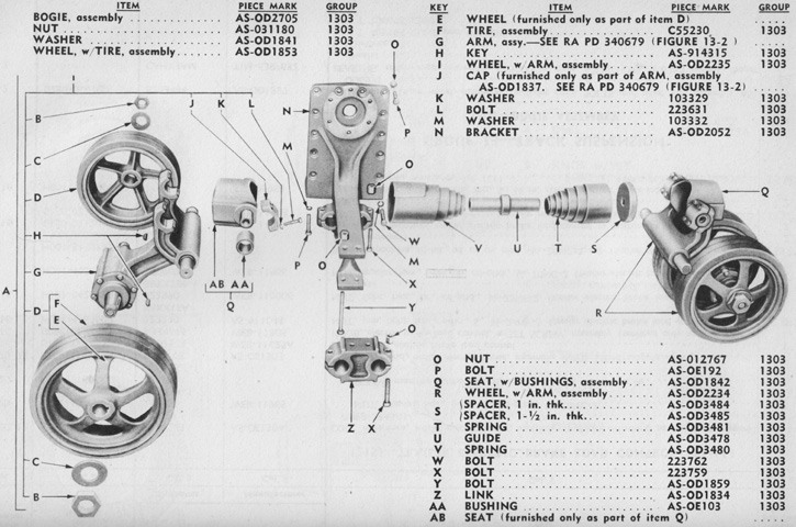
Parts of a suspension bogie are labeled in this image. The hole in the bogie bracket through which the support roller was mounted to the hull can be seen. (Picture from ORD 9 SNL G-184 List of All Service Parts for Tractor, High Speed, 38-ton, M6 (Allis-Chalmers).)

A cross-section of the trailing idler assembly is sketched here. The eccentric hub is ghosted behind the wheel. Volute springs mounted in the hull limited the upward motion of the idler arm, and rollers connected to the idler arm were present ahead of the wheel. (Picture from TM 9-788/TO 19-75AJ-66 38-ton High Speed Tractor M6.)
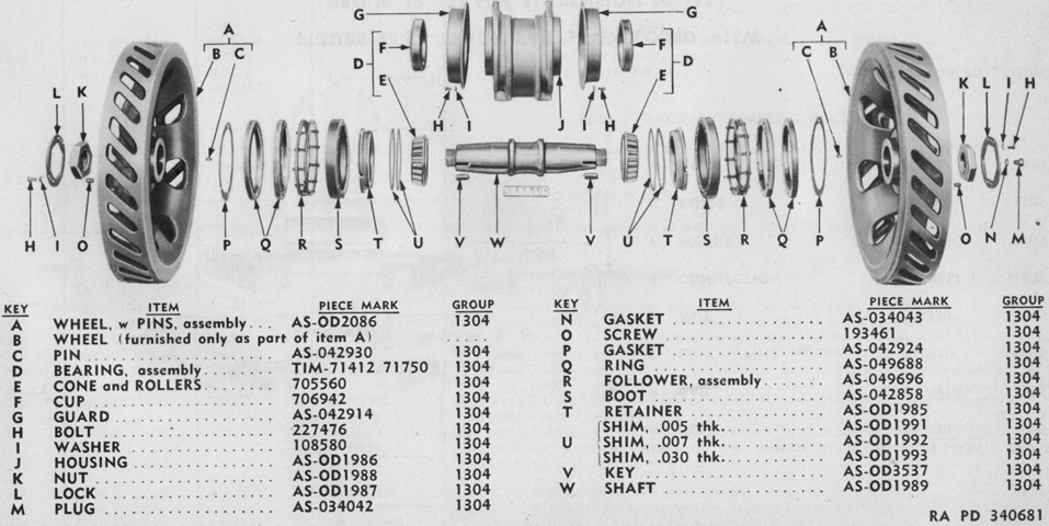
An exploded view of the idler wheel assembly is provided here, with the eccentric hub labeled as J. (Picture from ORD 9 SNL G-184 List of All Service Parts for Tractor, High Speed, 38-ton, M6 (Allis-Chalmers).)
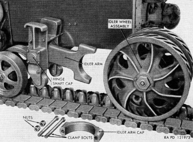
The idler wheel has been removed in this picture, with the idler arm cap and clamp bolts on the ground beside the track. (Picture from TM 9-788/TO 19-75AJ-66 38-ton High Speed Tractor M6.)

The idler wheel volute springs are seen with the fuel tank to the left. Downward motion of the idler arm was limited by the idler spring arm stop. (Picture from TM 9-788/TO 19-75AJ-66 38-ton High Speed Tractor M6.)
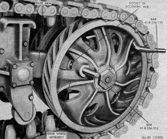
In order to adjust the track tension, the flange hole in the idler wheel first needed to be aligned with the socket in the eccentric idler hub. A special bar tool was then inserted into the socket through the flange hole, and a second type of bar tool was installed at the rear of the wheel and hooked between two track end connectors. The two clamp bolts at the rear of the idler arm were loosened, then the tractor was slowly moved forward to tighten the track or to the rear to loosen the track. (Picture from TM 9-788/TO 19-75AJ-66 38-ton High Speed Tractor M6.)
The power take-off was mounted on the transmission case and was driven by the high range pinion on the left transmission input shaft. It had two operating speeds and was reversible, so that the winch could wind or unwind cable from the drum. Its maximum speed was 350rpm at 2,100 engine rpm. (Picture from TM 9-788/TO 19-75AJ-66 38-ton High Speed Tractor M6.)

The interior of the power take-off is seen here. A. Worm shaft. B. Top cover. C. Worm gear housing. D. Coupling gear. E. Sliding gear. F. Washer. G. Output shaft. H. Screw lock. I. End washer. J. Driving gear. K. Sliding pinion. L. Driving gear shaft. M. Reverse gear. N. Cover. O. Cap screws. P. Screw lock. Q. End washer. R. Bearing. S. Washer. T. Low speed gear. U. Snap ring. V. Reverse shaft. W. Bevel gears. (Picture from TM 9-1788 Ordnance Maintenance--Tractor, High-speed, 38-ton, M6--Power Train, Suspension, Body, and Equipment.)

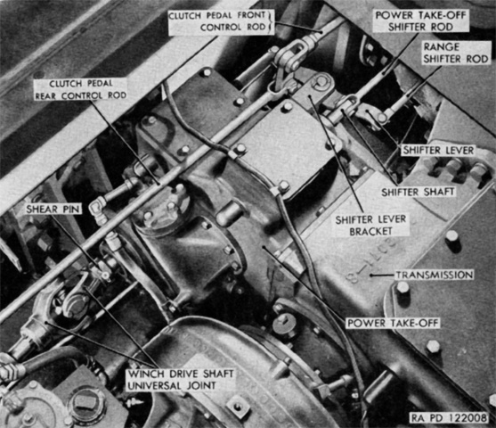
The winch was a standard heavy-duty military type, and was connected to the two-speed power take-off on the transmission case by drive shafts with universal joints. A control lever on the right side of the winch operated a sliding jaw clutch that enabled the worm and gear to drive the winch drum. An automatic brake on the winch worm shaft held the load when the engine master clutch was disengaged. The power take-off shifter lever in the driver's compartment was placed in the forward position to unwind cable and to the rear to wind cable, while its center position was neutral. The power take-off range shifter lever switched between the power take-off's high and low speed ranges; forward was high speed and rearward was low speed. The power take-off's low range was to be used only when the winch was used to assemble the 8" gun or 240mm howitzer; the high range was sufficient for all other winch work. (Picture from TM 9-788/TO 19-75AJ-66 38-ton High Speed Tractor M6.)
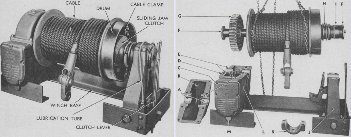
The winch is seen dismounted from the tractor on the left, and the drum shaft assembly is being removed from the gear case and end frame on the right. The legend for the right image is: A. Bushings. B. Gear case cover. C. Brake housing cover. D. Dowels. E. Gaskets. F. End washers. G. Worm gear. H. Clutch. I. Sleeve. J. End frame assembly. K. End frame cap. L. Gear case. M. Pivot bolt. (Picture from TM 9-1788 Ordnance Maintenance--Tractor, High-speed, 38-ton, M6--Power Train, Suspension, Body, and Equipment.)
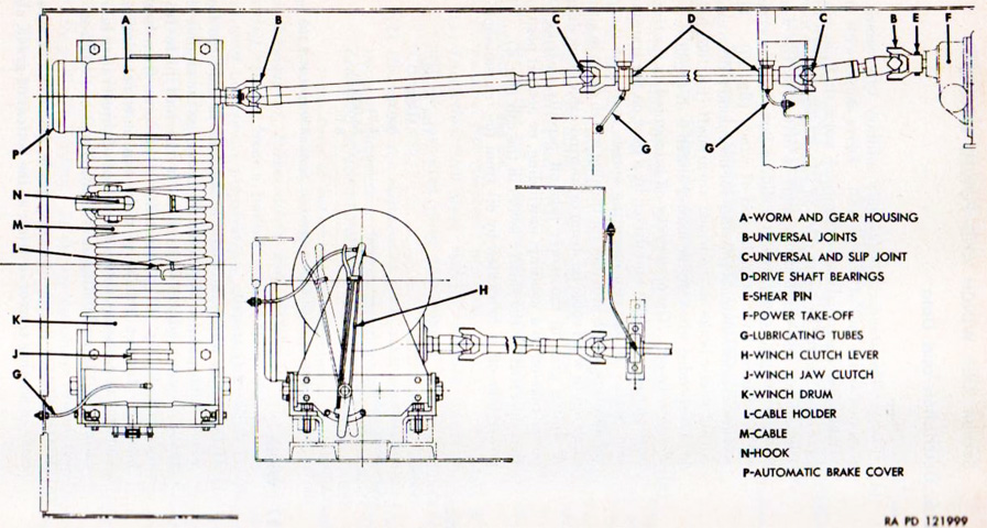
The winch and drive shaft assemblies are drawn in this diagram. (Picture from TM 9-788/TO 19-75AJ-66 38-ton High Speed Tractor M6.)
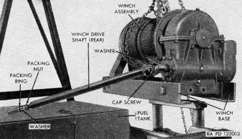
The winch and drive shaft assemblies are seen here in the process of being removed. The gear case is on the near side of the winch. (Picture from TM 9-788/TO 19-75AJ-66 38-ton High Speed Tractor M6.)
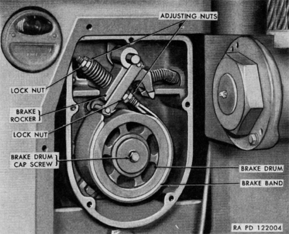
The winch brake could be accessed after removing the plate on the hull left rear and the cover plate on the brake housing. (Picture from TM 9-788/TO 19-75AJ-66 38-ton High Speed Tractor M6.)

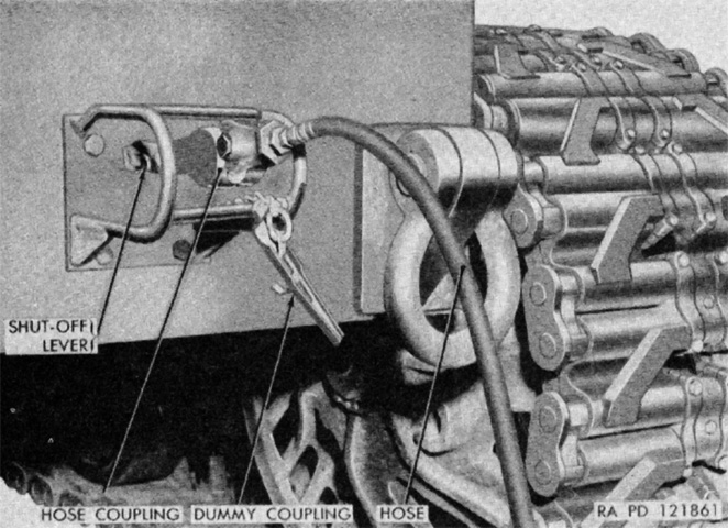
The air brake control system is the subject of this diagram. A 2-cylinder Bendix-Westinghouse Model No. 2-UE-71/4-VW compressor was mounted on a mat on the timing gear housing of the left engine. The compressor was lubricated with oil from the engine lubrication system, water cooled, and driven by a belt from a pulley on the engine crankshaft. The compressor could displace 7¼cfm (.205m³/min) at a rated speed of 1,250rpm at 1,475 engine rpm. The air storage reservoirs were 8x26" (20x66cm), and were kept at 85-105psi (6.0-7.38kg/cm²) by the compressor.
A. Hose couplings. B. Cut-out cocks. C. Discharge fitting. D. Air compressor. E. Air pressure governor. F. Pedal-operated brake application valve. G. Hand-operated brake application valve. H. Double check valve. J. Low air pressure indicator light and switch. K. Air pressure gage. L. Reservoir drain valve and lever. M. Air reservoirs. N. Safety valve. P. Dummy coupling. (Picture from TM 9-788/TO 19-75AJ-66 38-ton High Speed Tractor M6.)
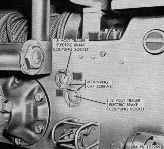
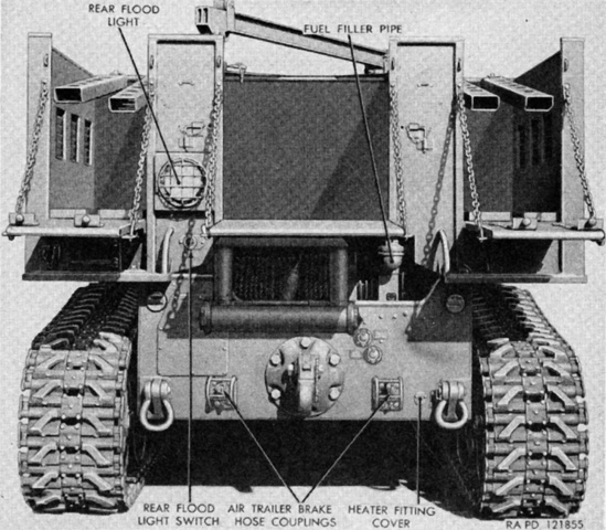
The tractor was also equipped with a Warner electric trailer brake control system for towed loads with this type of braking system, the coupling sockets of which are visible here. The cable plug from the trailer would automatically correctly connect the four wires to the four terminals (trailer tail light wire from the tractor's main light switch; stop light wire from the brake controller; brake operating wire from the brake controller; ground wire from the tractor frame) in the selected socket. The driver could regulate the power of the electric brake system via the load control on the left of his instrument panel. The severity of the braking action could be decreased for lighter loads by turning the knob counterclockwise. (Picture from TM 9-788/TO 19-75AJ-66 38-ton High Speed Tractor M6.)

The electric and air brake control units were mounted to the front of the driver. (Picture from TM 9-788/TO 19-75AJ-66 38-ton High Speed Tractor M6.)

The front pintle is seen assembled on the left and exploded on the right. It was used to maneuver artillery pieces into position for emplacement and was rigidly bolted to the hull front. (Picture from TM 9-1788 Ordnance Maintenance--Tractor, High-speed, 38-ton, M6--Power Train, Suspension, Body, and Equipment.)

The rear pintle, on the other hand, was used for pulling the heavy ordnances and contained a volute spring to cushion towing shocks. (Picture from TM 9-1788 Ordnance Maintenance--Tractor, High-speed, 38-ton, M6--Power Train, Suspension, Body, and Equipment.)
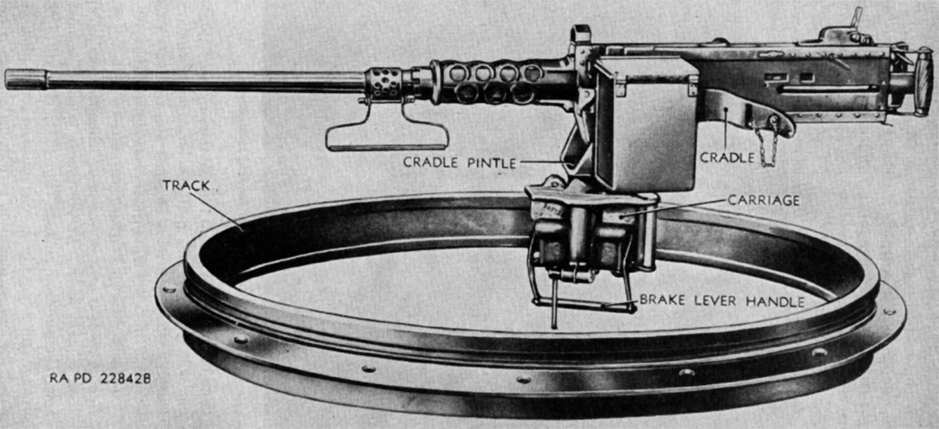
A .50cal M2HB is mounted on the carriage of the ring mount M49C. (Picture from TM 9-788/TO 19-75AJ-66 38-ton High Speed Tractor M6.)
The air compressor system could also be used to inflate pneumatic tires, and a hose for this purpose was carried on the tractor. The air pressure gage on the instrument panel could be used as a tire pressure gage during this process. (Picture from TM 9-788/TO 19-75AJ-66 38-ton High Speed Tractor M6.)
