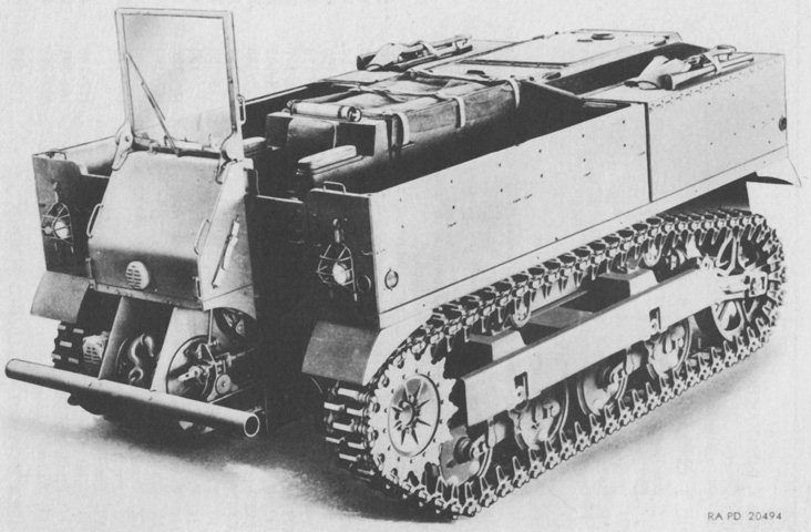
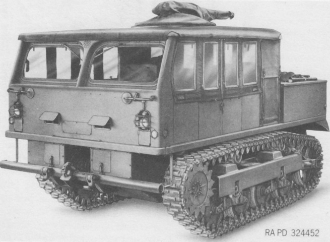
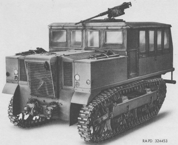
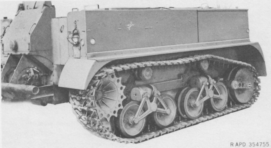
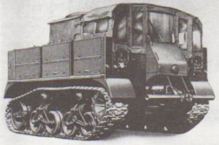
13-ton High-speed Tractor M5.
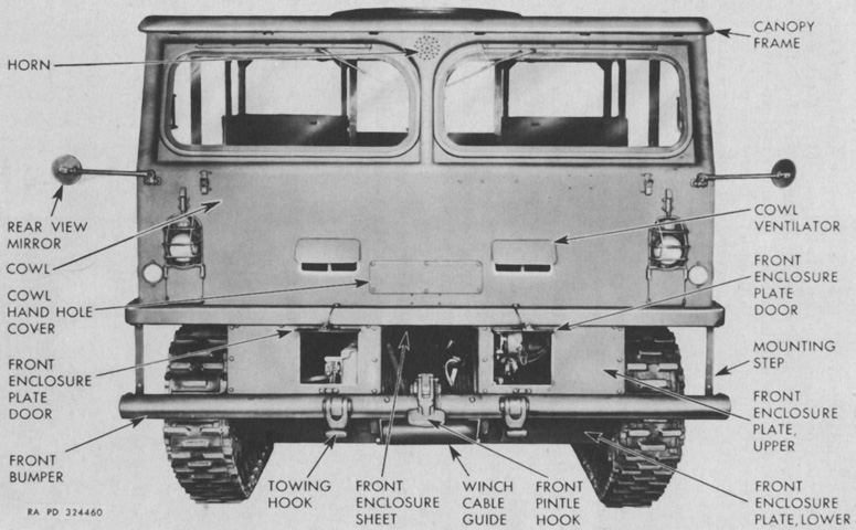
The light tank-style suspension is apparent behind the suspension frame, and parallel grouser light tank tracks are fitted as well. The driver was seated at the front center, and his windshield is erected here. The winch and its hook can be seen behind the front bumper. (Picture from TM 9-786 13-ton High-speed Tractors M5, M5A1, M5A2 and M5A3.)
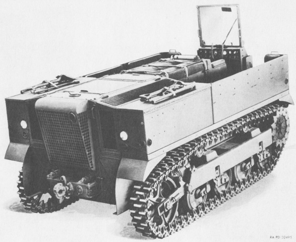
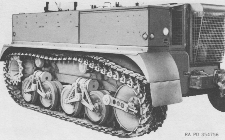
The mesh cover over the cooling fan of the centrally-mounted engine dominates the rear of the tractor; the engine exhaust pipe can be seen at its upper right corner. (Picture from TM 9-786 13-ton High-speed Tractors M5, M5A1, M5A2 and M5A3.)
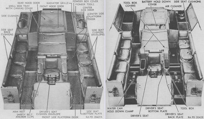
Passenger seating flanked the driver to each side, and shell boxes were between the driver and the engine. Powder boxes occupied the rear corners of the tractor behind the passenger seats. The various stowage boxes and compartments are seen here closed (left) and open (right). A 4lb (1.8kg) CO2 fire extinguisher was stowed below the right platform door. (Picture from TM 9-786 13-ton High-speed Tractors M5, M5A1, M5A2 and M5A3.)
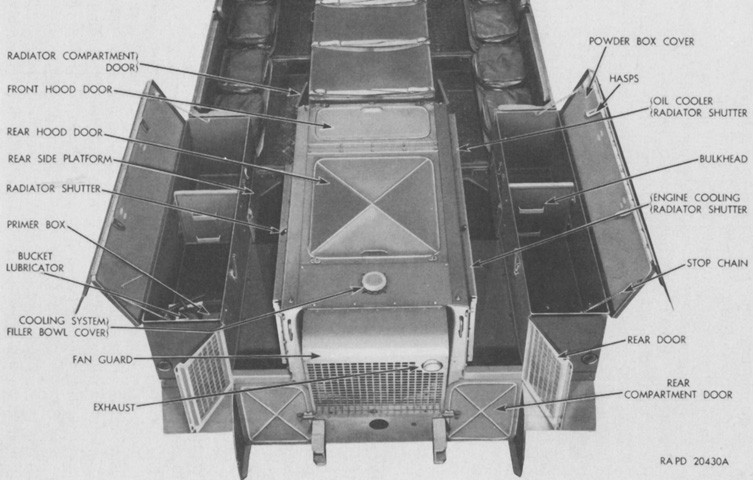
A better look into the open powder boxes is provided here, as well as the action of the outside-hinged rear doors. (Picture from TM 9-786 13-ton High-speed Tractors M5, M5A1, M5A2 and M5A3.)
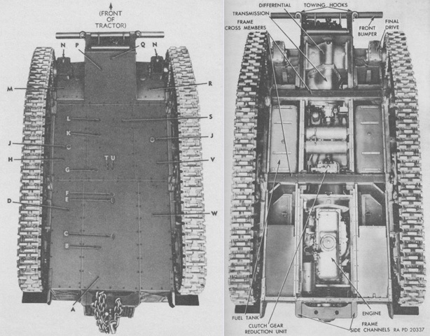
Covers on the tractor's underside are shown secured on the left and removed on the right. The legend for the left image is: A. Center rear bottom plate. B. Oil pan (crankcase) drain valve access hole. C. Oil pan (crankcase) drain plug access hole cover. D. Right rear bottom plate. E. Flywheel housing drain plug access hole cover. F. Clutch housing drain plug access hole. G. Radiator drain valve drain hole. H. Right center bottom plate. J. Fuel tank drain plug access holes. K. Air reservoir tank drain cock access holes. L. Transmission and differential oil filter drain plug access hole. M. Right front bottom plate. N. Final drive drain plug. P. Center front bottom plate. Q. Transmission and differential drain plug access hole. R. Left front bottom plate. S. Center bottom center plate. T. Clutch reduction gear housing oil level valve access hole. U. Clutch reduction gear housing drain plug access hole. V. Left center bottom plate. W. Left rear bottom plate. (Picture from TM 9-786 13-ton High-speed Tractors M5, M5A1, M5A2 and M5A3.)
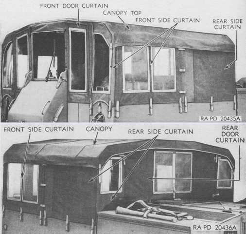
The canopy top is seen from the front in the top of the image and from the rear at the bottom of the picture. The canopy top and side curtains were stowed under the side seats when disassembled. The slip-fit pipes and brackets that comprised the framework were color coded to hasten assembly, which took place on the ground and after which the assembly was lifted onto the tractor. (Picture from TM 9-786 13-ton High-speed Tractors M5, M5A1, M5A2 and M5A3.)
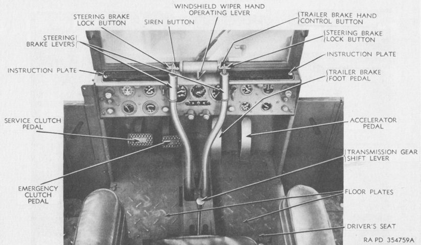
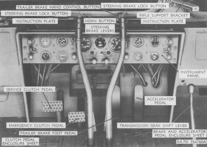
The driver's controls are labeled in this picture. The service clutch pedal was used to disengage the clutch and to select high or low clutch range. To change the clutch range, the pedal was pushed through the spring-loaded stop normally used to disengage the clutch and all the way to the floor. When the clutch was then fully released, it would be in the opposite range as before. The tractor was to be placed in motion using the clutch's low range, and could be switched to high range once ~2,500rpm was reached, after which rpm would drop to ~1,500. Changing from the clutch's high to low ranges required the engine to be at ~1,500 rpm, and after the change rpm would increase to ~2,500. Lights on the driver's instrument panel indicated which clutch range was currently being used. Shifting the transmission speeds required double-clutching, and each transmission speed was accompanied with shifting the clutch range, depending on if the tractor was accelerating or decelerating.
The emergency clutch pedal was used to engage the clutch when little air pressure remained in the system and the clutch power cylinders were inoperative. It was necessary first to depress the service clutch pedal all the way to the floor, and since no air pressure was available to act upon the service clutch pedal, it would remain in the depressed position. Pressing the emergency clutch pedal would engage the clutch and return the service clutch pedal to its raised position. If the driver wanted the clutch to remain in the same range, however, the operation of the service clutch and emergency clutch pedals would need to be repeated, because the clutch range would still change each time the service clutch pedal was depressed all the way.
The trailer brakes could be actuated via a foot pedal or by a button on the inside top of the right steering lever. (Picture from TM 9-786 13-ton High-speed Tractors M5, M5A1, M5A2 and M5A3.)
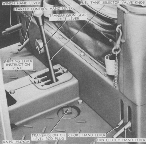
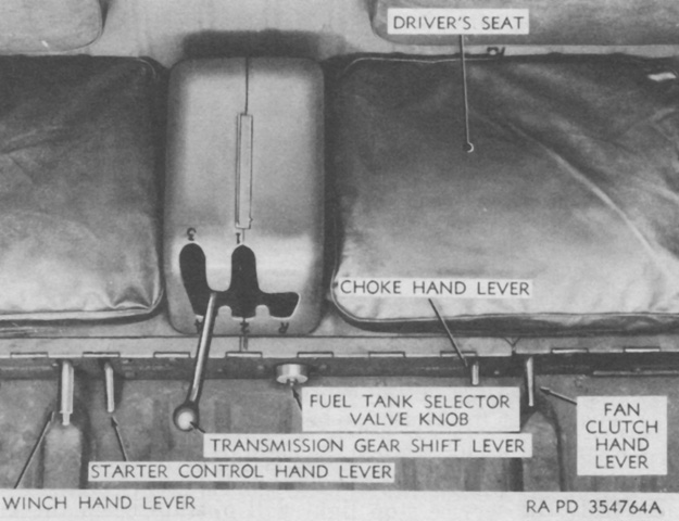
Controls at the front of the driver's seat are labeled here. Note that the captions for the transmission gear shift lever and fuel tank selector valve knob have been switched. The fuel tank selector valve knob worked by shutting off both fuel tanks from the fuel pump when the pointer pointed down, and fuel was drawn from either the right or left tank with the pointer aimed to that respective side. The fan clutch was engaged with the fan clutch lever in the lower position, and disengaged when the lever was raised. The fan clutch was to be disengaged only when the fan guard was open or when the tractor was fording. The starter switch was closed when the starter control hand lever was raised, thereby operating the starter. The winch hand lever had three positions: the center was for neutral, the lever was pressed down for unwind, and the lever was raised for wind. (Picture from TM 9-786 13-ton High-speed Tractors M5, M5A1, M5A2 and M5A3.)
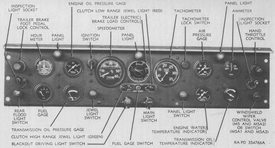
The driver's instrument panel is detailed in this picture. (Picture from TM 9-786 13-ton High-speed Tractors M5, M5A1, M5A2 and M5A3.)
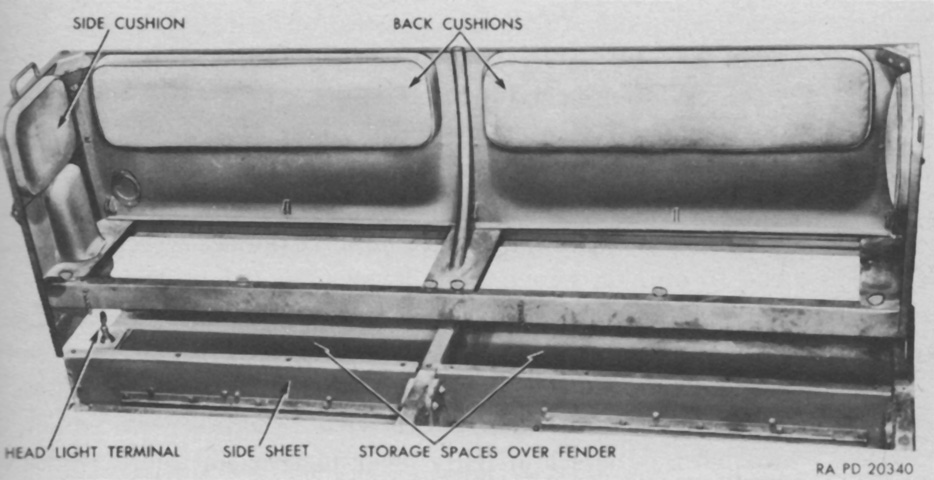
This image highlights the side seats. The bottom cushions have been taken off to prepare the seats for removal. When present, the seat cushion envelopes could each hold two blankets, and a pocket for a rubber pad was sewn into each envelope. The seat cushion envelopes snapped into place, and each one featured a carrying handle. (Picture from TM 9-786 13-ton High-speed Tractors M5, M5A1, M5A2 and M5A3.)
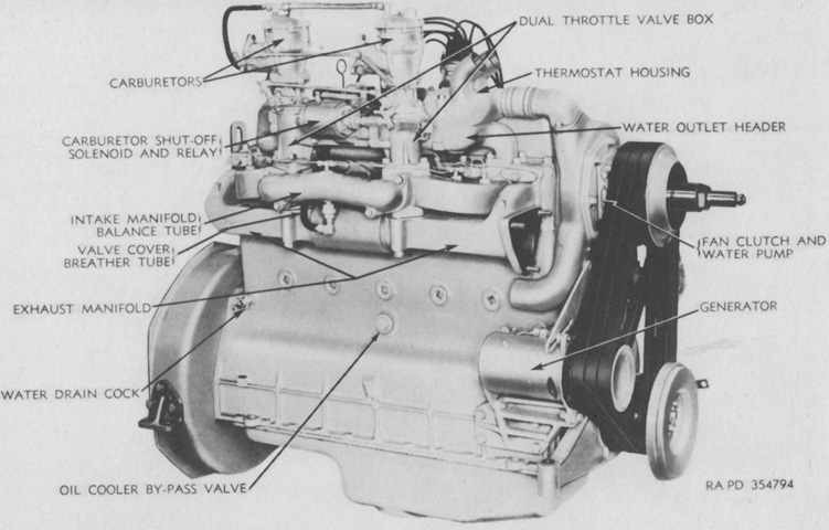
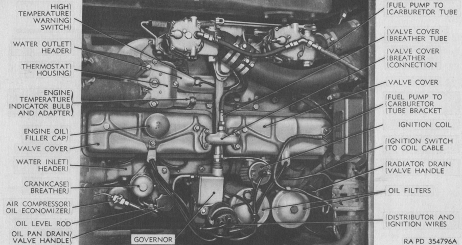
The engine's right side is labeled here. It was a valve-in-head design with dual carburetors and a 6.5:1 compression ratio. The flywheel end was considered the rear of the engine, and this faced the front of the tractor. (Picture from TM 9-786 13-ton High-speed Tractors M5, M5A1, M5A2 and M5A3.)
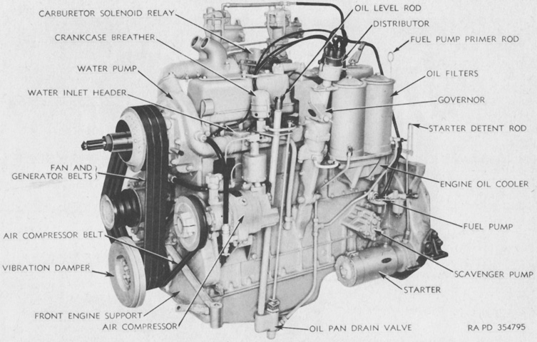
The engine is seen from the opposite side. Bore and stroke were 4¾" and 5⅜" (12.1cm and 13.65cm), respectively, for a displacement of 571.7in³ (9.368L). (Picture from TM 9-786 13-ton High-speed Tractors M5, M5A1, M5A2 and M5A3.)
The engine is mounted in this image. The engine was 65" (165cm) long, 37¾" (95.89cm) wide, 56.5" (144cm) tall, and weighed 2,026lb (919.0kg) without the clutch but including accessories. (Picture from TM 9-786 13-ton High-speed Tractors M5, M5A1, M5A2 and M5A3.)
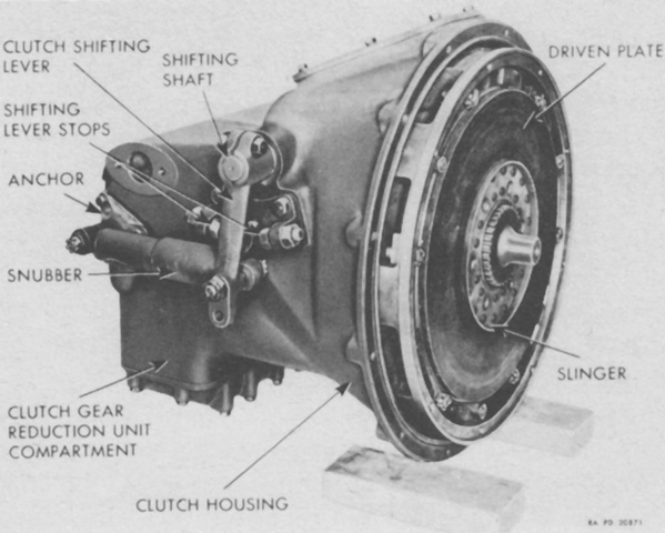
The heavy-duty clutch was a dual-range unit operated by pneumatic pressure. It was comprised of two separate clutches combined into a single assembly, which permitted changing the gear ratio without changing the transmission lever simply by pressing the service clutch pedal all the way to the floor and releasing it. Either of the two driven plates were engaged by moving the central pressure plate forwards or backwards. The clutch's high range was engaged by sliding the driven plate toward the engine flywheel, and low range was used by engaging the driven plate toward the clutch's back plate. In high range, power was transmitted directly to the propeller shaft via an internal shaft, and in low range power was transmitted via an external shaft through a gear reduction unit. (Picture from TM 9-786 13-ton High-speed Tractors M5, M5A1, M5A2 and M5A3.)
The transmission was a constant-mesh, helical-gear type with four forward and one reverse gear ratios. The winch was also driven from the transmission. The controlled differential received power from the transmission through a bevel gear, and transmitted power to the final drive reduction gears. (Picture from TM 9-786 13-ton High-speed Tractors M5, M5A1, M5A2 and M5A3.)
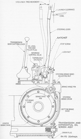
Two three-shoe, double-anchor, external-contracting steering brakes were housed in the controlled differential. Pulling back on a steering lever actuated the brake on that side, steering or slowing/stopping the tractor depending on if one or both levers were pulled simultaneously. (Picture from TM 9-786 13-ton High-speed Tractors M5, M5A1, M5A2 and M5A3.)
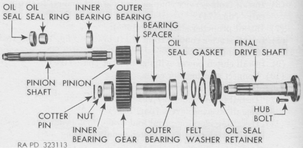
An exploded view of the final drive gearing and shafts is provided here. Each final drive contained a pair of spur reduction gears that were splash-lubricated by oil in the final drive housing. (Picture from TM 9-786 13-ton High-speed Tractors M5, M5A1, M5A2 and M5A3.)
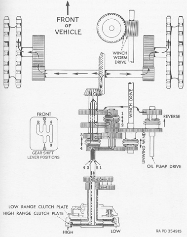
The assembled powertrain is diagrammed in this drawing. The two clutch plates are visible, with the high range's direct shaft and the low range's reduction gearing illustrated. (Picture from TM 9-786 13-ton High-speed Tractors M5, M5A1, M5A2 and M5A3.)
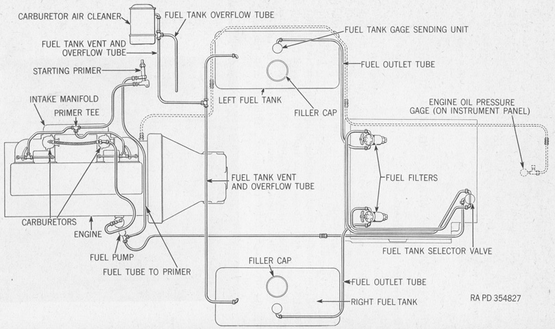
A fuel tank was mounted on each side in the center of the tractor under the platform doors. (Picture from TM 9-786 13-ton High-speed Tractors M5, M5A1, M5A2 and M5A3.)
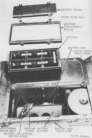
A 12-volt, 168-ampere-hour battery was housed at the upper right front corner of the engine compartment. It is seen here removed from the battery box with the hold-down frame and cover illustrated. (Picture from TM 9-786 13-ton High-speed Tractors M5, M5A1, M5A2 and M5A3.)
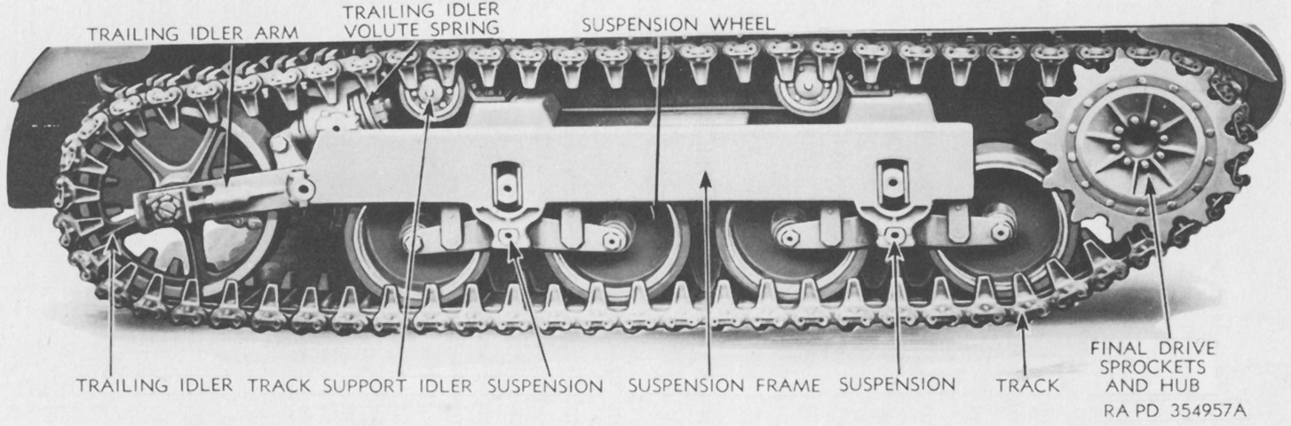
The vertical volute spring suspension was similar to that found in light tanks, and was supported in a frame attached to the hull with studs, lockwashers, and nuts. (Picture from TM 9-786 13-ton High-speed Tractors M5, M5A1, M5A2 and M5A3.)
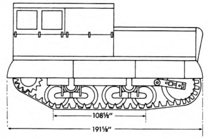
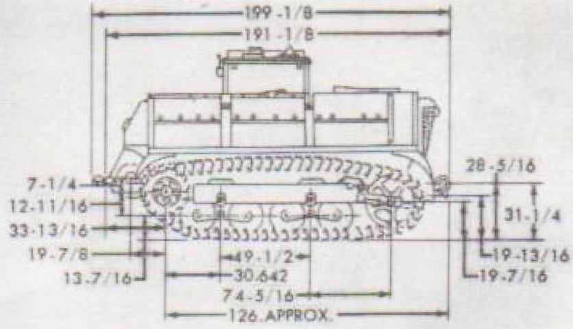
Note that the ground contact length did not include the trailing idler on hard ground. Penetration into softer ground would lengthen the ground contact length and lower the ground pressure. (Picture from TM 9-2800 Standard Military Motor Vehicles.)
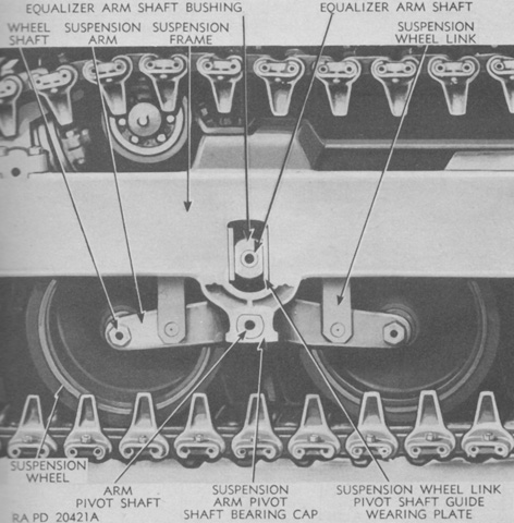
Though similar to the light tank suspension, that found in the high-speed tractor M5 was not identical. Each suspension bogie utilized a single volute spring instead of the two found in light tank bogies. (Picture from TM 9-786 13-ton High-speed Tractors M5, M5A1, M5A2 and M5A3.)
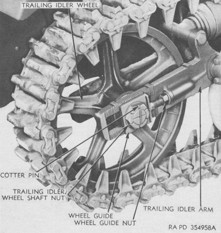
In order to adjust track tension, the trailing idler wheel shaft nuts were loosened after their cotter pins were removed, thereby freeing serrations on the wheel guide from serrations on the idler arm. Then the inside and outside wheel guide nuts were turned the same amount so that, when the correct tension was achieved, the inner and outer wheel guides were the same number of serrations away from the idler arm's front serrations. (Picture from TM 9-786 13-ton High-speed Tractors M5, M5A1, M5A2 and M5A3.)
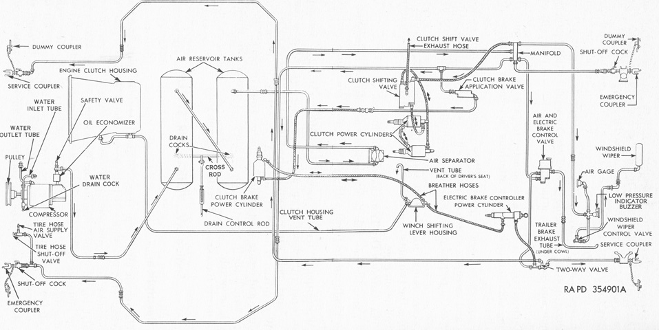
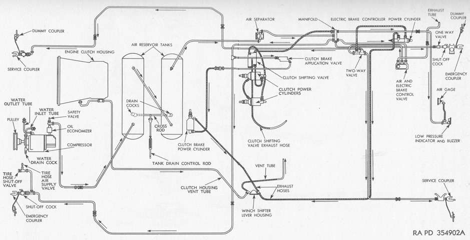
The tractor's air system is the subject of this sketch. A rotary air compressor was belt driven off the engine's crankshaft and cooled by the engine cooling system. The system was kept at 80-100psi (5.6-7.0kg/cm²) by a governor on the compressor, and a safety valve opened at 172-180psi (12.1-12.6kg/cm²) to prevent damage. From the two storage tanks, air flowed through a manifold plumbed to the air pressure gage, low pressure indicator and buzzer, windshield wiper, clutch shifting valve, clutch brake application valve, air and electric brake control valve, and emergency hose couplings at the tractor's front and rear. (Picture from TM 9-786 13-ton High-speed Tractors M5, M5A1, M5A2 and M5A3.)
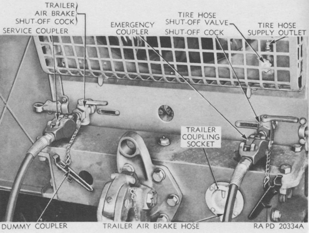
Air outlets at the tractor's rear are labeled here. Similar couplers were found at the front, except that the right coupler was the service coupler and the left was the emergency coupler. Dummy couplers were provided to prevent loss from the air tubes when not in use. The front outlets did not include a tire hose supply outlet. (Picture from TM 9-786 13-ton High-speed Tractors M5, M5A1, M5A2 and M5A3.)
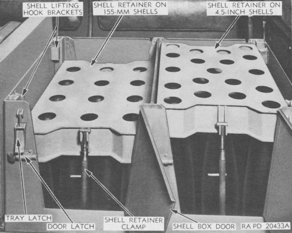
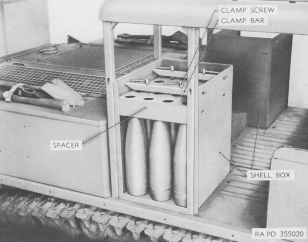
The shell box was between the driver and the engine, and doors on each side facilitated the stowage or removal of shells. Two shell racks were provided to hold 105mm, 155mm, or 4.5" shells, and retainers stabilized the shells from the top. 105mm shells could be stowed in both compartments by placing spacers in the compartment bottom and lying the shells in crosswise. (Picture from TM 9-786 13-ton High-speed Tractors M5, M5A1, M5A2 and M5A3.)
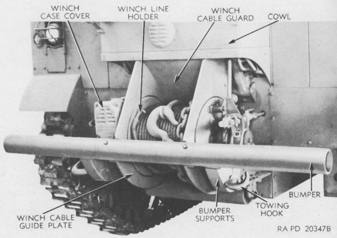
The Gar Wood Model US 15T winch is highlighted in this picture. A cable roller was provided for rearward winching in the M5 and M5A2, while the M5A1 and M5A3 featured a cable guide for this purpose. The dual range clutch permitted two winding and unwinding speeds, and the winch speed was controlled by accelerating the engine. An automatic brake held the winch worm shaft when the engine clutch was disengaged, and a drag brake prevented the drum from spinning when the sliding winch clutch was disengaged and the cable was pulled off by hand. (Picture from TM 9-786 13-ton High-speed Tractors M5, M5A1, M5A2 and M5A3.)
The M5A1 provided a permanent superstructure for attachment of the canopy top. Seating and stowage was rearranged, but mechanically it was similar to the M5. The antiaircraft machine gun is mounted, but is under its canvas cover. (Picture from TM 9-786 13-ton High-speed Tractors M5, M5A1, M5A2 and M5A3.)
The front of the new cab is labeled here. The side and rear curtains and canopy top are not present. The windshield wipers were electrically operated instead of pneumatically, as in the M5. (Picture from TM 9-786 13-ton High-speed Tractors M5, M5A1, M5A2 and M5A3.)
The machine gun is visible in this view, with the barrel secured. (Picture from TM 9-786 13-ton High-speed Tractors M5, M5A1, M5A2 and M5A3.)
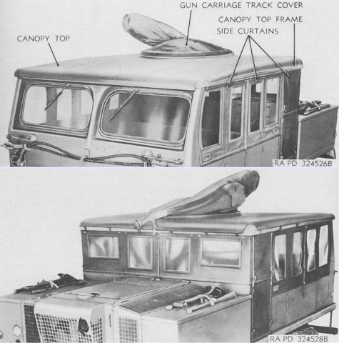
The canopy is highlighted here from the front (top) and rear (bottom). The side curtains could be removed and stowed in compartments on the inside without removing the canopy top from its frame. (Picture from TM 9-786 13-ton High-speed Tractors M5, M5A1, M5A2 and M5A3.)
With the driver moved to the left front corner, the transmission's gear shift lever now appeared at his right instead of directly ahead. (Picture from TM 9-786 13-ton High-speed Tractors M5, M5A1, M5A2 and M5A3.)
The shifting of the driver caused relative displacement of the other controls as shown here. The fire extinguisher was also moved to a recess in the front right corner of the cab. (Picture from TM 9-786 13-ton High-speed Tractors M5, M5A1, M5A2 and M5A3.)
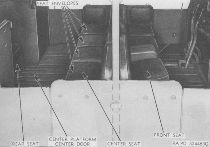
The seating was rearranged to accommodate four men in the front, five in the center facing to the rear, and two men in the rear. The seat cushion envelopes were similar to those found on the M5. (Picture from TM 9-786 13-ton High-speed Tractors M5, M5A1, M5A2 and M5A3.)
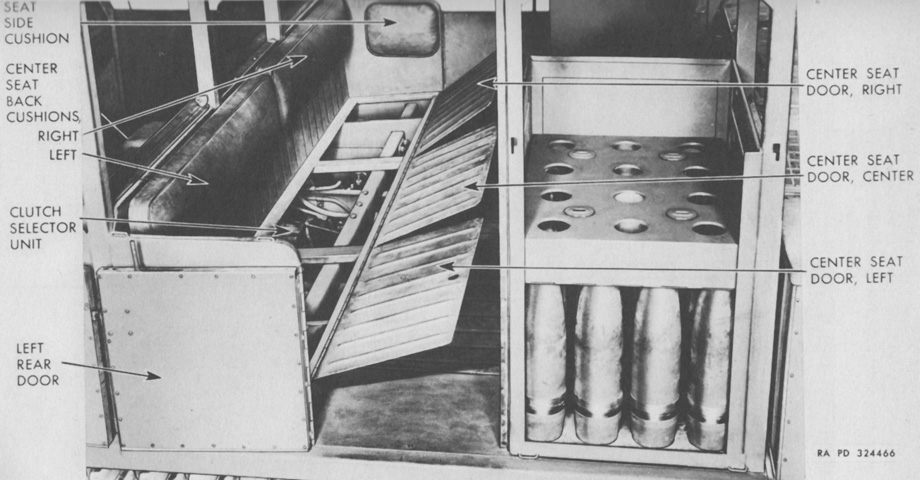
The center seats are swung up, revealing access underneath. The canopy curtains were stowed in compartments opened when the front seat backs were swung forward. The shell box is loaded with 105mm ammunition. (Picture from TM 9-786 13-ton High-speed Tractors M5, M5A1, M5A2 and M5A3.)
The shell boxes were moved to each side of the rear seat. Canvas covers were provided for protection when the boxes were not not being loaded or unloaded. (Picture from TM 9-786 13-ton High-speed Tractors M5, M5A1, M5A2 and M5A3.)
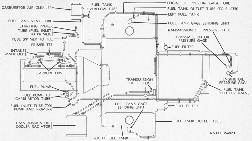
The fuel system can be contrasted to that found in the M5. (Picture from TM 9-786 13-ton High-speed Tractors M5, M5A1, M5A2 and M5A3.)
The air system was similar to the M5's, save for the lack of air-powered windshield wipers. (Picture from TM 9-786 13-ton High-speed Tractors M5, M5A1, M5A2 and M5A3.)
The new horizontal volute spring suspension dispensed with the frames attached to the hull, and dual wheels were used with the wide single-pin, center-guide track. (Picture from TM 9-786 13-ton High-speed Tractors M5, M5A1, M5A2 and M5A3.)
A trailing idler wheel was retained with the suspension switch. (Picture from TM 9-786 13-ton High-speed Tractors M5, M5A1, M5A2 and M5A3.)
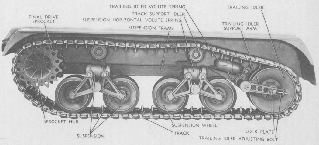
Nomenclature for the horizontal volute spring suspension is given here. The idler retained its own spring, and track tension was adjusted in a similar manner to the earlier suspension. (Picture from TM 9-786 13-ton High-speed Tractors M5, M5A1, M5A2 and M5A3.)
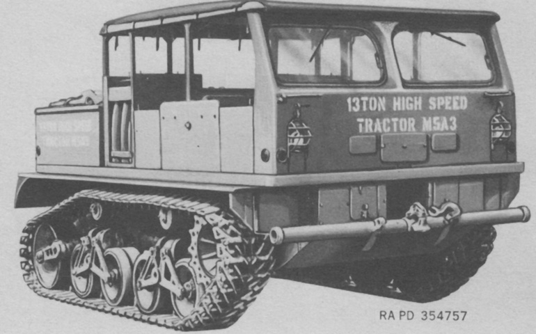
The horizontal volute spring suspension was combined with the steel cab in the M5A3. (Picture from TM 9-786 13-ton High-speed Tractors M5, M5A1, M5A2 and M5A3.)
The rearranged shell boxes lined the fenders and opened to the outside, easing access to their contents. The canvas cover is erected over the passenger compartment, and the machine gun mount is visible to the rear. (Picture from TM 9-2800-1/TO 19-75A-89 Military Vehicles (Ordnance Corps Responsibility).)
The machine gun mount is more easily seen in this sketch with the canvas canopy stowed. (Picture from TM 9-2800-1/TO 19-75A-89 Military Vehicles (Ordnance Corps Responsibility).)
