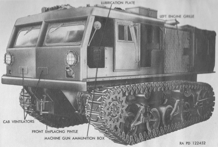
18-ton High Speed Tractor M4.
The tractor is shown here from the left front. Note the single-wheel return rollers characteristic of later-production machines. (Picture from TM 9-785 18-ton High Speed Tractors M4, M4A1, M4C, and M4A1C.)
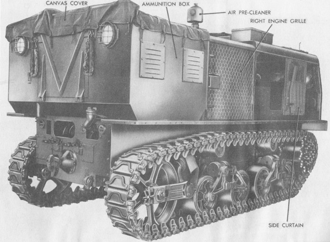
This tractor is carrying the 155mm or 240mm cargo box, which had a large downward-hinged door at the rear. Openings for access to the winch are visible on the hull rear, and the fuel filler is just inboard of the right-side taillight. (Picture from TM 9-785 18-ton High Speed Tractors M4, M4A1, M4C, and M4A1C.)
The 90mm ammunition box is shown here, with doors that could be unlatched and swung down to access the stowed shells. (Picture from TM 9-2800-1/TO 19-75A-89 Military Vehicles (Ordnance Corps Responsibility).)
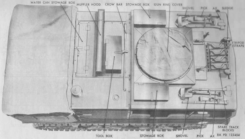
Stowage for pioneer tools, spare track shoes, water cans, and the machine gun tripod was provided on the roof of the cab. (Picture from TM 9-785 18-ton High Speed Tractors M4, M4A1, M4C, and M4A1C.)
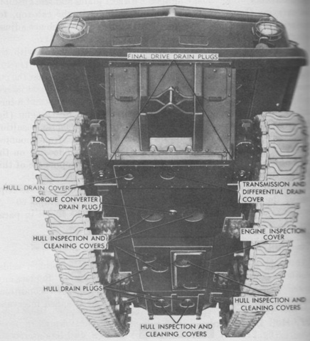
The various drain plugs and access covers found on the hull underside are labeled in this image. (Picture from TM 9-785 18-ton High Speed Tractors M4, M4A1, M4C, and M4A1C.)
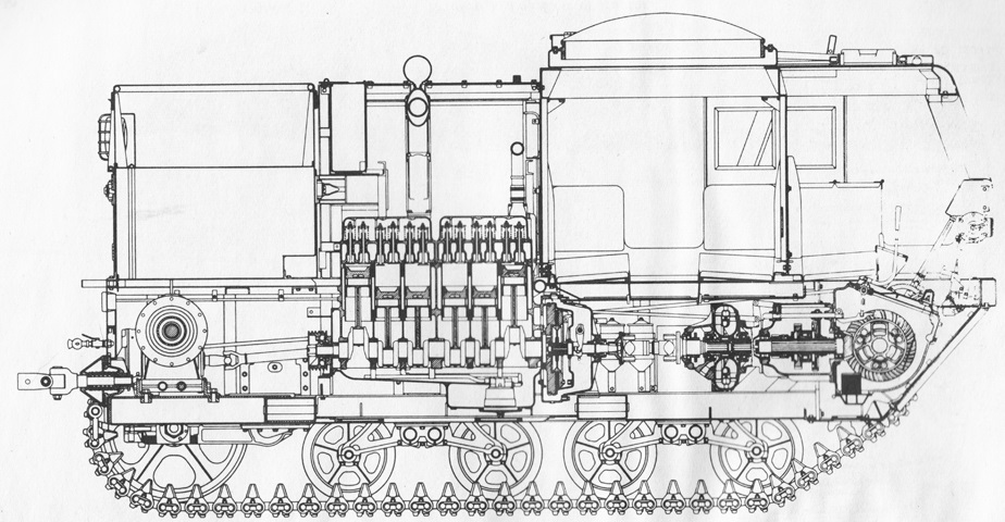
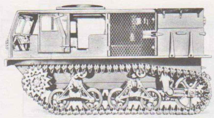
The tractor's internal arrangement is sketched here. The crew seats are visible behind the driver's position, and the winch can be seen at the rear. The engine was mounted centrally, with power flowing forward to the drive sprockets. (Picture from TM 9-785 18-ton High Speed Tractors M4, M4A1, M4C, and M4A1C.)
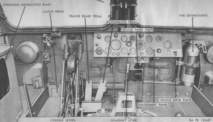
The driver's position is labeled here. The tractor was compatible with both electric and air trailer brakes, depending on the design of the trailer, and the trailer brake pedal would actuate whatever braking system the trailer used. The tractor itself was stopped via the steering levers. (Picture from TM 9-785 18-ton High Speed Tractors M4, M4A1, M4C, and M4A1C.)
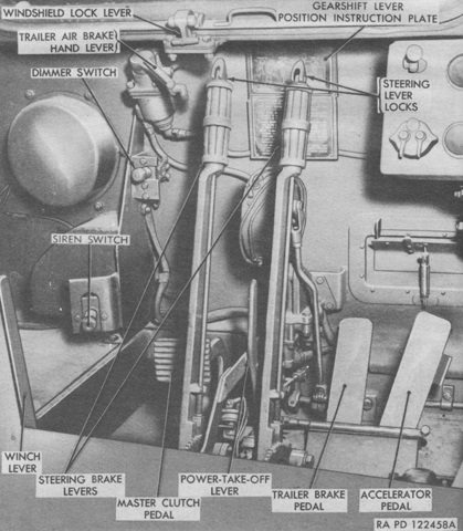
Trailer air brakes could also be operated by a hand control at the driver's front left. (Picture from TM 9-785 18-ton High Speed Tractors M4, M4A1, M4C, and M4A1C.)
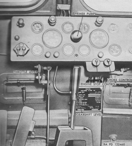
The gearshift lever and controls on the instrument panel are labeled. (Picture from TM 9-785 18-ton High Speed Tractors M4, M4A1, M4C, and M4A1C.)
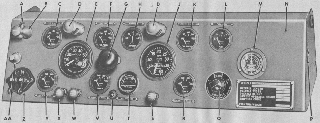
The driver's instrument panel is detailed in this picture. A. Main light switch knob. B. Main light switch. C. Engine oil pressure gage. D. Panel light. E. Speedometer. F. Converter oil pressure gage. G. Primer pump. H. Ammeter. J. Tachometer. K. Transmission oil pressure gage. L. Fuel gage. M. Hour meter. N. Instrument panel. P. Accessory light socket. Q. Load control. R. Transmission oil temperature gage. S. Panel light switch. T. Air pressure gage. U. Low air pressure warning light. V. Converter oil temperature gage. W. Rear flood light switch. X. Blackout light switch. Y. Engine temperature gage. Z. Windshield wiper switch. AA. Starter button. (Picture from TM 9-785 18-ton High Speed Tractors M4, M4A1, M4C, and M4A1C.)
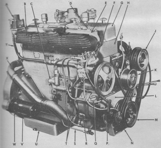
The Waukesha 145GZ engine is shown here from the left rear. It was a valve-in-head design with dual carburetors. Bore was 5⅜" (13.65cm) and stroke was 6" (15cm) for a displacement of 817in³ (13.4L). Its weight with accessories was ~2,150lb (~975kg), and it was 55¼" (140.3cm) long, 48" (120cm) high, and 35" (89cm) wide. The flywheel faced forward when mounted, and the flywheel end was considered the front. A. Thermostat housing. B. Exhaust manifold. C. Oil cooler. D. Temperature sending unit. E. Water manifold. F. Air compressor. G. Rocker arm cover. H. Cylinder head. J. Fan drive gear. K. Fan belt tightener. L. Timing gear cover. M. Crankshaft pulley. N. Engine support. P. Air compressor belt tightener. Q. Oil filler plug. R. Water pump. S. Water drain pipe. T. Water, air compressor pipes. U. Oil pan. V. Starter. W. Flywheel housing. X. Water inlet pipe. Y. Water by-pass pipe. (Picture from TM 9-785 18-ton High Speed Tractors M4, M4A1, M4C, and M4A1C.)
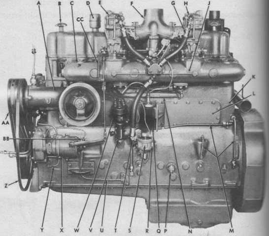
The engine's compression ratio was 6:1, and its maximum governed speed was 2,100rpm. Its right side is labeled in this image. A. Fan drive gear. B. Handwheel. C. Intake manifold. D. Oil filler cap. E. Rear carburetor. F. Air inlet connection. G. Fuel hose. H. Front carburetor. J. Primer manifold. K. Cylinder block. L. Valve lifter cover. M. Oil pipes. N. Intake manifold water pipe. P. Oil pressure sending unit. Q. Ignition coil. R. Fuel pump suction connection. S. Fuel pump. T. Fuel pump discharge line. U. Governor drain oil pipe. V. Tachometer drive adapter. W. Ignition distributor. X. Governor. Y. Air compressor oil pipe. Z. Generator belt. AA. Fan drive gear belt. BB. Wing nut. CC. Governor-to-carburetor rod spring. (Picture from TM 9-785 18-ton High Speed Tractors M4, M4A1, M4C, and M4A1C.)
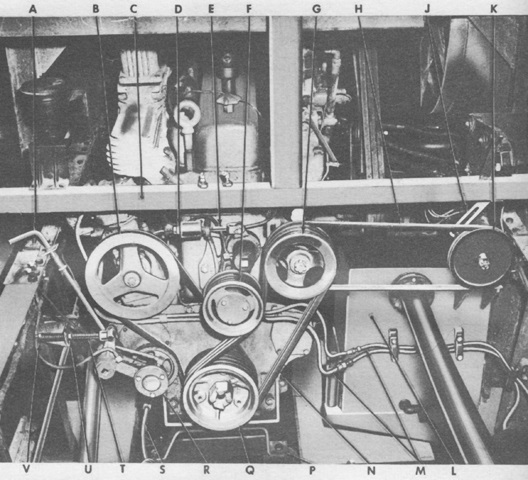
The engine is shown here from the rear mounted in the tractor. A. Cooling system drain valve. B. Air compressor pulley. C. Radiator supporting frame. D. Fan drive belt tightener adjusting nut. E. Fan drive belt tightener adjusting bolt. F. Fan drive belt tightener. G. Fan drive gear. H. Generator belt. J. Generator adjusting link. K. Generator. L. Fuel tank. M. Air lines. N. Fan drive belts. P. Rear engine support. Q. Crankshaft pulley. R. Air compressor belt tightener. S. Water drain line. T. Air compressor belt tightener adjusting bolt. U. Air compressor belt tightener lock nut. V. Air compressor belt tightener adjusting nut. (Picture from TM 9-785 18-ton High Speed Tractors M4, M4A1, M4C, and M4A1C.)
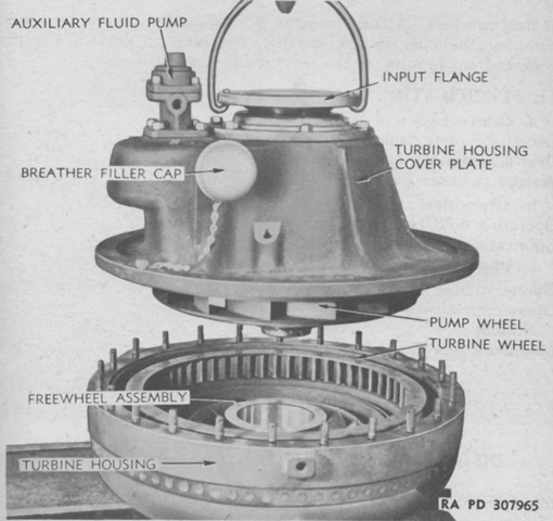
The twin-disk model T-10010 torque converter is being disassembled here. Mounted at the rear of the transmission, the torque converter cycled fluid through three sets of turbine blades in order to allow smooth and shockless starting and acceleration, prevent clutch slippage, and prevent stalling under heavy loads. The torque converter impeller was coupled to the engine by the propeller and clutch shafts, and its output shaft was connected to the transmission input shaft. The torque converter was 15½" (39.4cm) long from the coupling flange to the turbine hub face, 18⅞" (47.943cm) in overall diameter excluding bosses, and weighed 350lb (160kg) without its 14 quarts (13L) of fluid and 2⅓ pints (1.10L) of lubricating oil. (Picture from TM 9-1785A Ordnance Maintenance--Engine, Engine Accessories, and Torque Converter for 18-ton M4 and 38-ton M6 High Speed Tractors.)
A horizontal cross-section of the transmission in neutral is drawn here. It was a selective type with one reverse and three forward speed ranges. The forward ranges were creeper, low, and high. Creeper gear provided the greatest pulling power, but topped out at 7mph (11kph). An engine braking selection on the gearshift lever was used when descending long, steep hills; this slid the range shifter gear into mesh with the internal teeth of the overrunning clutch gear and bevel pinion shaft, so that the engine's braking power was delivered from the input shaft through the low range pinion, overrunning clutch gear, and range shifter gear to the bevel pinion shaft. (Picture from TM 9-1785B Ordnance Maintenance--Power Train, Suspension, and Equipment for 18-ton High Speed Tractor M4.)
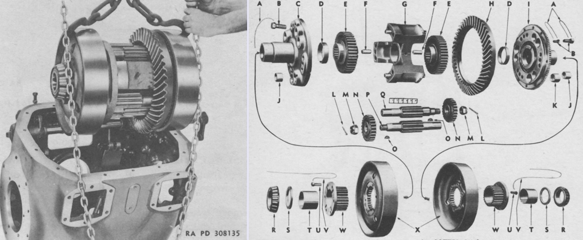
The differential assembly is shown on the left being removed from its housing, and an exploded view is provided on the right. A. Lock wires. B. Cap screws. C. Compensating case cover (right). D. Differential gear bushings. E. Inner differential gears. F. Compensating case dowels. G. Compensating case. H. Bevel gear. I. Compensating case cover (left). J. Compensating case cover bushings (small). K. Compensating case cover bushing (large). L. Cotter pins. M. Slotted nuts. N. Outer differential pinions. O. Keys. P. Differential pinion shaft (right). Q. Differential pinion shaft (left). R. Differential bearing cones. S. Thrust washers. T. Brake drum hub bushings. U. Brake drum hub bolts. V. Lock wires. W. Brake drum hubs. X. Differential brake drums. (Picture from TM 9-1785B Ordnance Maintenance--Power Train, Suspension, and Equipment for 18-ton High Speed Tractor M4.)
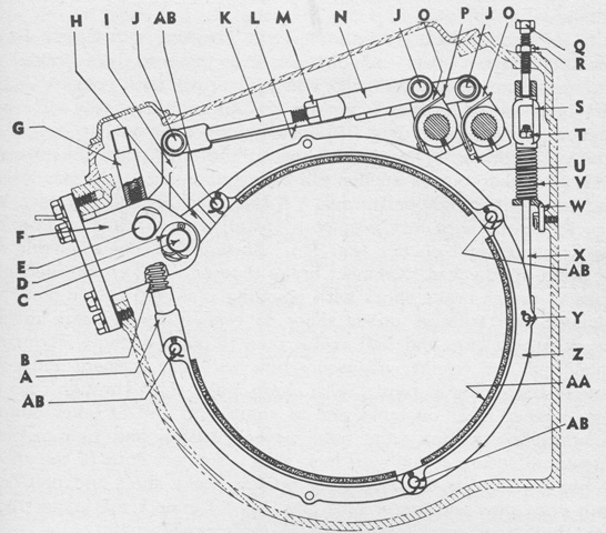
A sectionalized view of a steering brake is sketched in this image. A. Brake shoe yoke. B. Brake shoe spring. C. Brake shoe and bell crank pin. D. Washer. E. Brake shoe anchor pin. F. Steering brake anchor. G. Brake shoe adjusting nut. H. Brake shoe and bell crank connecting link. I. Brake control bell crank. J. Yoke pin. K. Brake control rod, left. L. Brake control rod, right. M. Jam nut. N. Rod yoke. O. Brake lever. P. Lock wire. Q. Stabilizer bolt. R. Lock nut. S. Brake shoe support rod yoke. T. Nut. U. Clamp bolt. V. Support rod spring. W. Support rod guide clip. X. Brake shoe support rod. Y. Support rod pin. Z. Brake shoe. AA. Brake lining. AB. Brake shoe coupling pin. (Picture from TM 9-1785B Ordnance Maintenance--Power Train, Suspension, and Equipment for 18-ton High Speed Tractor M4.)
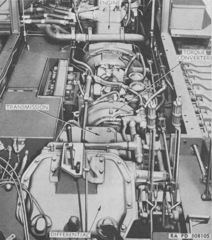
The cab has been removed from this tractor, allowing a view of the installed engine and power train. The fuel tank is on the left of the image, and contains a recess for the tractor's battery. (Picture from TM 9-1785B Ordnance Maintenance--Power Train, Suspension, and Equipment for 18-ton High Speed Tractor M4.)
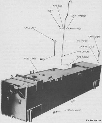
The fabricated steel fuel tank was placed on the right side of the hull. The recess in the tank for the tractor's batteries can be seen. (Picture from TM 9-1785B Ordnance Maintenance--Power Train, Suspension, and Equipment for 18-ton High Speed Tractor M4.)
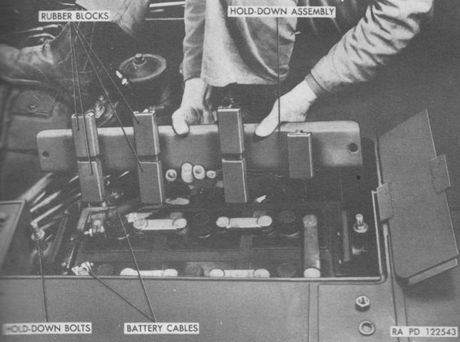
A 12-volt wet cell battery was housed in a bracket on the right side of the hull. (Picture from TM 9-785 18-ton High Speed Tractors M4, M4A1, M4C, and M4A1C.)
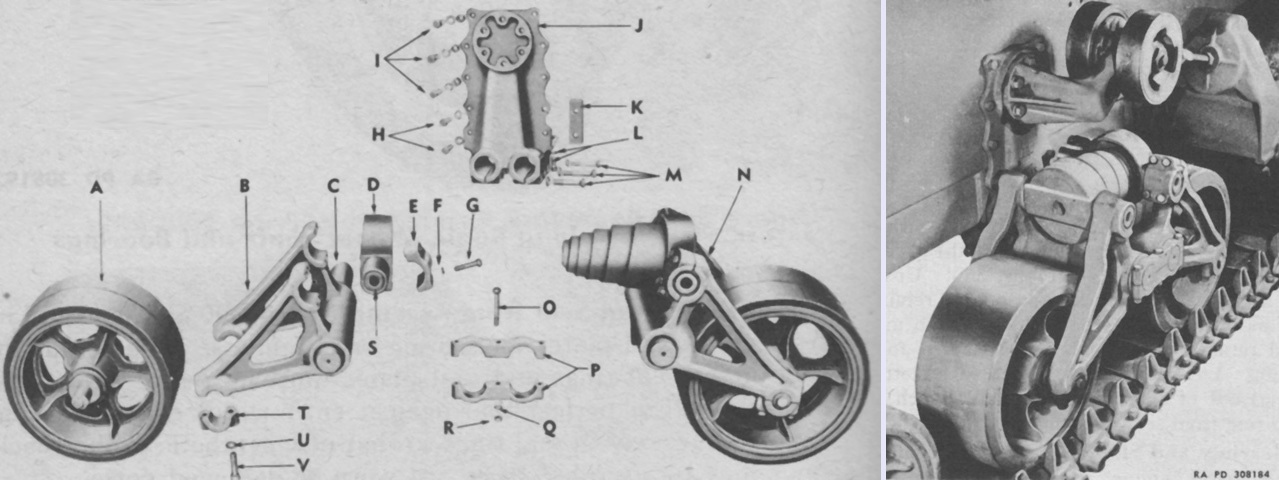
An exploded view of a suspension bogie is provided on the left, and the assembled bogie can be seen on the right. A. Bogie wheel. B. Bogie arm. C. Hinge pin. D. Spring seat. E. Bogie arm cap. F. Lock washer. G. Cap screw. H. Cap screws and lock washers. I. Bolts and lock washers. J. Bogie bracket. K. Bracket filler spacer. L. Capscrew and lock washer. M. Capscrews and lock washers. N. Bogie assembly (right). O. Bolt. P. Hinge pin tie bar. Q. Cap screw. R. Nut. S. Spring seat bushing. T. Bogie arm cap. U. Lock washer. V. Cap screw. (Picture from TM 9-1785B Ordnance Maintenance--Power Train, Suspension, and Equipment for 18-ton High Speed Tractor M4.)
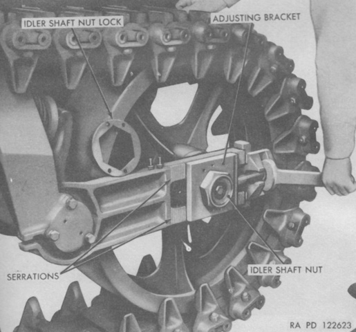
To adjust track tension, the nuts on the idler adjusting bracket bolts were turned to move the wheel to the front or rear. There were adjusting bolts on the inside and outside of each idler wheel, and the inner and outer nuts were to be turned evenly. The adjusting brackets were held tightly to serrations on the idler yoke by the idler shaft nut. The idler shaft nut needed to be loosened to allow the adjusting bracket to move. Note also the idler wheel's volute spring visible on the left. (Picture from TM 9-785 18-ton High Speed Tractors M4, M4A1, M4C, and M4A1C.)
The early dual-wheel return roller above can be contrasted with the later single-wheel return roller below. The legend for the upper image is: A. Nuts. B. Locking washers. C. Rollers. D. Oil seals. E. Cap screws. F. Lock washers. G. Bearing retainers. H. Shims. I. Bearing caps. J. Bearings. K. Bracket. L. Shaft. M. Plug gasket. N. Shaft plug.
The legend for the lower image is: A. Bracket. B. Dowel. C. Dowels. D. Seal gasket. E. Seal rings. F. Seal spring assembly. G. Seal boot. H. Bearing retainer. I. Retainer gaskets. J. Bearings. K. Bearing cups. L. Roller. M. Shims. N. Adjusting bolt washer. O. Lock washer. P. Bearing adjusting bolt. Q. Bearing retainer. R. Plug gasket. S. Shaft plug. T. Cap screws. U. Lock washers. (Picture from TM 9-1785B Ordnance Maintenance--Power Train, Suspension, and Equipment for 18-ton High Speed Tractor M4.)
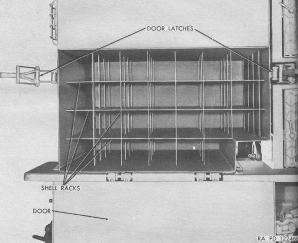
The 90mm ammunition rack has been opened. Loading the box was accomplished by unlatching and lowering the door and then sliding the shells into the stationary racks. (Picture from TM 9-785 18-ton High Speed Tractors M4, M4A1, M4C, and M4A1C.)
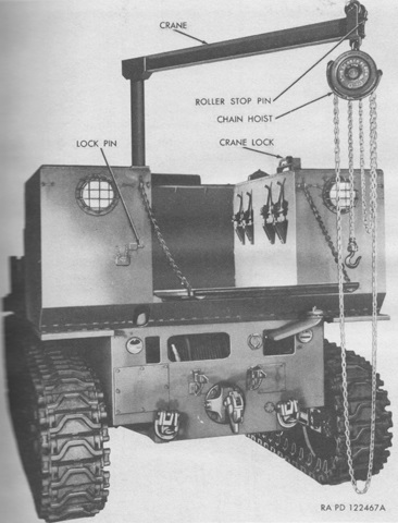
The ammunition box for the larger ammunition could accommodate 155mm, 8", or 240mm shells. Two pairs of ammunition racks were included: one pair had recesses for 155mm shell bases in one side and 8" shell bases in the opposite side. The other pair of racks only had recesses for 240mm shell bases. A chain shell hoist was also provided for these heavy ammunition types. The hoist was adjustable for height and swing, and the chain could be moved along the horizontal rail. The hoist was stowed when not in use. (Picture from TM 9-785 18-ton High Speed Tractors M4, M4A1, M4C, and M4A1C.)
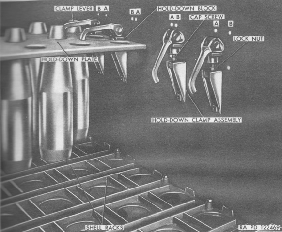
155mm shells are seen here stowed in the cargo box. Hold-down plates were provided for each size of shell, and these were secured by adjustable clamps. (Picture from TM 9-785 18-ton High Speed Tractors M4, M4A1, M4C, and M4A1C.)
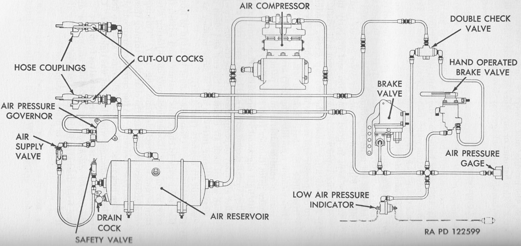
The tractor's air brake control system is diagrammed. The air compressor was a Bendix-Westinghouse Model No.2-UE-7 1/4-VW which was mounted on a mat on the timing gear housing of the cylinder block. It was belt-driven by the main engine, water cooled, and used oil from the main engine's lubrication system. It displaced 7¼ft³ (.205m³) per minute at 1,250rpm, and an unloader valve was opened by a pressure governor when air pressure reached 105psi (7.4kg/cm²) until the pressure dropped below 80psi (5.6kg/cm²). The compressor could be removed if the tractor was primarily towing trailers with electric brakes in very dusty or sandy terrain, as this could cause excess wear to the compressor. (Picture from TM 9-785 18-ton High Speed Tractors M4, M4A1, M4C, and M4A1C.)
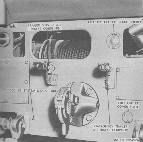
The connections for air and electric trailer brake systems are seen on the rear of the hull. The winch can also be seen in the large central aperture, and the fuel filler is visible at the upper right of the image. (Picture from TM 9-785 18-ton High Speed Tractors M4, M4A1, M4C, and M4A1C.)
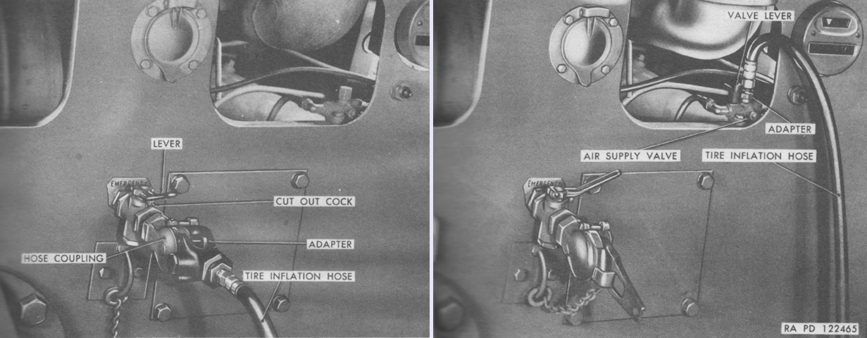
A tire inflation hose was carried on each tractor. When inflating tires needing more than 105psi (7.37kg/cm²) of pressure, the hose was connected to the air supply valve as seen on the right. The valve lever was turned up in order to disable the air pressure governor. (Picture from TM 9-785 18-ton High Speed Tractors M4, M4A1, M4C, and M4A1C.)
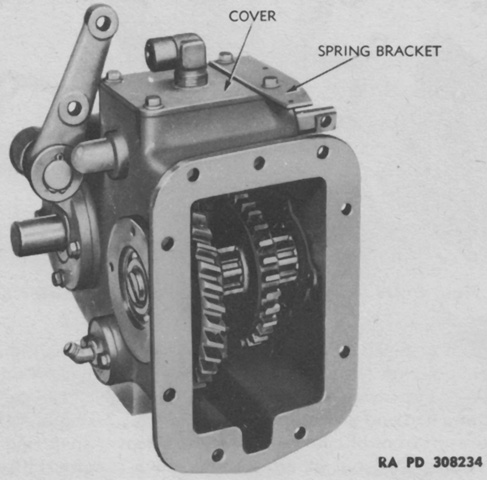
The power take-off was mounted on the transmission case and was driven by the transmission's high range pinion. It was reversible so that the winch drum could be turned in either direction, thereby easing the pay out of the winch cable. A sliding pinion had positions for winding, unwinding, and neutral. (Picture from TM 9-1785B Ordnance Maintenance--Power Train, Suspension, and Equipment for 18-ton High Speed Tractor M4.)
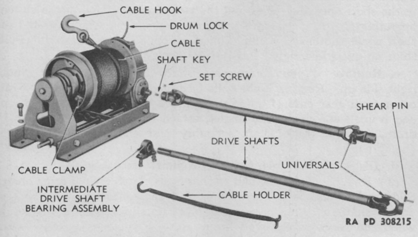
The Gar Wood Model Number 4M718 winch is shown along with its drive shafts. Drive shafts with universals were connected to the winch worm shaft and the power take-off. The winch drum shaft was then driven by the worm and gear in the gear case through a sliding jaw clutch operated by a control lever at the driver's position. An automatic brake on the winch worm shaft held loads when the engine's master clutch was disengaged. (Picture from TM 9-1785B Ordnance Maintenance--Power Train, Suspension, and Equipment for 18-ton High Speed Tractor M4.)
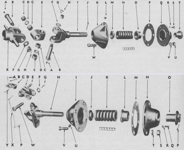
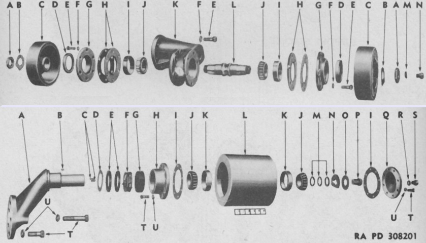
Two towing pintles were provided; the upper image shows that used with the 3" and 90mm antiaircraft guns, and the lower was used with the 155mm, 8", and 240mm ordnances. The former featured a universal swivel and yoke, while the latter had a hook for connecting. The legend for the upper image is: A. Lubrication fittings. B. Yoke cross pins. C. Cross pin bearings. D. Bearing spacers. E. Yoke cross. F. Washers. G. Nuts. H. Cotter pins. I. Pintle fork. J. Cotter pin. K. Rear housing. L. Pipe plug. M. Spring seat. N. Spring. O. Spring seat. P. Housing gasket. Q. Front housing. R. Lock washer. S. Cap screw. T. Pintle stop. U. Nut. V. Lock washer. W. Bolt. X. Yoke.
The legend for the lower image is: A. Cap screw. B. Lock washer. C. Pintle latch. D. Pintle lock. E. Latch pin. F. Nut. G. Cotter pin. H. Pintle hook. I. Rear housing. J. Spring seat. K. Spring. L. Spring seat. M. Housing gasket. N. Front housing. O. Yoke stop. P. Cotter pin. Q. Cap screw. R. Lock washer. S. Nut. T. Lock washer. U. Pipe plug. V. Bolt. W. Lock bolt. X. Hook chain. Y. Latch spring. (Picture from TM 9-1785B Ordnance Maintenance--Power Train, Suspension, and Equipment for 18-ton High Speed Tractor M4.)
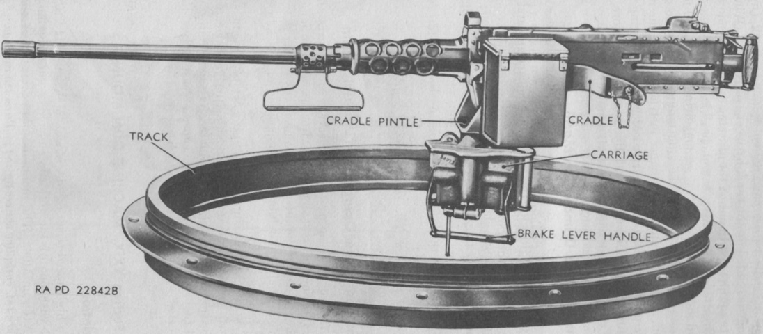
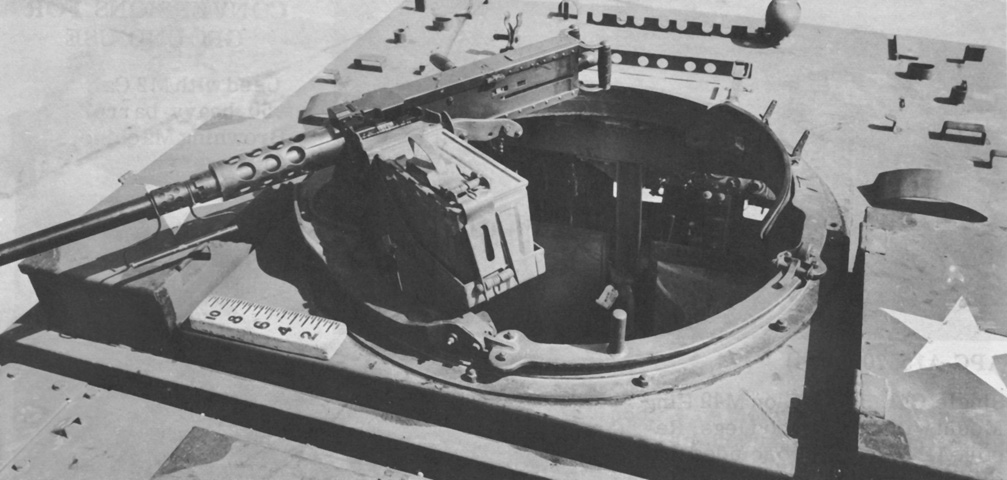
A .50cal machine gun M2HB is shown on a ring mount M49C. The ring mounts M49A1C or M66 could also be used. The M49A1C added a a deflector shield and a skate-type backrest for the gunner, and substituted a different carriage with a connecting stabilizer. The M66 was of roller bearing construction and the gun was traversed by rotating the inner ring. (Picture from TM 9-785 18-ton High Speed Tractors M4, M4A1, M4C, and M4A1C.)
The ring mount M49A1C is installed on this tractor. The gunner's backrest is opposite the gun carriage assembly, and the connecting stabilizer links the backrest and gun carriage. The connecting stabilizer also provides the gunner with a vertical handgrip for his left hand. (Picture from Weapon Mounts for Secondary Armament.)
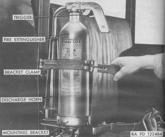
Two portable 4lb (1.8kg) CO2 fire extinguishers were carried, one in each cab compartment. (Picture from TM 9-785 18-ton High Speed Tractors M4, M4A1, M4C, and M4A1C.)
