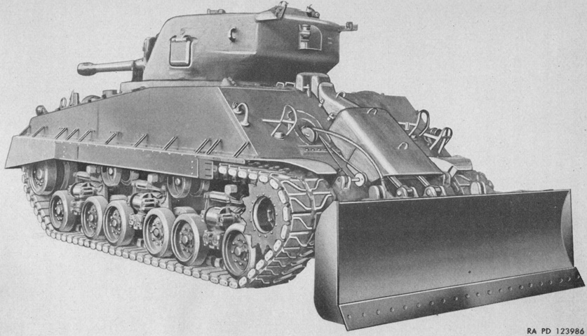
Tank-Mounting Bulldozer M2.
The M4A3(76)W HVSS Sherman's tank-mounting bulldozer M2 was converted in early 1945 from the design intended for high-speed tractors. In contrast to the tank mounting bulldozers M1 and M1A1, the M2 was not attached to the suspension units, which eased the task of mounting it to different vehicles. Including the required hydraulic oil, the unit increased the tank's weight by 6,000lb (2,700kg). With the bulldozer attached, the recommended top speed was 15mph (24kph), and the forward speed while bulldozing in low gear with the engine at 1,500rpm was 1-3mph (1.6-5kph). (Picture from TM 9-722 Tank-Mounting Bulldozer M2.)
The carrying position held the moldboard's cutting edge 29" (74cm) above the ground; the cutting edge was 30½'" (77.5cm) above the ground in its highest position and 12¼" (31.12cm) below ground level in its lowest position. The tank's angle of approach was 24° with the moldboard in its carrying position and 25° with it in the highest position. The moldboard's rate of lift was 5.83"/sec (14.8cm/sec) at 1,500 engine rpm, and 7.26"/sec (18.4cm/sec) at 2,600rpm. (Picture from TM 9-722 Tank-Mounting Bulldozer M2.)
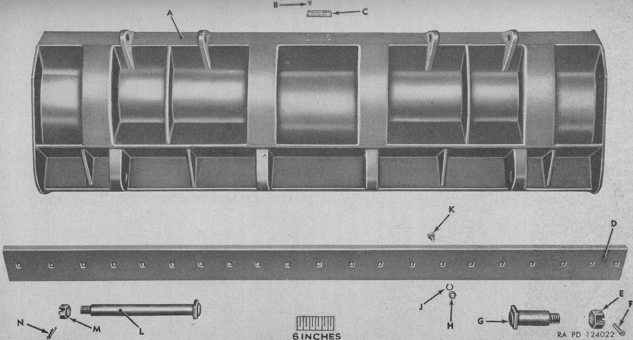
The moldboard and cutting edge are seen here from behind. The moldboard was 124" (315cm) wide and 36¾" (93.35cm) high, while the reversible cutting edge was 124" x 8¾" (315cm x 22.2cm). The cutting edge's angle with horizontal was 58° at the normal position and 65° in the lowest position. A. Moldboard. B. Screw, no.10 (0.190)-24NC-2 x½. C. Plate, name. D. Edge, cutting. F. Nut--1¾-10NC-3. G. Pin--8¼ x 2½. H. Nut--¾-10NC-2. J. Washer, lock--¾-inch (1.9cm). K. Bolt, plow--¾-10NC-2 x 2¾. L. Pin--20⅝ x 2. M. Nut--1½-12NF-3. N. Pin--⅜ x 2½. (Picture from TM 9-722 Tank-Mounting Bulldozer M2.)
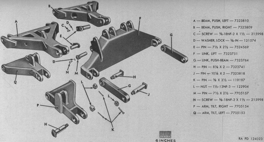
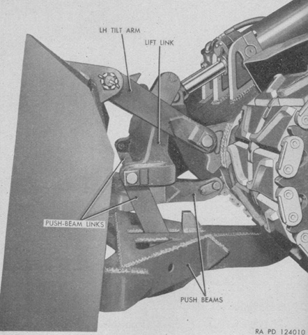
The lift link, push beams, tilt arms, and push-beam links that connected to the moldboard are shown in this exploded view. (Picture from TM 9-722 Tank-Mounting Bulldozer M2.)
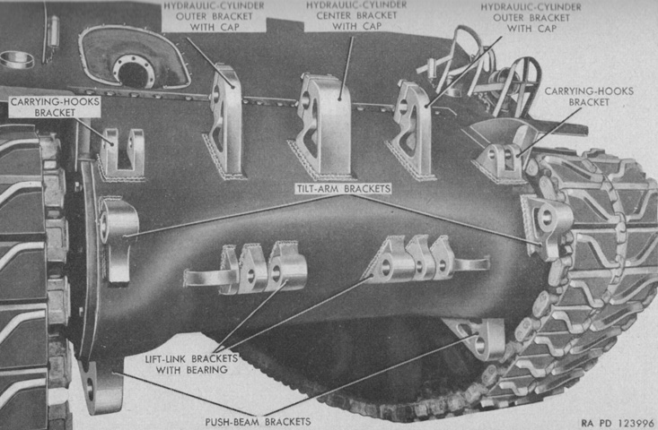
Before installation, interfering fixtures were removed from the hull front. These included the gun travel lock, tow cable clamp, front tie downs, front tow hooks, and bow machine gun and mount. Various brackets were then welded to the front hull. The tow hooks, travel lock, and tow cable bracket were reinstalled later. (Picture from TM 9-722 Tank-Mounting Bulldozer M2.)
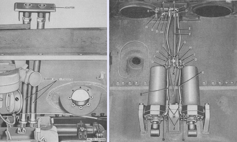
Two hydraulic cylinders were mounted on the hull front in order to control the moldboard. As seen on the left, the hydraulic fluid was supplied to the cylinders through hoses that used the assistant driver's hull periscope opening. The cylinders are installed on the right: A. 1 x 7" (2.5 x 18cm) pipe nipple. B. 1" (2.5cm) 90° elbow. C. Reducing Y fitting. D. 1 x 1½" (2.5 x 3.8cm) close-pipe fitting. E. Rubber hose. F. Hydraulic-cylinder inlet front pipe. G. Inlet-pipe tee clamp plate. H.¾" (1.9cm) union. J. 1 x¾" (2.5 x 1.9cm) reducing-pipe elbow. K. Mounting block. L. 1 x 1 x 1" (2.5 x 2.5 x 2.5cm) pipe tee. M. 1 x 5" (2.5 x 13cm) pipe nipple. N. 1 x 4" (2.5 x 10cm) pipe nipple. (Picture from TM 9-722 Tank-Mounting Bulldozer M2.)
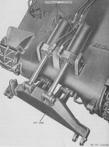
The lift link is installed and awaits connection to the moldboard. (Picture from TM 9-722 Tank-Mounting Bulldozer M2.)
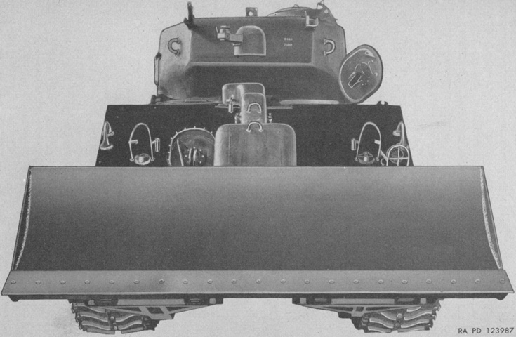
The moldboard is shown installed. (Picture from TM 9-722 Tank-Mounting Bulldozer M2.)
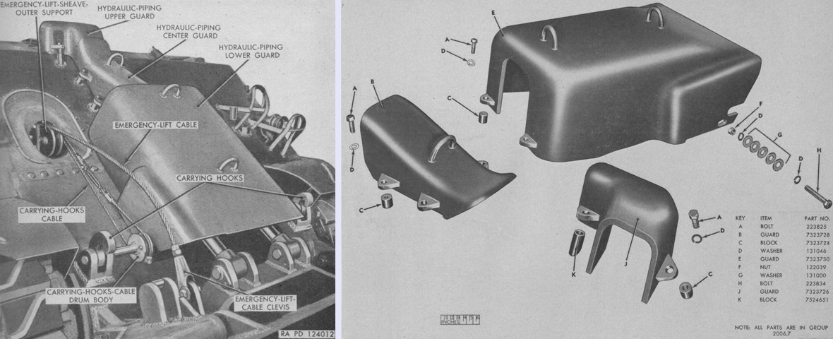
The emergency-lift cable and carrying hooks cable can be seen emanating from the bow machine gun aperture, and guards for the hydraulic cylinders and piping have been installed. The substantial hydraulic piping guards have been isolated on the right. (Picture from TM 9-722 Tank-Mounting Bulldozer M2 and ORD 9 SNL G-247 List of All Service Parts of Bulldozer, Tank-Mounting, M2.)
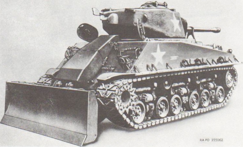
The bulldozer in this image has extra shielding for the hydraulics compared to the image above. (Picture from TM 9-2800-1/TO 19-75A-89 Military Vehicles (Ordnance Corps Responsibility).)
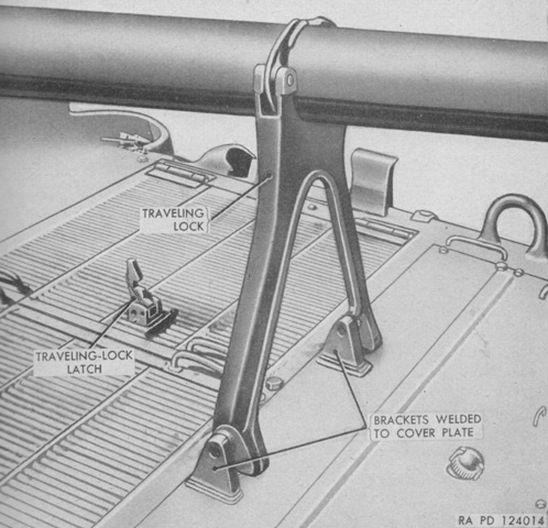
The gun travel lock was reinstalled on the rear deck, after cutting and grinding to ensure fitment to the less-sloped engine compartment plate. (Picture from TM 9-722 Tank-Mounting Bulldozer M2.)
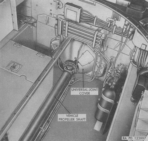
Inside, an hydraulic pump driven by the tank's main engine was installed at the rear of the turret compartment. It was necessary to remove all of the left-side floor plates above the stowage boxes, the rear stowage boxes on both sides, the support angle connected to the hull-floor center angle at the right rear corner of the ammunition box, the universal joint cover, the collector ring, the left floor support angle that extended through the center of the interior, the left-side sloping ammunition racks, and the right periscope mount and cover. The interior is shown here stripped down for installation; all parts except the periscope mount and cover and stowage boxes would be reinstalled once the hydraulic equipment was fitted. (Picture from TM 9-722 Tank-Mounting Bulldozer M2.)
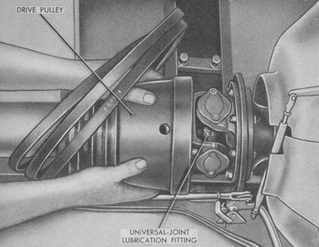
A drive pulley for the hydraulic pump was inserted over the rear end of the propeller shaft, and secured with eight 1⅝" (4.128cm) shoulder bolts and castle nuts and lock wires. (Picture from TM 9-722 Tank-Mounting Bulldozer M2.)
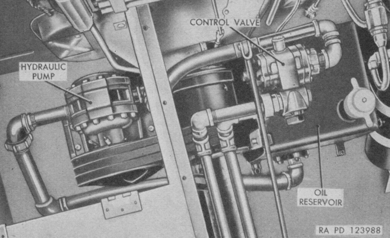
The hydraulic pump and is shown here after installation with the three drive belts in place. (Picture from TM 9-722 Tank-Mounting Bulldozer M2.)
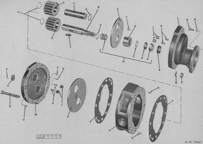
An exploded view of the hydraulic pump is diagrammed in this image. A. Ring. B. Gear. C. Shaft. D. Shaft. E. Plate. F. Dowel. G. Bearing. H. Seal, assy. 1. Spring. 2. Ring. 3. Seal. 4. Retainer. J. Plunger. K. Spring. L. Cover. M. Screw. N. Washer. P. Nut. Q. Washer. R. Seat. S. Key. T. Gasket. U. Dowel. V. Housing. W. Cover. X. Screw. Y. Plate. Z. Screw. (Picture from ORD 9 SNL G-247 List of All Service Parts of Bulldozer, Tank-Mounting, M2.)
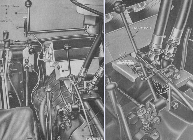
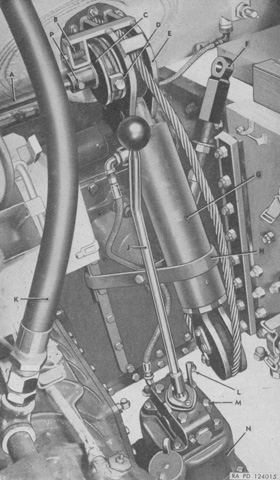
The interior controls are labeled in this image. The control-valve operating lever could be placed in four positions. From front to rear, these were FLOAT, DOWN, HOLD, and RAISE. DOWN and RAISE would move the moldboard in the selected direction. HOLD would keep the moldboard at the position it was currently in, while FLOAT allowed the moldboard to be moved by external forces. If it was in the air when FLOAT was selected, it would slowly settle onto the ground due to its weight. Locks secured the lever in the FLOAT or HOLD positions, as seen on the right. The hand-control shaft lever engaged or disengaged the carrying hooks that secured the moldboard in its elevated position for travel.
A. Decalomania. B. Hand-control shaft. C. Hand-control shaft bracket. D. Control-valve operating lever. E. Control-valve operating-lever instruction plate. F. Control-valve operating-lever bracket. G. Hydraulic-cylinder inlet and outlet rear pipes. H. Control rod. (Picture from TM 9-722 Tank-Mounting Bulldozer M2.)
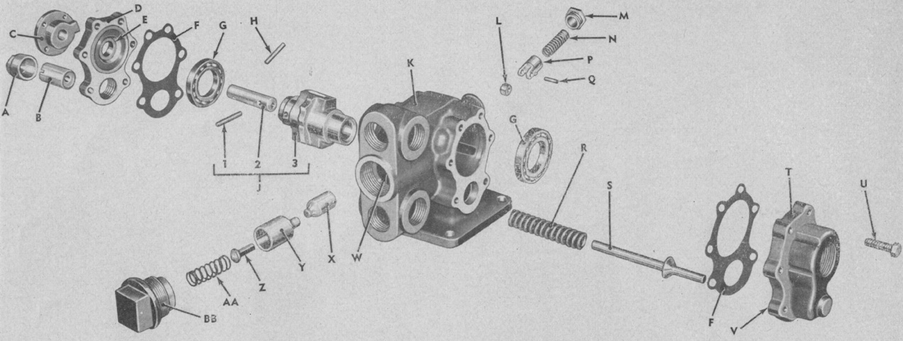
The inner workings of the control valve are revealed in this image. A. Cap. B. Screw. C. Head. D. Head. E. Seal (inside). F. Gasket. G. Bearing. H. Pin. J. Rotor, assy. 1. Pin. 2. Shaft. 3. Rotor. K. Body. L. Roller. M. Cap. N. Spring. P. Plunger. Q. Pin. R. Spring. S. Valve. T. Head. U. Screw. V. Seat (inside). W. Seat (inside). X. Pusher. X. Valve. Z. Valve. AA. Spring. BB. Cap. (Picture from ORD 9 SNL G-247 List of All Service Parts of Bulldozer, Tank-Mounting, M2.)
An emergency-lift jack was installed in the assistant driver's position to raise the moldboard in case of hydraulic failure, and its components are labeled here. The jack was operated by a hand-operated pump: moving the pump handle back and forth raised the jack, which would eventually place the moldboard in its extreme elevated position so that the carrying hooks could be engaged.
A. Hand-control shaft. B. Hand-control-shaft cable drum pin with compression spring. C. Carry-hooks cable drum. D. Carrying-hooks cable drug-block. E. Emergency-lift sheave inner support. F. Emergency-lift cable connector (anchor end). G. Moldboard-lifting emergency-lift jack. H. Emergency-lift jack support bracket. J. Emergency-lift pump operating lever. K. Rubber hose. L. Emergency-lift pump release-valve lever. M. Emergency-lift pump oil-reservoir filler plug. N. Emergency-lift pump. P. Cable drum hand-control shaft pin. (Picture from TM 9-722 Tank-Mounting Bulldozer M2.)
