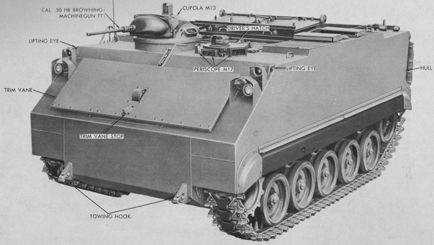
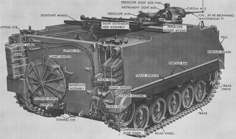
4.2" Self-propelled Mortar M84.
From the front, the M84 was visually quite similar to the armored personnel carrier M59 whence it was derived. (Picture from TM 9-2300-203-12.)
The trim vane is deployed, allowing a view of the hatch on the hull front that allowed access to the differential. The machine gun barrel is a replica.
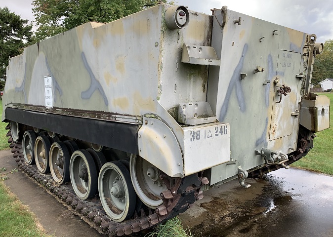
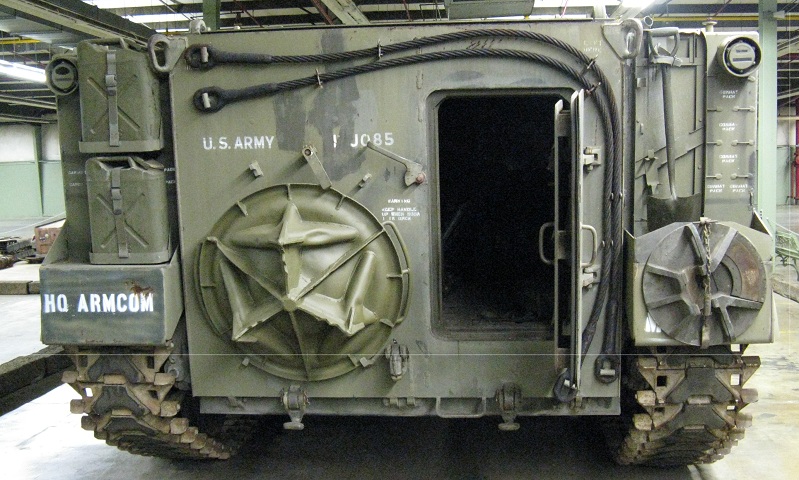
The door in the rear ramp of the M84 was relocated from the more central position found in the M59.
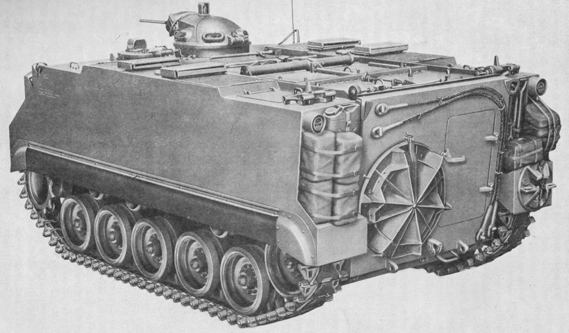
The large mortar baseplate assembly is seen stowed on the rear ramp opposite the door. Towing cables were also stowed on the rear ramp, while the mortar rotator assembly was kept on the vehicle's right rear fender. (Picture from TM 9-2300-203-12.)
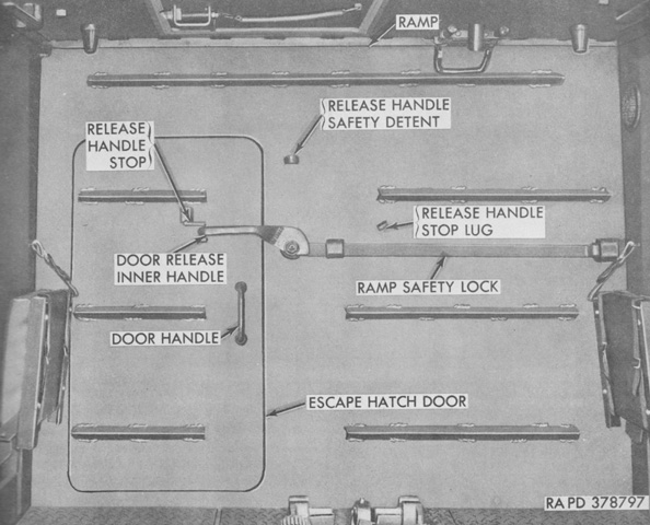
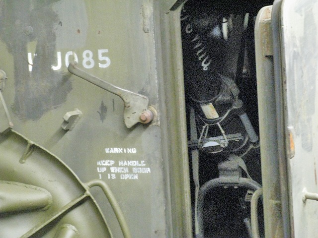
The internal controls for the offset door in the rear ramp are labeled in this image. (Picture from TM 9-2300-203-12.)
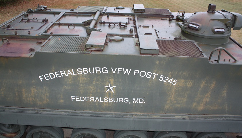
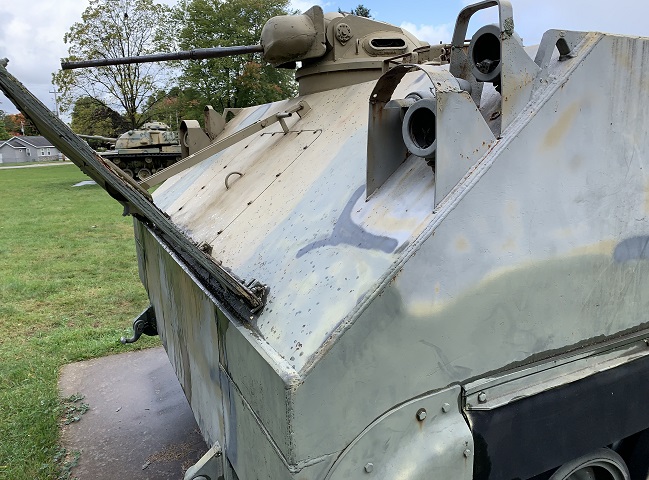
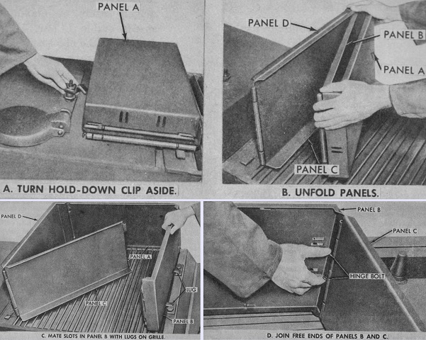
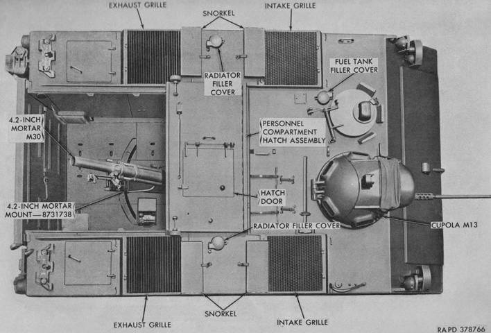
The central roof hatches in the M84 were modified from those found in the M59, and the new three-piece roof hatch is shown here. A torsion spring was mounted between the front and middle hatches, and small doors were placed in the front and rear hatches. The rear and center hatches were folded onto the front hatch to provide an opening through which to fire the mortar. This vehicle is armed with the M13 machine gun cupola, and on each side of the vehicle a front intake grille and rear exhaust grille can be seen for the engines. Snorkels for the grilles are stowed in the boxes on top of them, and the armored guard for the radiator filler caps are visible between the intake and exhaust grilles. An antenna aperture and guard is directly in front of the right-hand intake grille. (Photo by Richard S. Eshleman.)
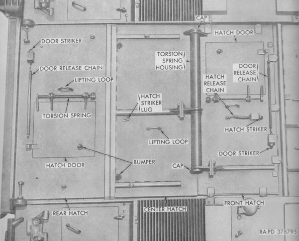
Further details and nomenclature of the roof is provided here. (Picture from TM 9-2300-203-12.)
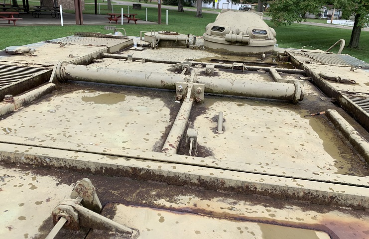
A closer view of the center roof hatch section and the torsion spring connecting it to the front section is provided in this image. The door in the rear section is on the right of the vehicle, while the front section's door is on the left. The snorkels are absent on this machine.
The snorkels on the M84 protected the air intake and exhaust grilles when swimming. (Picture from TM 9-2300-203-12.)
A smaller mortar baseplate and a rotator assembly are stowed on this machine, and the rear door is ajar. Note the cross-section of the door.
The 4.2" mortar M30 can be seen through the rear door. It was situated in the vehicle facing the rear, and the roof hatches could be folded on top of each other to the front of the vehicle to allow firing without dismounting the ordnance.
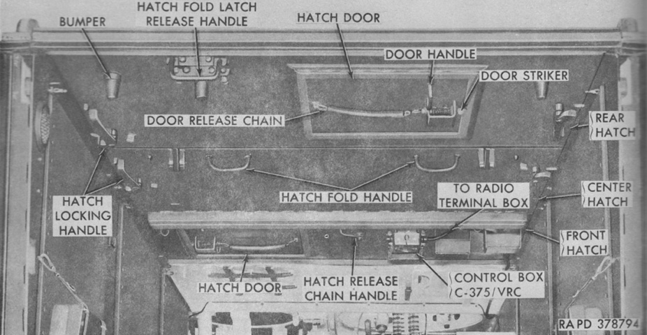
The controls for the folding roof hatches and the roof hatch doors are labeled here with the ramp lowered. (Picture from TM 9-2300-203-12.)
The roof hatches are shown folded forward. (Picture from TM 9-2300-203-12.)
The rear compartment roof has been folded forward, allowing a view of the mortar and its traversing quadrant. (Picture from TM 9-2300-203-12.)
The roof hatches have been folded forward and the rear ramp has been lowered, allowing a better view of the interior. (Picture from TM 9-2300-203-12.)
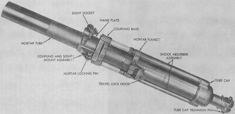
The muzzleloading 4.2" (107mm) mortar M30 was rifled and could be dismounted from the vehicle for use with the mount M24A1. The tube cap closed the tube and housed the ordnance's integral firing pin. The tube cap trunnion pin locked the mortar into the bridge assembly. Two shock absorber assemblies helped absorb recoil forces. (Picture from TM 9-2300-203-12.)
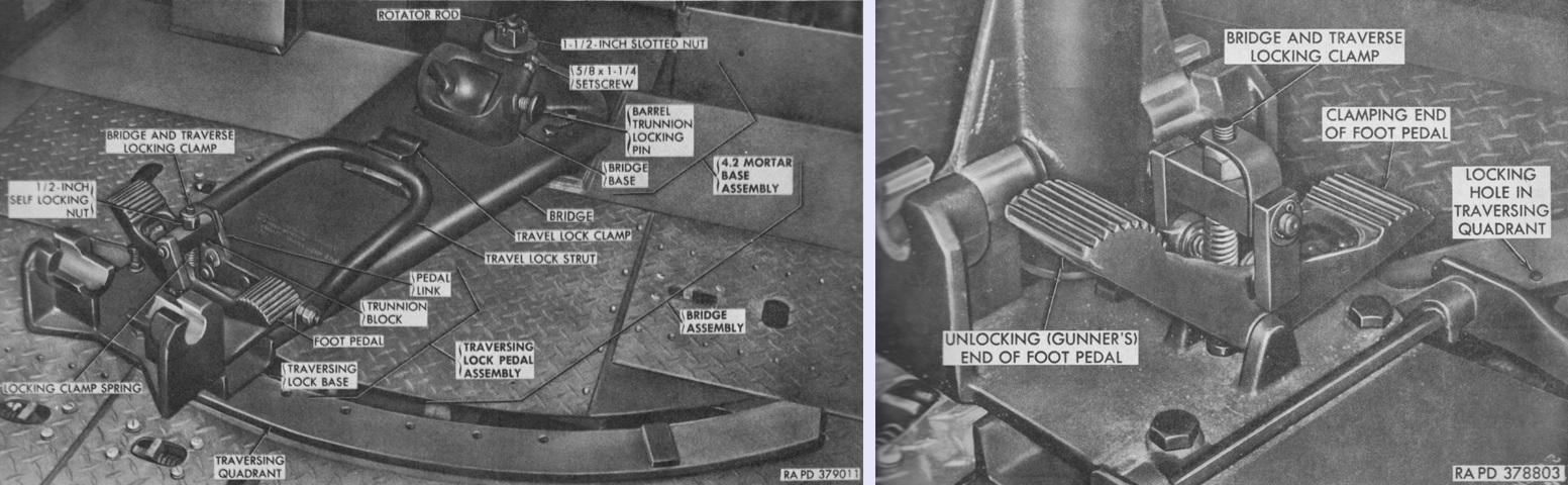
The mortar bridge and traversing quadrant are highlighted in the left image with the mortar absent. The quadrant was bolted to support beams in the hull floor, and had seven locking holes spaced at 107-mil intervals, providing a total traversing arc of 642 mils. The foot pedals allowed the mortar base to be locked into the holes of the traversing quadrant. The left pedal unlocked the clamp, while the opposite side locked it into place in one of the holes. The pedal was spring loaded so that the left pedal had to be held open in order to move the mortar; when released the pedal automatically returned to the normal locked position. The barrel trunnion locking pin was a two-position detent pin that secured the mortar tube cap in the socket. The traverse lock foot pedals are isolated on the right. (Picture from TM 9-2300-203-12.)
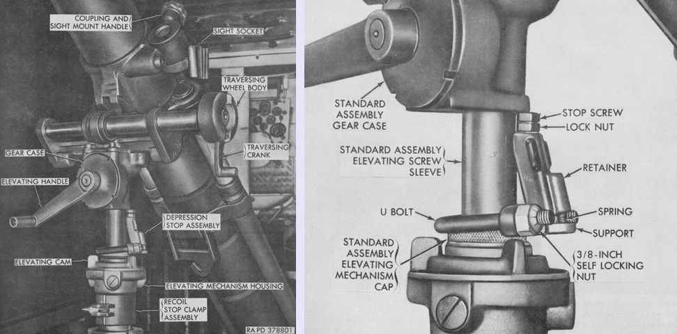
Details of the mortar controls are illustrated on the left. The elevating cam could be turned 90° clockwise to unlock the screw housing, allowing the mortar to be placed in its raised or lowered position. In the lowered position, using the elevating handle provided 800 to 933 mils of elevation, and when raised the elevating mechanism provided from 919 to 1,045 mils of elevation. The traversing crank could be unfolded from the traversing wheel body to provide coarse adjustments, while fine adjustment was made by turning the traversing wheel body itself. A total of 240 mils of traverse was capable with the mount.
The depression stop assembly is highlighted on the right. It was mounted on top of the elevating cap, and prevented the mortar from being depressed below the minimum elevation for safe firing from the vehicle. It consisted primarily of a stop screw, a retainer, a spring, a U-bolt, and a support. It was to be installed and adjusted whenever the mortar was to be fired while mounted. When the vehicle was emplaced, the average longitudinal cant was determined by placing the gunner's quadrant M1A1 on top of each engine compartment and then averaging the values. Eight hundred mils were added to this average to determine the minimum elevation. The mortar was elevated to this value, and the depression stop was then installed and the stop screw was turned until it touched the bottom of the standard assembly gear case. The lock nut was then tightened against the stop screw. The depression stop assembly was removed when the mortar was stowed for travel or used from the ground mount M24A1. (Picture from TM 9-2300-203-12.)
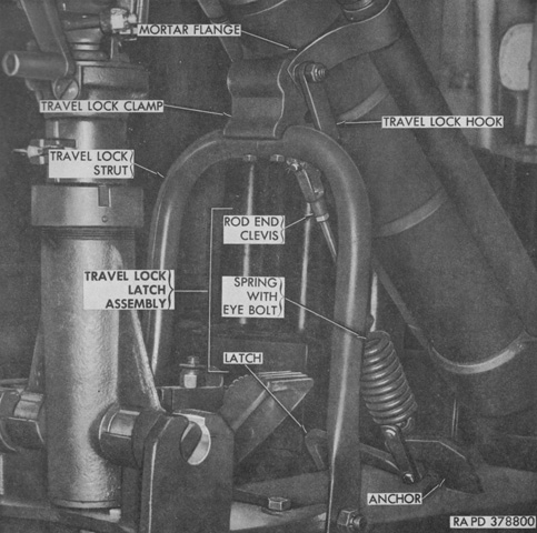
When moving, the rod end clevis on the travel lock latch assembly was attached to the travel lock hook on the mortar flange, and the latch on the other end of the latch assembly was connected to the anchor on the mortar bridge assembly. (Picture from TM 9-2300-203-12.)
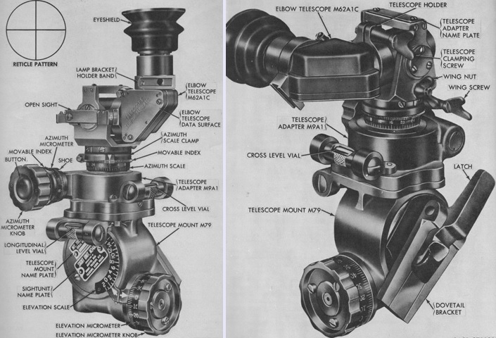
The sightunit M34A2 was used to lay the mortar in both azimuth and elevation. It was composed of the elbow telescope M62A1C, the telescope adapter M9A1, the telescope mount M79, and a cross level vial. The M62A1C was a fixed-focus monocular telescope with 3x magnification and a 12°12' field of view. The M62A1C could be rotated in its holder to permit observation from above or from the side of the sightunit. The M9A1 contained an azimuth micrometer knob that provided 6,400-mil rotation of the telescope. The sprung button in the middle of the knob disengaged the knob from the azimuth micrometer so that the micrometer could be slipped in azimuth. The M79 contained a worm gear mechanism that was actuated by the elevation micrometer knob to provide 1,800 mils of elevation. (Picture from TM 9-2300-203-12.)
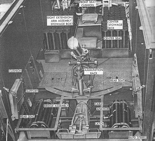
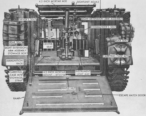
Ammunition stowage and the mortar crew seats can be seen in this image. With the rear floor sections removed, the torsion bars can also be seen running across the hull bottom. (Picture from TM 9-2300-203-12.)
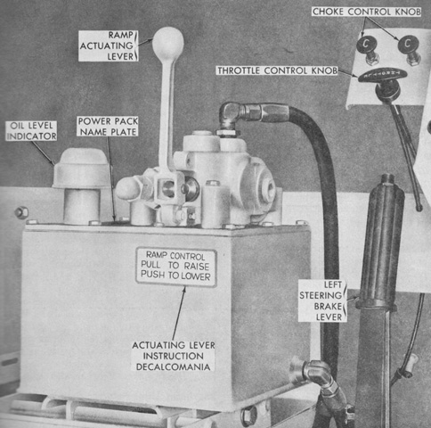
The ramp hydraulic power pack in the M84 differed from that found in the M59. When the lever was pushed forward, the ramp lowered, and vice-versa. The lever returned to neutral when released. Pushing the lever farther in either direction increased the speed with which the ramp raised or lowered. (Picture from TM 9-2300-203-12.)
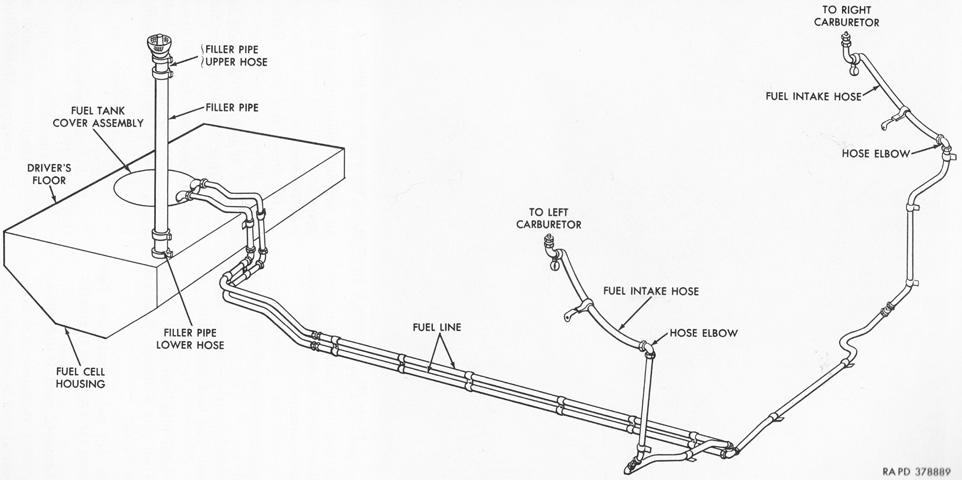
The fuel lines on the M84 were forced to one side due to the installation of the mortar mount. (Picture from TM 9-2300-203-12.)
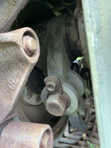
The eccentric aluminum idler adjusting arm is shown here, which allowed track tension to be adjusted. This was accomplished by first loosening the small clamping bolt until the lock plate through which it was threaded could be turned, freeing the large adjusting nut just below, which was attached to the idler adjusting arm. Loosening the adjusting nut decreased track tension, and tightening the adjusting nut increased track tension. The target tension was confirmed by the top of the track sagging .75-1" (1.9-2.5cm) below the center of a straightedge measured halfway between the hubs of the center and rear track support rollers. The compensating idlers were attached to the rear road wheels via linkages so that upward movement of the rear road wheel arms forced the adjusting and idler arms to turn as one and extend the idler wheels to the rear and thereby take up excess track slack.
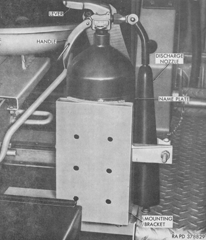
In contrast to the M59, which mounted its portable fire extinguisher horizontally on the floor behind the driver, the M84 secured it vertically with a bracket to the right rear of the driver's seat, which can be seen in the background. (Picture from TM 9-2300-203-12.)
