120mm Self-propelled Mortar Carrier M1064.
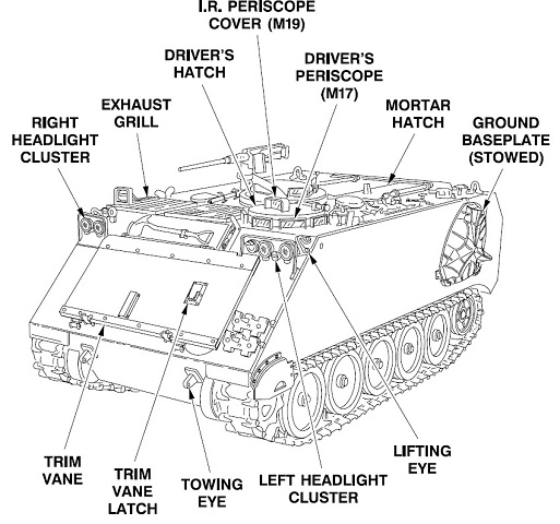
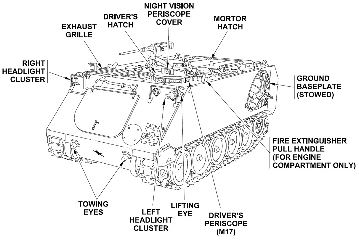
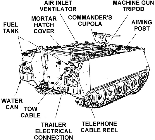
Details of the front of the vehicle are sketched here. (Picture from TM 9-2350-261-10.)
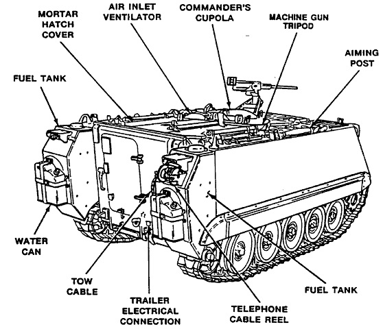
This illustration reveals rear stowage and the fuel tanks. (Picture from TM 9-2350-261-10.)
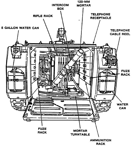
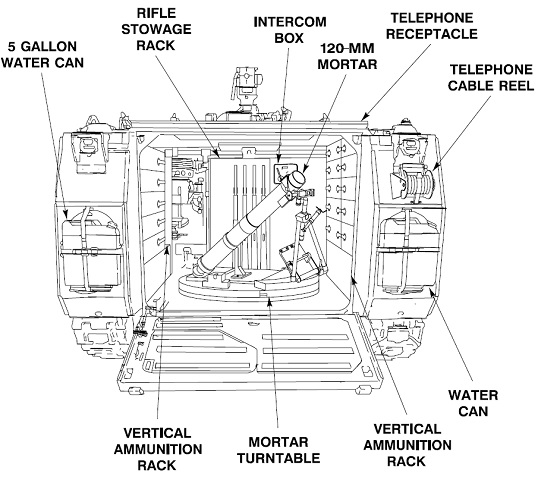
The stowed mortar and interior stowage are shown here. (Picture from TM 9-2350-261-10.)
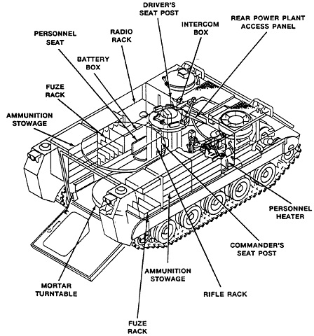
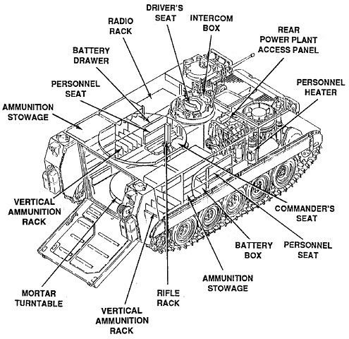
Further interior details are drawn here. (Picture from TM 9-2350-261-10.)
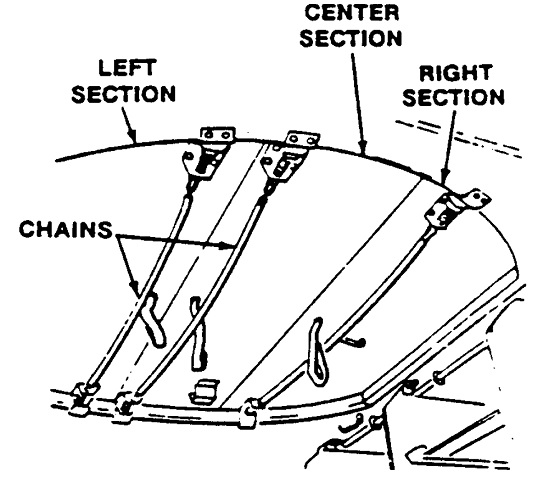
In order to open the mortar hatch, the commander's cupola first had to be traversed to the side. Then the interior catches were released by pulling on the chains. The center section was first folded and locked onto the right section, then both were opened onto the top deck. The left section was then pushed up onto the deck. To close the hatch, the outside catches were released by turning their interior handles, and the straps attached to the inside of the hatch sections were used to pull the sections shut. (Picture from TM 9-2350-261-10.)
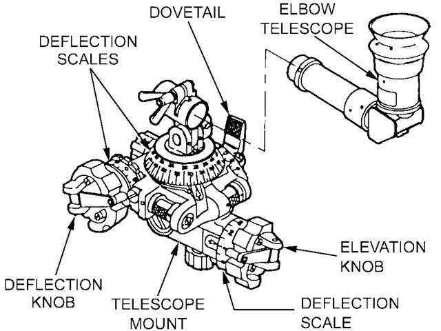
The sightunit M67 was composed of an elbow telescope and a telescope mount. The telescope had a 10° field of view with 4.0x nominal and 3.5x effective magnification. Illumination was provided by a tritium vial with a service life of 6-8 years. It was 4⅜" (11.11cm) x 5⅜" (13.65cm) x 8½" (22cm) and weighed 2.9lb (1.3kg). (Picture from FM 23-90 C1 Mortars.)
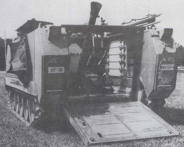
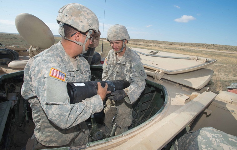
The folding roof hatch on this M1064 is open and the 120mm mortar is deployed; the external fuel tanks are fitted on the vehicle rear as well. The hatch folds open, with one section opening to the left and two sections folding to the right. Ammunition and fuze stowage is visible on the right side of the compartment. (Picture from TM 55-2350-224-14.)
Externally, the M1064A3 was very similar to the M1064. (Picture from TM 9-2350-277-10.)
This illustration reveals rear stowage and the fuel tanks. (Picture from TM 9-2350-277-10.)
Changes to the driver's controls have occurred from the earlier version. (Picture from TM 9-2350-277-10.)
Internal stowage is sketched in this diagram. (Picture from TM 9-2350-277-10.)
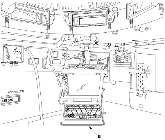
The mortar fire control system (MFCS) M95 was comprised of a commander's interface, gunner's and driver's displays, pointing device, a vehicle motion sensor, and a power distribution assembly that protected against reverse polarity and power surges or fluctuations. In this image, the commander's interface is "a," and it manages the information flow between the vehicle and the fire direction center, interfaces other MFCS components and the vehicle radios, computes fire control solutions, and uses a Microsoft Windows-type interface to provide the commander with text and graphics. (Picture from TM 9-2350-277-10.)
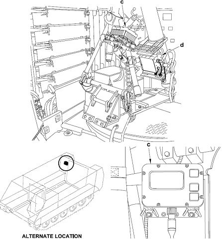
The gunner's display (c) relays information for the gunner to aim and fire the mortar, including deflection and elevation orders, and it also has check fire and call for fire capability. The pointing device (d) maintains the alignment of the mortar within 3 mils of azimuth and 1 mil of elevation, and has an operating range of 80°S to 84°N latitudes. (Picture from TM 9-2350-277-10.)
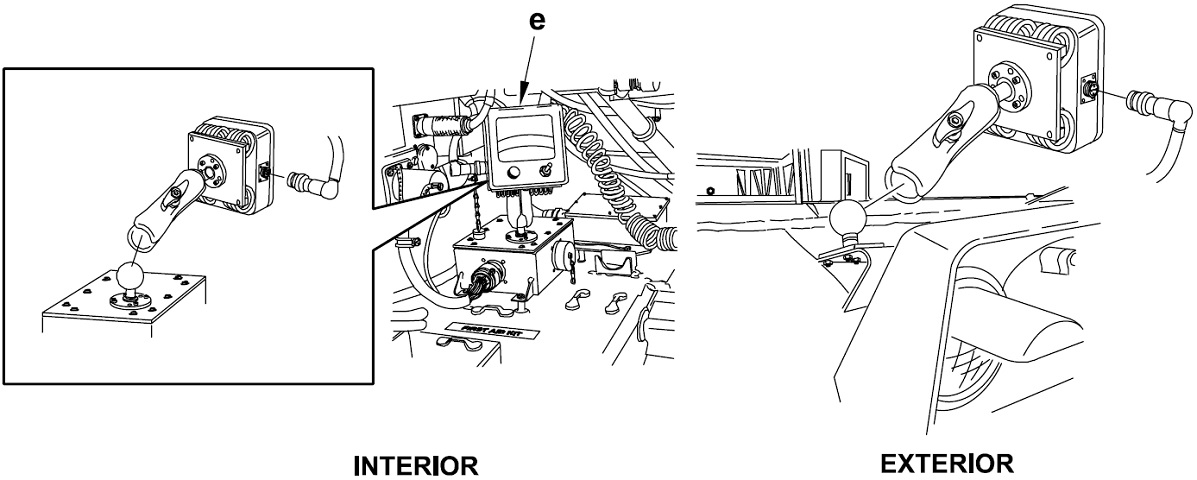
The driver's display (e) gives the driver information required to orient the vehicle during emplacement and when driving to the next coordinates. Steering directions and compass orientation are provided in graphical form, while distance and heading are via numerical readouts. (Picture from TM 9-2350-277-10.)
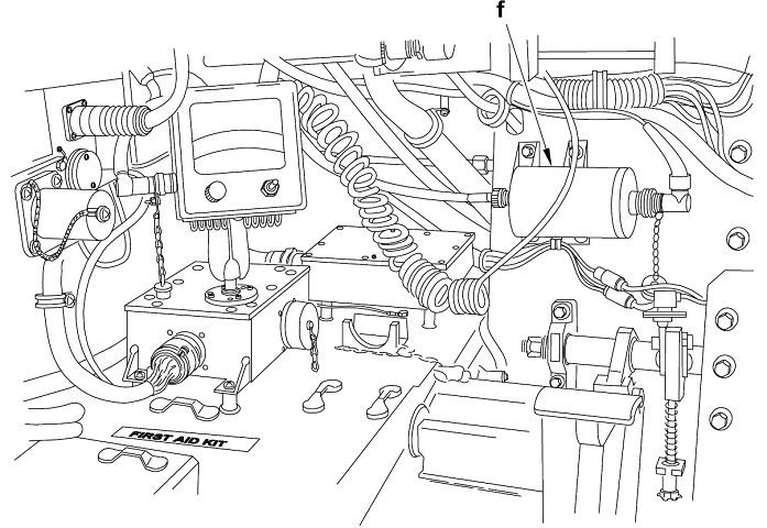
The motion sensor (f) is attached inline to the vehicle's odometer, and it gives the pointing device data required to lessen vertical position error. (Picture from TM 9-2350-277-10.)
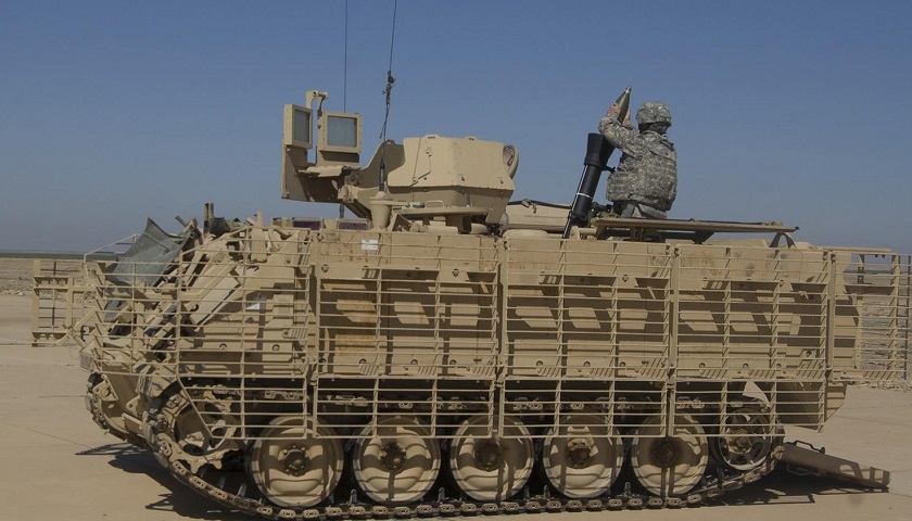
This vehicle has been fitted with slat armor to help defend against antitank rockets, and the commander has been provided with armored shields around his cupola; note that the machine gun is not mounted, however. The roof hatches and the rear ramp are open. (Picture taken 17 Mar 2011 by SPC Terence Ewings; available from the Defense Video & Imagery Distribution System.)
Details of the folding roof hatches, including the opening chains and hand straps, can be seen in this image. The hatch for the commander's cupola is open towards the front of the vehicle; the open driver's hatch can be glimpsed to the extreme front, and the rear ramp to the lower right of the image is also open with another soldier standing on it. There is an air inlet ventilator on the hull roof between the commander's cupola and the open roof hatch. Ammunition stowage can be seen inside the vehicle. (Picture taken 21 Aug 2014 by by MAJ Wayne Clyne; available from the Defense Video & Imagery Distribution System.)
