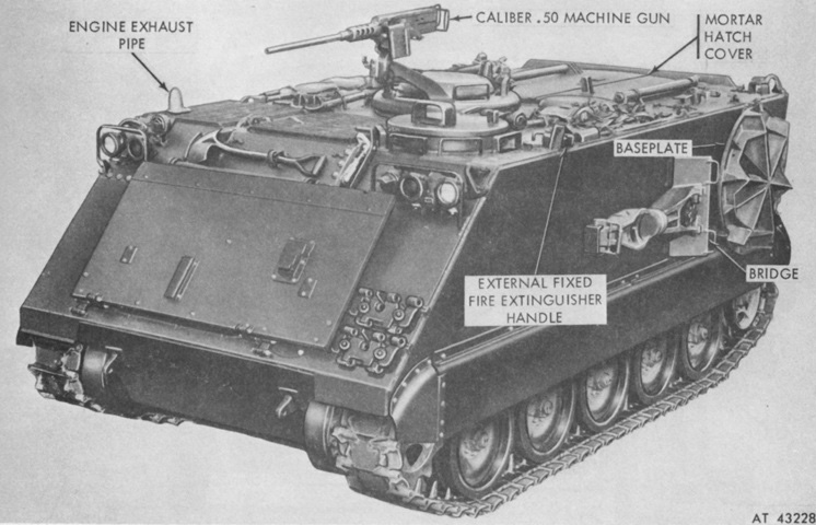
107mm Self-propelled Mortar Carrier M106.

The side-mounted stowage for the mortar bridge and baseplate are illustrated in this picture, and the hinged mortar hatch cover can also be seen. (Picture from TM 9-2300-224-10.)
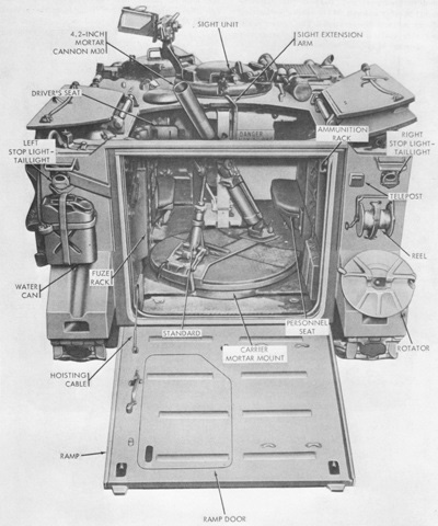
The mortar is ready for use in this picture; although the ramp was normally closed during firing it could be opened if the tactical situation permitted. The right-side portion of the roof hatch was made up of two folding sections, and the left of a single section. Stowage for the ground mount rotator was on the right rear fender. There was a horizontal rack for mortar ammunition on the right that stowed 63 bombs, and a vertical rack on the left that stowed 30 bombs. Sixty-three fuzes were carried: 56 in the fuze rack on the left and seven in two canisters in the right forward ammunition rack. In contrast to the M113 on which it was based, the M106 stowed its portable fire extinguisher on the left rear corner of the rear compartment. (Picture from TM 9-2300-224-10.)
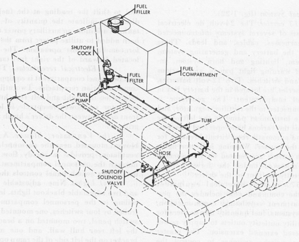
Instead of the M113's diagonal routing, the fuel line in the mortar carrier kept to the left-hand wall in deference to the placement of the mortar mount. (Picture from TM 9-2300-224-10.)
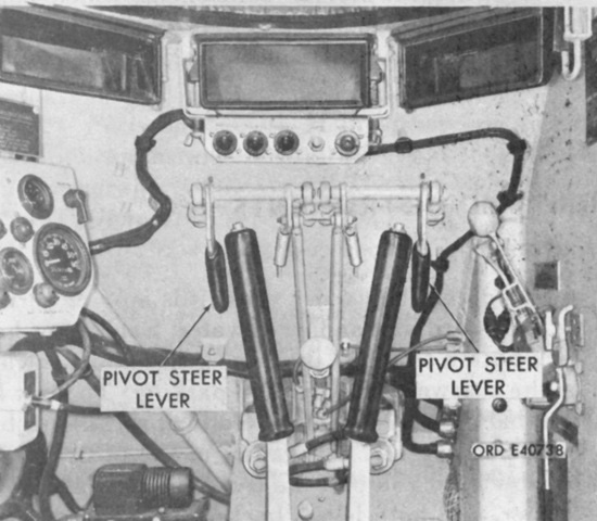
The driver was provided with two pivot steer levers in addition to the normal steering levers. These were primarily intended for the short-radius turns needed when positioning the carrier before firing, but they could also be used for emergency stops and were to be used for steering while afloat. The transmission shift lever was to be in ranges 1 or 2 and the carrier at 15mph (24kph) or below when using the pivot steer levers. Unlike the steering levers, where the degree of actuation determined the sharpness of the turn, the pivot steer levers were always intended to be applied fully. (Picture from TM 9-2300-224-10.)
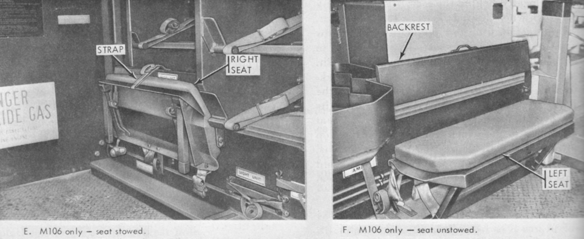
The two personnel seats were at the front corners of the mortar compartment. The seats could be stowed as shown in the left image, and the backrests could be folded forward to access the battery box behind the left seat and the ammunition rack behind the right seat. (Picture from TM 9-2300-224-10.)
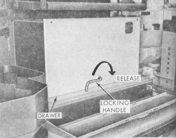
The battery box of the mortar carrier was in the left sponson behind the personnel seat backrest. The batteries were contained in a drawer that could be pulled out of the box. (Picture from TM 9-2300-224-10.)

The revised roof hatch is detailed here. The commander's cupola needed to be rotated to the side before the mortar hatch could be opened or closed. Each section of the hatch was secured to the hull by two spring-loaded bolts that engaged strikes on the hull roof. The bolts were connected by a rubber-covered chain that could be pulled to disengage the bolts from the strikes. Each section also had a hold-open latch that could be released from inside by pulling a release handle in either direction. The center section was to be opened and secured in its hold-open latch first, and the center section was to remain latched to the right-hand section until the right-hand section was closed. (Picture from TM 9-2300-224-10.)
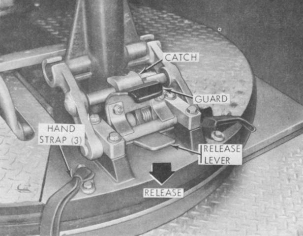
Located on the rear of the mortar turntable, the mortar standard assembly support secured the standard mortar assembly to the turntable. A hinge allowed it to be raised for firing or lowered for travel. A spring-loaded catch secured the support in the raised position after the mortar was lifted with a crewman's shoulder, and this could be released by stepping on the release lever. The labeled hand straps were used to traverse the turntable; two were at the turntable's rear and one at the front. (Picture from TM 9-2300-224-10.)
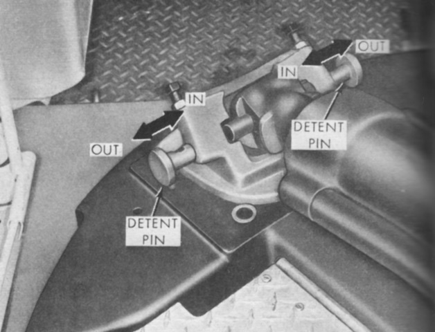
The mortar tube socket, opposite the standard assembly support, was used to secure the mortar tube cap to the turntable. A detent pin on each side was inserted to secure the tube cap, or pulled to the outer detent to insert or release the tube cap. (Picture from TM 9-2300-224-10.)
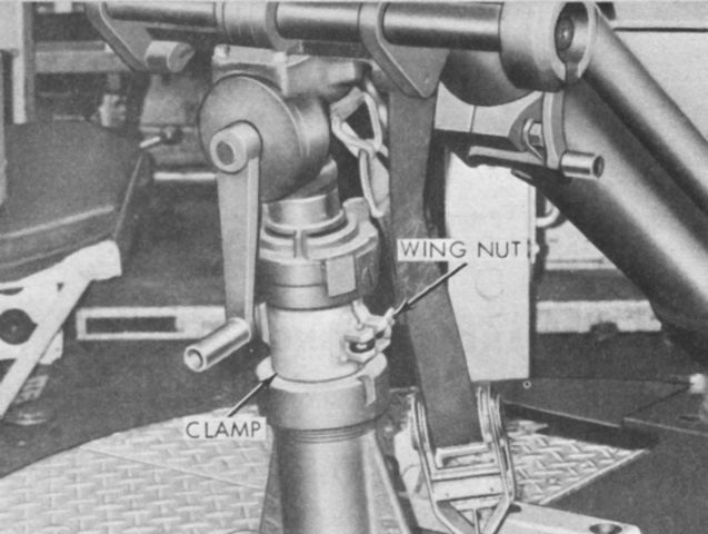
The recoil stop clamp was a hinged collar installed on the standard assembly recoil mechanism when the mortar was mounted in the carrier, and removed when firing from the ground mount. It prevented the mortar tube from being depressed or recoiled below safe firing limits. (Picture from TM 9-2300-224-10.)
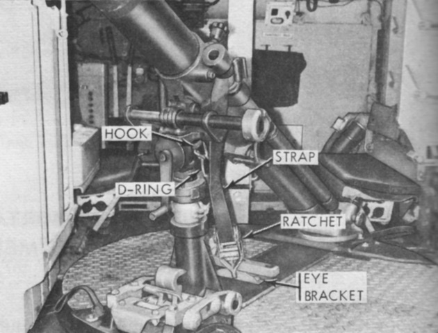
The mortar tiedown strap secured the mortar during travel by being looped around the mortar tube with the hook attached to the D-ring and the ratchet hooked to an eye in the turntable. Slack in the strap was then removed by the ratchet. (Picture from TM 9-2300-224-10.)
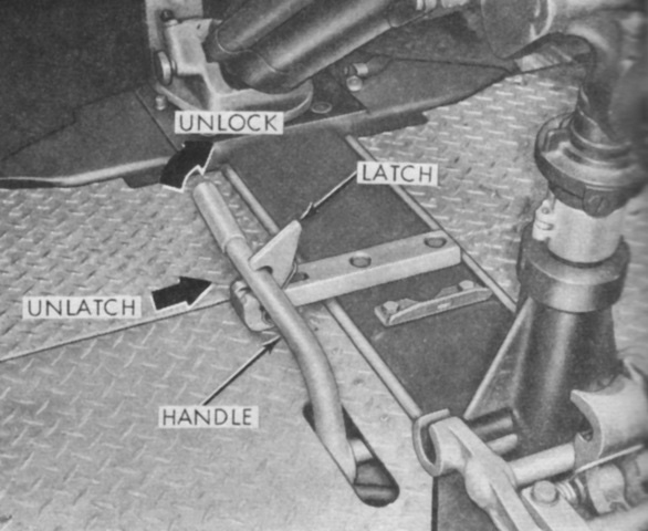
The traverse locking handle could secure the turntable at a desired azimuth by engaging the teeth of an indexing ring below the turntable. The handle was pushed downward until the spring-loaded locking latch snapped over the handle. To release the handle, the latch was pushed inward and the handle raised. (Picture from TM 9-2300-224-10.)
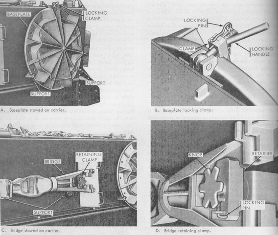
Controls for the stowage of the mortar baseplate and bridge are detailed in these images. The baseplate was secured by a locking clamp that was tightened with a locking handle that used a chain-attached locking pin to prevent backing off. The bridge used a retaining clamp with a spring-loaded locking pin to keep it in the supports on the hull side. (Picture from TM 9-2300-224-10.)
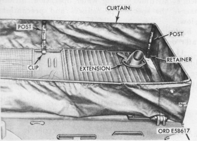
The mortar carrier was provided with a curtain to be placed around the air grilles when afloat. If the carrier was fully loaded with ammunition, fuzes, and the mortar ground mount components, the freeboard on each side would be equalized. If there were 60 or fewer mortar bombs aboard, they were to be divided evenly between each side of the carrier. If more than 60 rounds were present, the left-hand ammunition rack was to be completely filled first, with the right-hand rack accepting the remaining rounds. (Picture from TM 9-2300-224-10.)
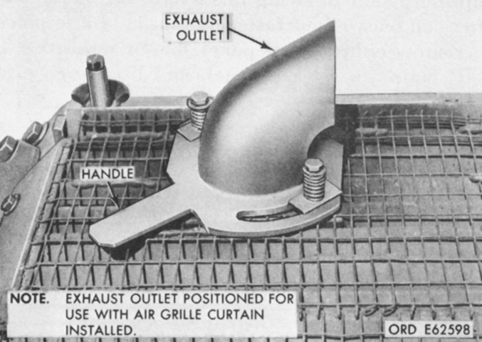
The exhaust extension for the mortar carrier could be swiveled with the attached handle. While normally pointed to the side, the outlet was to be turned to the rear when the air grille curtain was erected so that the exhaust did not damage the curtain. (Picture from TM 9-2300-224-10.)
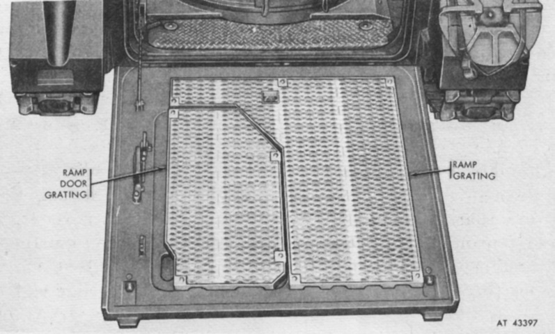
Nonskid grating could be installed on the rear ramp as part of the winterization kit. The ramp door had its own section of grating, and the door handle and stops were raised by spacers so that they would still be operable with the grating installed. (Picture from TM 9-2300-224-10.)
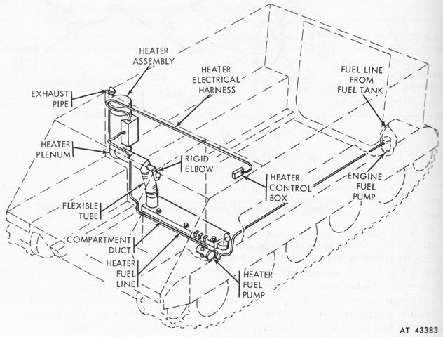
The fuel line for the personnel heater had to take a similar route as the engine fuel lines. (Picture from TM 9-2300-224-10.)
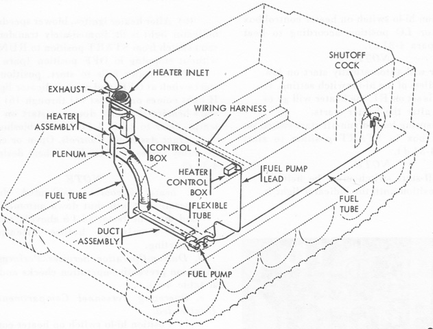
The M106A1's heater fuel lines followed a similar path. (Picture from TM 9-2300-257-10.)
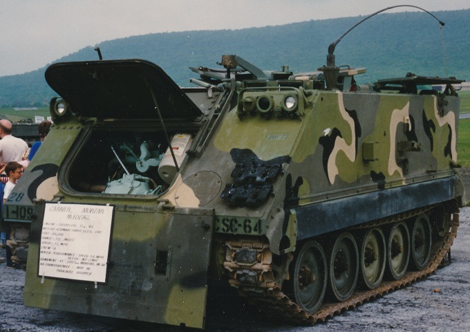
This M106A2 has its trim vane lowered and powerplant compartment front door opened. Stowage brackets for the mortar bridge and baseplate are attached to the left side of the hull. The engine's cylindrical air cleaner is visible closest to the driver, and the differential is low and forward in the engine compartment. This M106A2 is fitted with the T130E1 single-pin tracks. (Photo by Richard S. Eshleman.)
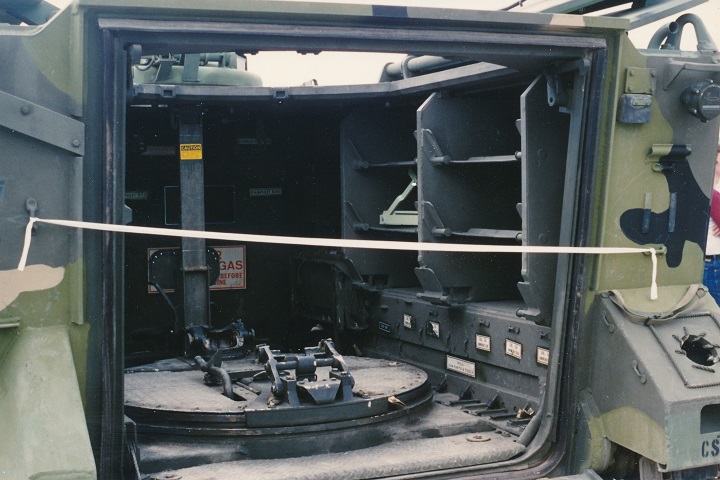
A view into the rear compartment allows us to see the mortar turntable with attachment points for the mortar itself. Ammunition stowage was provided in the sponsons over the tracks. The right rear fender could accept the mortar rotator assembly for travel, but like the bridge and baseplate on the side of the vehicle, it is not mounted here. (Photo by Richard S. Eshleman.)
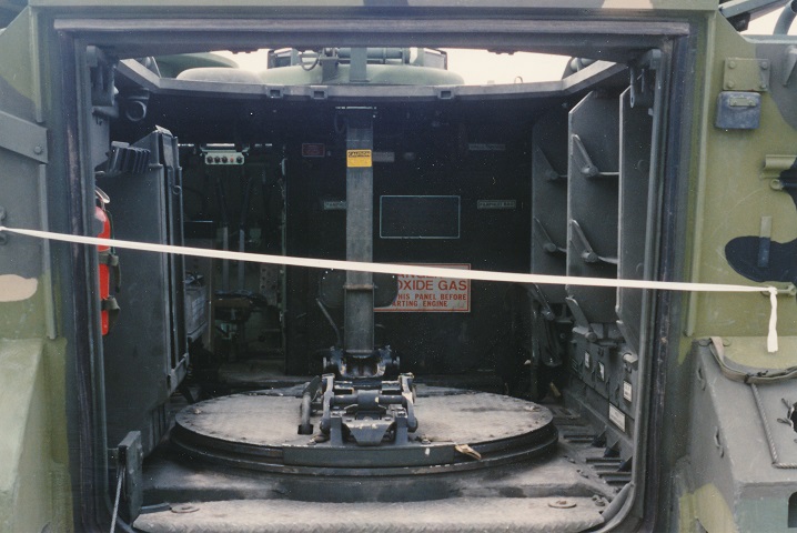
Another shot of the interior shows the driver's station to the front left, a fire extinguisher and rifle stowage clips in the left rear, and a rack for fuzes in front of the fire extinguisher. (Photo by Richard S. Eshleman.)
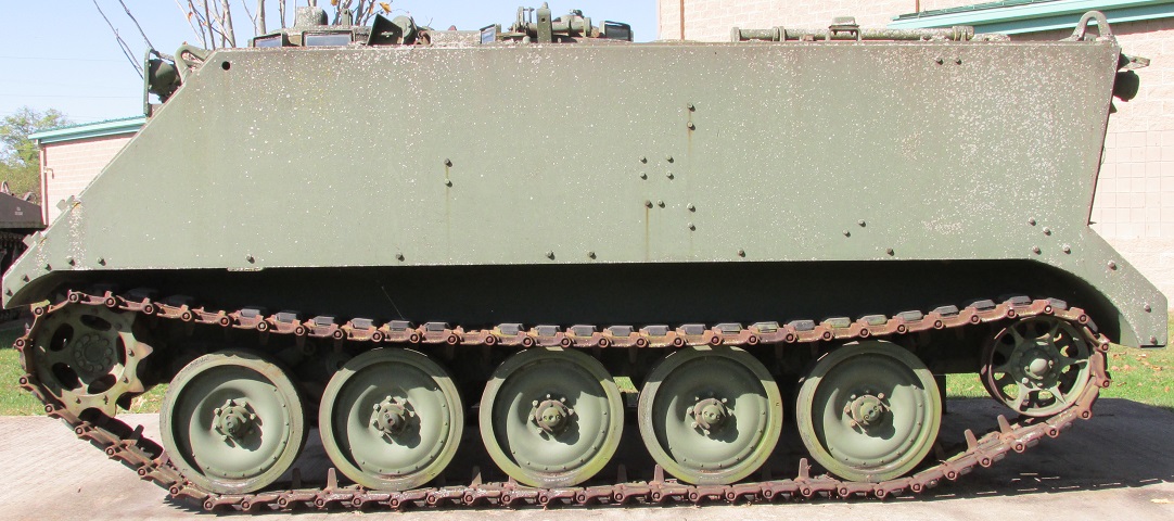
The mounting brackets for the mortar bridge and baseplate have been removed from this vehicle, but the bolts that attached the brackets to the hull remain, allowing a glimpse of their outline. The line of bolts along the bottom off the hull were to attach dust shields.
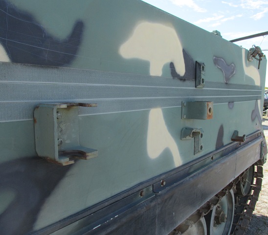
The mounting brackets and dust shield are present on this machine.
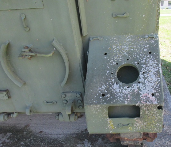
Similarly, the holes in the right rear fender for nylon cord are visible, but the cord itself is absent.
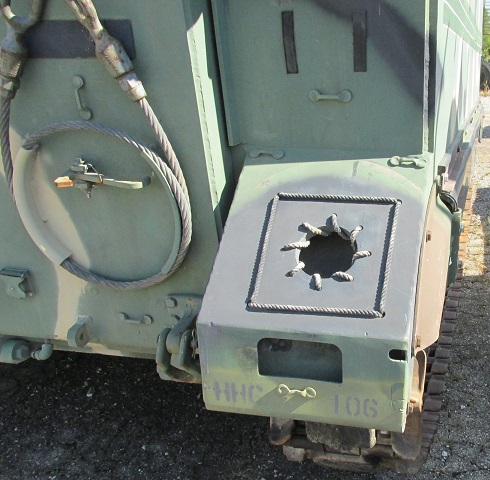
Details of the cord's weaving in the holes can be seen on this vehicle.
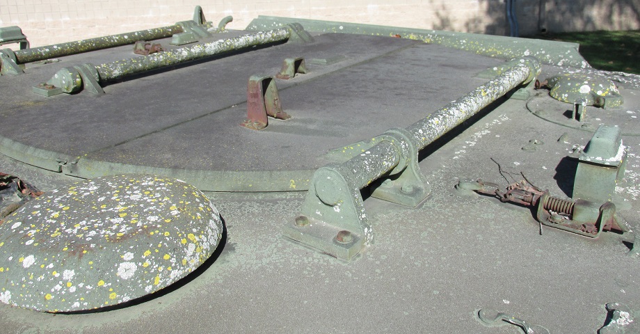
The roof hatch is illustrated here. The hatch had a circular profile to the front and rear, and the right-hand hatch had an additional hinge to fold in the middle. The passenger compartment ventilator intake was relocated to in front of the hatch.
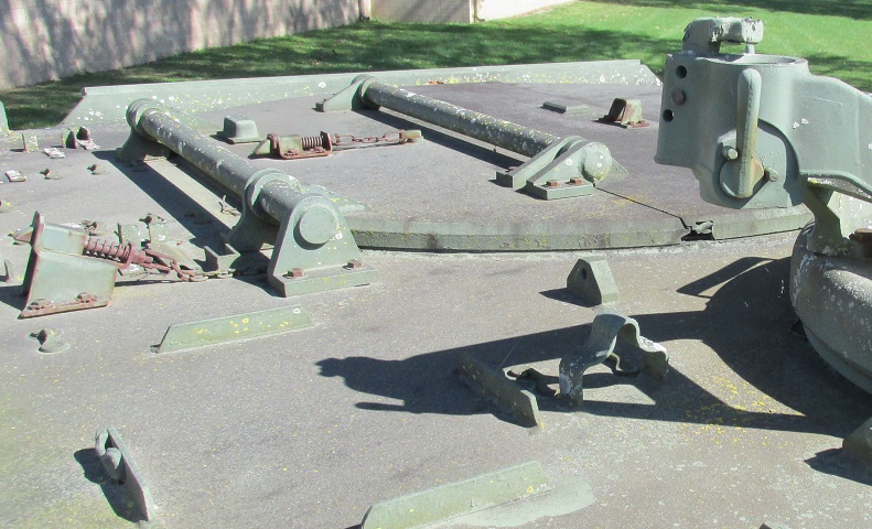
The opposite side of the roof hatch is visible in this picture. The hinge in the folding right-side roof hatch can be clearly seen. The socket for the .50cal cupola machine gun is in the foreground in front of the roof hatch.
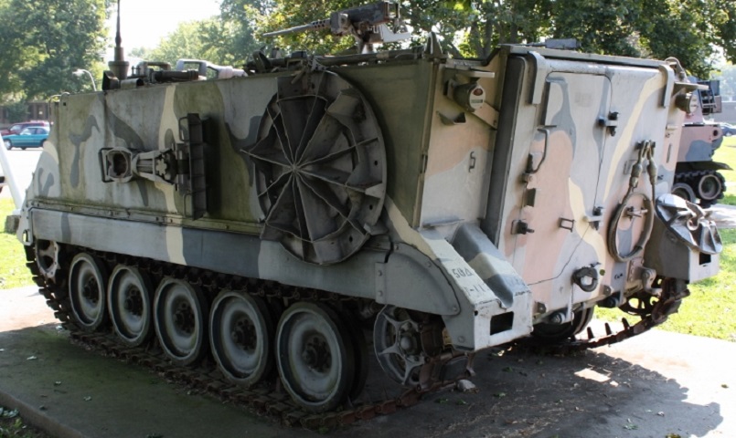
This vehicle sports the mortar equipment on the outside of the hull, and a tow cable is wound on the rear ramp. (Photo by Richard S. Eshleman.)