

| M20: General | |||
| Date of first acceptance | July 1943 | Total acceptances | 3,791 |
| Manufacturer | Ford Motor Co. | Crew | 6 men |
| M20: Dimensions | |||
| Combat weight | 15,650lbs 7,099kg |
Height | 91" 230cm |
| Length | 197" 500cm |
Width | 100" 250cm |
| Tread | 76" 190cm |
Wheelbase | Front to center axle: 80" Front to rear axle: 128" Front to center axle: 200cm Front to rear axle: 325cm |
| Ground clearance | 11.5" 29.2cm |
Ground pressure, 3" (7.6cm) penetration | 10.5psi .737kg/cm² |
| M20: Armament | ||||
| Type | Mount | Ammunition | Traverse | Elevation |
| .50cal M2HB MG | Flexible on mount M49, M49A1, or M66 | 1,000 rounds | 360° (manual) |
+80° to -20° (manual) |
| M20: Armor | ||
| Assembly | ||
| Welding | ||
| Hull | ||
| Rolled homogeneous steel | ||
| Location | Thickness | Angle from vertical |
| Upper front | .75" 1.9cm |
45° |
| Middle front | .50" 1.3cm |
60° |
| Lower front | .625" 1.59cm |
30° |
| Upper sides | .375" .953cm |
22° |
| Lower sides | .375" .953cm |
22° |
| Rear | .375" .953cm |
0° |
| Front top | .25" .64cm |
83° |
| Rear top | .25" .64cm |
86° |
| Floor | .25" .64cm |
90° |
| M20: Automotive | |||||
| Engine | Hercules JXD; 6 cylinder, 4 cycle, in-line gasoline | ||||
| Horsepower | Net: 110@3,200rpm | Torque | Net: 220 ft-lb@1,150rpm | Fuel capacity | 54gal 200L |
| Transmission | Warner Gear synchronized, selective gear, 4 speeds forward, 1 reverse | ||||
| Steering | Steering wheel | ||||
| Brakes | Hydraulic, internal expanding | ||||
| M20: Suspension | ||
| Type | Road wheels | Shock absorbers |
| Semi-elliptic leaf spring | 3/side | On each wheel |
| M20: Performance | |||
| Max level road speed | 55mph 89kph |
Max trench | 18" 46cm |
| Max grade | 60% | Angle of approach | 54° |
| Angle of departure | 39° | Max vertical obstacle | 12" 30cm |
| Min turning diameter | 56' 17m |
Max fording depth | 24" 61cm |
| Cruising range | ~350mi, roads ~560km, roads |
||
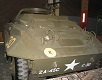
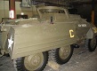
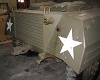
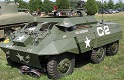
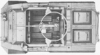
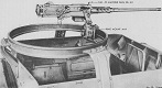
The M20 was standardized as the armored utility car M10 in April 1943, but the designation was changed to M20 to avoid confusion with the 3" GMC M10, alongside which the M20 was to serve in tank destroyer units. The M20 was based on the M8 armored car, and essentially replaced the latter's gun turret with a .50cal MG ring mount. The M20 used the ring mount M49 or M49A1 until August 1944, when production switched to the ring mount M66. . The later M49A1 added a a deflector shield and a skate-type backrest for the gunner, and substituted a different carriage with a connecting stabilizer. The M66 mount used roller-bearing construction, and the inner ring was rotated to traverse the weapon. A back rest was provided to allow the operator to use his whole body to move the gun. November 1944 saw the addition of a second generator in M20s fielding two radios. Improvements to the M8, such as stowage bins and stronger front leaf springs, were also grafted onto the M20 during production.
